1
Description and Operating Instructions MICE
Industrial ETHERNET Modular Industrial Media modules
Communication Equipment
The Modular Industrial Communication
Equipment, MICE, is a modular network
component. It was developed particularly
for use in an industrial environment.
The media modules described in this
instructions are the interface of the device
to the LAN and can be plugged onto the following basic modules of the MICE switch:
– MS2108-2 (MICE 2000)
– MS3124-4 (MICE 3000)
– MS4128-5 (MICE 4000 / Power MICE)
– MS20-… and MS30-…
The MB-2T expansion module allows you to
add 2 slots to the MS20-1600, MS30-1602,
MS3124-4, MS4128-5 MICE switch basic
module for installing media modules.
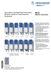
MM2-2FXM3/2TX1
MM2-4TX1
MM4-4TX/SFP
MM2-2FLM4
MM2-2FXP4
MM3-4TX5
MM2-2FXM2
MM2-2FXS2
MICE allows you to construct switched
Industrial ETHERNET networks that conform to the IEEE 802. and 802.3u standard
using copper wires or optical fibers in a bus
or ring topology.
In the
– User manual „Installation“
– User manual „Basic configuration“
– User manual „Redundancy configuration“
– Reference manual „Web-based Interface“
– Reference manual „Command Line
Interface“
you will find a detailled description of the
MICE and further information.
MM3-2AUI MM3-2FXM4/2TX1 MM3-1FXM2/3TX1
MM3-2FXS2/2TX1 MM3-1FXL2/3TX1
MM3-2FXM2/2TX1 MM3-1FXS2/3TX1
MM2-4FXM3
MM3-4FXM2
MM3-4FXS2
MB-2T expansion module
Hirschmann. Simply a good Connection.
MM3-4FXM4
MM3-4FLM4
MM3-4FXP4
The performance features described here
are binding only if they have been expressly
guaranteed in the contract. We have
checked that the contents of the technical
publication agree with the hardware and
software described. However, it is not possible to rule out deviations completely, so we
are unable to guarantee complete agreement. However, the details in the technical
publication are checked regularly. Any corrections which prove necessary are contained in subsequent editions. We are grateful
for suggestions for improvement.
General Safety Instructions
1.3 MB-2T EXPANSION MODULE
M Particular attention is to be paid to all
warnings and items of information relating
to safety.
The MB-2T expansion module allows you to
add 2 slots to the MS20-1600, MS30-1602,
MS3124-4, MS4128-5 MICE switch basic
module for installing media modules.
z
z
Warning!
LED- or LASER components according to IEC 60825-1 (2003):
CLASS 1 LASER PRODUCT.
LIGHT EMITTING DIODE - CLASS 1
LED PRODUCT.
s
Warning!
(POF media modules ...-P4-...
and MM20-P9P9...)
LED light
DO NOT STARE INTO THE BEAM OR
VIEW DIRECTLY WITH OPTICAL
INSTRUMENTS (e.g. lens, microscope). Failure to observe this warning
within a distance of 100 mm can
endanger your eyes. Light is emitted
from the optical connectors or from
the ends of the optical fibers that are
connected to them.
Light Emitting Diode CLASS 2M
Wave length 650 nm
Power <2 mW
According to IEC/CEI 60825-1:2003.
We reserve the right to make technical
modifications.
Permission is not given for the circulation
or reproduction of this document, its use or
the passing on of its contents unless granted expressly. Contravention renders the
perpetrator liable for compensation for
damages. All rights reserved, in particular
in the case of patent grant or registration of
a utility or design.
Copyright
© Hirschmann
Automation and Control GmbH 2008
All Rights Reserved
Safety instructions
Certified usage
Please observe the following:
z
Warning
The device may only be employed
for the purposes described in the
catalog and technical description,
and only in conjunction with external
devices and components recommended or approved by Hirschmann.
The product can only be operated
correctly and safely if it is transported, stored, installed and assembled
properly and correctly. Furthermore,
it must be operated and serviced
carefully.
Supply voltage
To be supplied by a NEC Class 2 power
supply via MICE switch module.
For Power over Ethernet modules: Connect
a NEC Class 2 power supply only.
Use 60/75°C or 75°C copper (CU) wire only.
Warning!
Any work that may have to be performed on the electrical installation
should be performed by fully qualified technicians only.
ESD guidelines
The media modules contain components
highly sensitive to electrostatic fields.These
components can be easily destroyed or
have their lives shortened by an electrical
field or by a discharge caused by touching
the contacts.
You can find more informationen about
devices vulnerable to electrostatic fields in
DIN EN 61340-5-1 (2001-08) and
DIN EN 61340-5-2 (2002-01)
,
Recycling Note:
After its use, this product has to be
processed as electronic scrap and
disposed of according to the prevailing waste disposal regulations of
your community / district / country /
state.
M Beware of possible short circuits when
connecting a cable section with conductive
shielding braiding.
Housing
z
Warning!
Only technicians authorized by
Hirschmann are permitted to open
the housing.
M Make sure that the electrical installation
meets local or nationally applicable safety
regulations.
z
2
Warning!
Never insert pointed objects (thin
screwdrivers, wires, etc.) into the
inside of the subrack! This especially applies to the area behind the
socket connectors. Failure to observe this point may result in injuries caused by electric shocks.
SFP modules are optical transceivers
(Fast ETHERNET and Gigabit ETHERNET
SFP modules see chapter 7 Technical Data).
The SFP modules are plugged into the SFP
slots of the Fast ETHERNET media module
MM3-4SFP (MM20-Z6Z6Z6Z6) or of the
Gigabit ETHERNET media modules
MM4-4TX/SFP / MM4-2TX/SFP to provide a
F/O port.
The MM3-4SFP (MM20-Z6Z6Z6Z6) has four
slots for SFP modules (100 Mbit/s).
The MM4-4TX/SFP / MM4-2TX/SFP has
four/two TP interfaces and four/two slots for
SFP modules (100/1000 Mbit/s). Inserting
the SFP module deactivates the corresponding TP interface.
1.5 MM22-T1T1T1T1
POE MEDIA MODULE
The MM22-T1T1T1T1 PoE media module
(deeper module style) supports Power over
ETHERNET (PoE) in compliance with IEEE
802.3af. It enables the connection and the
remote supply of e.g. IP telephones (voice
over IP), webcams, sensors, print servers
and WLAN access points via 10BASET/100BASE-TX. With PoE, the power supply
of these data terminal equipments is served
via the twisted pair cable.
The MM22-T1T1T1T1 media module offers
four 10BASE-T/100BASE-TX ports (RJ45
connectors) for connecting network segments or PoE data terminal equipments
(PD, Powered Device) up to class 0 (respectively class 3) maximum.
The current is supplied on the idle wire
pairs (spare pairs); the ports are not electrically isolated against each other.
In compliance with IEEE 802.3af, each port
has the attributes:
– Endpoint PSE
– Alternative B.
2. Functional description
Shielding Ground
Note: The shielding ground of the connectable twisted pairs lines is connected to the
front panel as a conductor.
1.4 SFP MODULES
1. MICE Hardware
1.1 SWITCH BASIC MODULES
The documentation enclosed to the switch
basic module gives you a detailed description of the switch basic modules:
– „User Manual Installation
Industrial ETHERNET Switch MICE
MS20/MS30” for MS20-… and MS30-…
– „User Manual Installation
Industrial ETHERNET Switch Power MICE”
– “Description and Operating Instructions
Industrial ETHERNET Modular Industrial
Communication Equipment MICE/Power
MICE” for
– MS2108-2 (MICE 2000)
– MS3124-4 (MICE 3000)
1.2 MEDIA MODULES
– MICE 2000: See Table 1.
– MICE 3000: See Table 2.
– MICE 4000: See Table 3.
– MICE media modules open variant:
See Table 4.
The ports of a MICE represent a terminal
connection for the connected LAN segment.
You can connect single devices or complete
network segments.
2.1 INTERFACES
TP/TX/FL/FX terminal devices or other
TP/TX/FL/FX segments can be connected to
the 10/100/1000 Mbit/s ports of the media
modules.
The MICE and MS20 supports both ETHERNET 10 Mbit/s and Fast ETHERNET 100
Mbit/s, the Power MICE and MS30 supports
additionally Gigabit ETHERNET 1000 Mbit/s.
The TP/TX ports support autocrossing,
autonegotiation and autopolarity.
2.2 DIP SWITCH (MM3-AUI)
With the 3-pin DIP switch on the MM3-2AUI
module
– you can switch on or off the SQE test function at port 1 with the SQE-Test Port 1
switch.
State of delivery: switch in position 0 (Off),
i.e. SQE test function not active.
– you can switch on or off the SQE test function at port 2 with the SQE-Test Port 2
switch.
State of delivery: switch in position 0
(Off), i.e. SQE test function not active.
– you can switch on or off the monitoring
of the DTE voltage, for both ports
together, with the DTEPower-Monitor
switch.
– ON: monitoring of the DTE voltage
active, data transmission only possible
if DTE voltage available.
– OFF: no monitoring of the DTE voltage,
data transmission always possible.
– State of delivery: switch in position 0
(OFF), i.e. no monitoring of DTE
voltage.
3. Assembly, startup procedure
and dismantling
3.1 UNPACKING, CHECKING
M Check whether the package was delivered completely (see scope of delivery).
M Check the individual parts for transport
damage.
z
Warning!
Use only undamaged parts!
3.2 ASSEMBLING MEDIA MODULES
Media modules can be assembled and
disassembled during running operation.
M To fasten a media module, first remove
the protective cap over the plug of the
MICE.
M Plug the media module onto the plug.
M Tighten the 4 screws on the corners of
the media module.
M Check whether the switch pre-setting
suits your requirements.
M Fit the signal lines.
3.3 ASSEMBLING SFP MODULES
M To fasten a SFP module, first remove
the protective cap over the socket.
M Insert the SFP module with the closed
lock into the socket until you hear it
snap in.
Note: Use only Hirschmann SFP modules.
3.4 ASSEMBLING THE MB-2T
EXPANSION MODULE
The MB-2T expansion module can be
installed while in running operation.
M On the right side of the switch basic
module, loosen the screw at the top and
at the bottom (1-3 revolutions).
M Remove the side cover.
M If you have not yet done so, mount the
switch basic module onto the top-hat
rail.
M Slide the MB-2T expansion module on
the top-hat rail toward the switch basic
module until the modules plug into
each other.
M On the switch basic module, tighten the
screws at the top and at the bottom.
All these conditions are met by the
RPS60/48V EEC power supply unit.
M Connect the PoE voltage to the 3-pin
terminal block (included in the scope of
delivery), as shown in the following
figure.
Make sure that your installation complies with the following conditions:
– Length of the supply line < 3 m.
– Cross-section of the supply lines is
dimensioned for 1.5 A
+
48 V -
3.5 STARTUP PROCEDURE
You start up the MICE by connecting the
supply voltage via the terminal block(s) on
the MICE basic module. Lock the terminal
block(s).
Fig. 1: 3-pin terminal block of the
PoE media module
3.6 CONNECTING THE
MM22-T1T1T1T1 POE MEDIA MODULE
The MM22-T1T1T1T1 PoE media module is
supplied with the PoE voltage (48 V DC
safety extra-low voltage) via an external
power supply unit. The PoE voltage is fed
into the 3-pin terminal block of the PoE
media module. The twisted pair cables are
supplied with the PoE voltage on port 1 to 4
via the spare pairs (pins 4&5 and 7&8 of the
RJ45 sockets).
Note: Use 4-pair twisted pair cables for
connecting the data terminal equipments.
Only connect data terminal equipments
which are conform to IEEE 802.3af.
Note: Only use the Hirschmann
RPS60/48V EEC power supply unit for providing the PoE voltage.
M Make sure that the external power
supply unit being used for providing the
PoE voltage meets, among other things,
the following requirements:
– Isolation requirements in compliance
with IEEE 802.3af (electrical strength
of the 48V output to “rest of the
world" 2250 V DC for 1 min.)
– Output power < 100 W.
– Current limiting < 2 A.
– Power supply unit and PoE media
module form a "Limited Power Source" in compliance with IEC60950-1.
– The external PoE power supply unit
has to be able to provide the power
for the PDs being connected.
M Mount the terminal block for the PoE
supply voltage on the bottom side of
the PoE module via snap lock. Push it
until it locks into position.
4. Further support
In the event of technical queries, please talk
to the Hirschmann contract partner responsible for looking after your account or
directly to the Hirschmann office. You can
find the addresses of our contract partners
– on the Internet
(http://www.hirschmann-ac.de)
Our support line is also at your disposal:
Tel. +49(1805) 14-1538
Fax +49(7127) 14-1551
Answers to Frequently Asked Questions can
be found on the Hirschmann product internet sites on
www.hirschmann-ac.de
The FAQs are located under „Service“ in
the Automation and Control section.
www.hicomcenter.com
gives you an up-to-date overview of
training courses about technology and
products.
5. Technical data
Dimensions W x H x D
38 mm x 110 mm x 79 mm (MM2-...)
38 mm x 110 mm x 119 mm (MM3-..., MM4-...)
38 mm x 110 mm x 79 bzw. 119 mm (MM20-..., MM21-..., MM22-..., MM23-..., MM30-..., MM33-...)
Humidity
Atmospheric pressure
Pollution degree
Laser protection
10% to 95% (non condensing)
up to 2000 m (795 hPa, higher altitudes on demand)
2
Class 1 conforming to EN 60825
Class 2M conforming to EN 60825-1:2003-10 (POF media modules ...-P4-... and
MM20-P9P9...)
Protection type
EMV interference proof
EN 61000-4-2, Discharge of static electricity
IP 20
EN 61000-4-3, Electromagnetic fields
EN 61000-4-4, Fast transients (burst),
Test level 3, x
Contact discharge: test level 3
Air discharge: test level 3
Test level 3 (80 - 2000 MHz)
- Power line
- Data line
A 1)
4 kV
8 kV
10 V/m
2 kV
1 kV
B 1)
8 kV
15 kV
20 V/m
4 kV
4 kV
H 1)
8 KV
15 kV
20 V/m
4 kV
4 kV
3
EN 61000-4-5 Surge voltage
EN 61000-4-6 Cable-based RF faults,
Test level 3
EN 61000-4-9 Impulse shaped magnetic fields
EMV emitted immunity
EN 55022
FCC 47 CFR Part 15
German Lloyd
Stability
Vibration
IEC 60068-2-6
German Lloyd
- Power line, line/line: test level 2
- Power line, line/earth: test level 3
- Data line: test level 3
10 kHz - 150 kHz
150 kHz - 80 MHz
Test level 4
1 kV
2 kV
4 kV
3V
10 V
300 A/m
1 kV
2 kV
4 kV
3V
10 V
300 A/m
A 1)
Class A
Yes
Class A
Yes
Rules for Classifikation and Construction VI-7-3 Part 1 Ed. 2001
B 1)
Yes
Yes
Yes
H 1)
Yes
Yes
Yes
Test FC, test level in line with IEC 61131-2V
Guidelines for the Performance
of Type Tests Part 1
Normal Installation in line with EN 61850-3
Test Ea, test level in line with IEC 61131-2
Normal Installation in line with EN 61850-3
Yes
-
Yes
Yes
Yes
Yes
Yes
-
Yes
Yes
Yes
Yes
Yes
Yes
IEC 870-2-2 Table 3
IEC 60068-2-27
IEC 870-2-2 Table 3
1) Product code A: Certification = CE, UL
Product code B: Certification = CE, UL, GL, Railway (along track), Substation, ATEX
Product code H: Certification = CE, UL, GL, Railway (along track), Substation
The media modules in Table 1 to 3 (see page 5) have the certification “A”.
Shock
0,5 kV
1 kV
1 kV
3V
10 V
-
Network size
AUI port
Length of a AUI cable
TP/TX port 10/100/1000BASE-T/TX
Length of a twisted pair segment
F/O port 10BASE-FL
Product code Wave length
-M4
MM
850 nm
-M4
MM
850 nm
F/O port 100BASE-FX
Product code
-M2, -M4
MM
-M2, -M4
MM
-S2
SM
-L2
LH
-P4
MM POF
-P4
MM HCS
-P9
MM POF
-G2
LH+
F/O port 100BASE-FX
Product code
M-FAST-SFP-...
-MM/LC (EEC) MM
-MM/LC (EEC) MM
-SM/LC (EEC) SM
-SM+/LC (EEC) SM
-LH/LC
SM
50 m max.
100 m (328 ft) max. (cat5e cable with 1000BASE-T)
System attenuation
0-9.5 dB
0-12.5 dB
Expansion
0-2,000 m
0-3,000 m
Fiber data
3.0 dB/km; 400 MHz*km
3.2 dB/km; 200 MHz*km
Wave length
Fiber
System attenuation
1300 nm
50/125 µm
0-8 dB
1300 nm
62.5/125 µm
0-11 dB
1300 nm
9/125 µm
0-16 dB
1550 nm
9/125 µm
7-29 dB
650 nm
980/1000 µm
0-15.5 dB
650 nm
200/230 µm
0-7.0 dB
650 nm
980/1000 µm
0-14.0 dB
1550 nm
9/125 µm
14-47 dB
(SFP Fiberoptic Fast ETHERNET Transceiver)
Wave length
Fiber
System attenuation
Expansion
0-5 km
0-4 km
0-30 km
24-86 km
0-65 m
0-140 m
0-55 m
67-176 km
Fiber data
1.0 dB/km; 800 MHz*km
1.0 dB/km; 500 MHz*km
0.4 dB/km; 3.5 ps/(nm*km)
0.3 dB/km; 19 ps/(nm*km)
200 dB/km; 10 MHz*km
10 dB/km; 17 MHz*km
200 dB/km; 10 MHz*km
0.25 dB/km; 19 ps/(nm*km)
Expansion
Fiber data
0-5 km
0-4 km
0-25 km
25-65 km
40-104 km
1.0 dB/km; 800 MHz*km
1.0 dB/km; 500 MHz*km
0.4 dB/km; 3.5 ps/(nm*km)
0.4 dB/km; 3.5 ps/(nm*km)
0.25 dB/km; 19 ps/(nm*km)
Expansion
Fiber data
0-550 m
0-550 m
0-275 m
0-550 m
0-20 km
24-72 km
60-120 km
3.0 dB/km; 400 MHz*km
1.0 dB/km; 800 MHz*km
3.2 dB/km; 200 MHz*km
1.0 dB/km; 500 MHz*km
0.4 dB/km; 3.5 ps/(nm*km)
0.25 dB/km; 19 ps/(nm*km)
0.25 dB/km; 19 ps/(nm*km)
1310 nm
1310 nm
1310 nm
1310 nm
1550 nm
Fiber
50/125 µm
62.5/125 µm
50/125 µm
62.5/125 µm
9/125 µm
9/125 µm
9/125 µm
0-11 dB
0-8 dB
0-13 dB
10-29 dB
10-29 dB
F/O port 1000BASE-FX (SFP Fiberoptic Gigabit ETHERNET Transceiver)
Product code Wave length
Fiber
System attenuation
M-SFP-...
-SX/LC (EEC) MM
850 nm
50/125 µm
0-7.5 dB
-LX/LC (EEC) SM
1310 nm 1)
50/125 µm
0-11 dB
-SX/LC (EEC) MM
850 nm
62.5/125 µm
0-7.5 dB
62.5/125 µm
0-11 dB
-LX/LC (EEC) SM
1310 nm 1)
-LX/LC (EEC) SM
1310 nm
9/125 µm
0-11 dB
-LH/LC (EEC) LH
1550 nm
9/125 µm
6-22 dB
-LH+/LC
LH
1550 nm
9/125 µm
15-32 dB
MM = multimode, SM = singlemode, LH = singlemode longhaul
with F/O adapter in line with IEEE802.3-2002 clause 38 (single-mode fiber offset-launch mode conditioning patch cord)
1)
Displays
Device status
Port status
1 x green LED
P – Power, internal supply voltage present
4 x green/yellow LED 1 to 4 – The meaning depends on the setting of the display status.
Controls (MM3-2AUI)
3-pole DIP switch
4
1 – SQE-Test Port 1 – ON = SQE test function on port 1 enabled
2 – SQE-Test Port 2 – ON = SQE test function on port 2 enabled
3 – DTEPower-Monitor – ON = Monitoring of the DTE voltage active
Scope of delivery
MICE media module incl.
Labels, description and operating instructions
Accessories
Pocket Guide
AutoConfigurationAdapter ACA 11
Terminal access cable
6-pin terminal block (50 pieces)
Rail Power Supply RPS 30
Rail Power Supply RPS 80 EEC
Rail Power Supply RPS 120 EEC
Rail Power Supply RPS60/48V EEC
Network Management Software HiVision
Network Management Software Industrial HiVision
280 720-851
943 751-001
943 301-001
943 845-002
943 662-003
943 662-080
943 662-120
943 952-001
943 471-100
943 156-xxx
6. MICE media modules
6.1 PORT ASSIGNMENT (EXAMPLES)
MM4-4TX/SFP
1
1
2
3
2
1
4
3
2
1* 2*
3
4
4
3* 4*
MM3-4SFP (MM20-Z6Z6Z6Z6)
1
2
3
MM20-Z6Z6Z6Z6
MM3-4FLM4
Port 1 to 4 (SFP ports) alternatively to port 1* to 4* (TP ports)
MM2-4FXM3
4
6.2 NUMBER AND KIND OF MEDIA CONNECTORS
MICE 2000 media modules
Module type
AUI port
MM2-4TX1(-EEC)
MM2-2FLM4
MM2-2FXP4
MM2-4FXM3
MM2-2FXM3/2TX1
MM2-2FXM2
MM2-2FXS2
–
–
–
–
–
–
–
TP ports
10/100
F/O port
multimode
10 Mbit/s
4, RJ45
–
–
–
2, RJ45
–
–
–
2, ST
–
–
–
–
–
F/O port
multimode
POF
100 Mbit/s
–
–
2, ST
–
–
–
–
F/O port
multimode
100 Mbit/s
–
–
–
4, MTRJ
2, MTRJ
2, DSC
–
F/O port
singlemode
1300 nm,
100 Mbit/s
–
–
–
–
–
–
2, DSC
F/O port
singlemode
1550 nm,
100 Mbit/s
–
–
–
–
–
–
–
Supported since
MICE SW release
PowerMS20
MICE MICE MS30
1.0
1.0 1.0
1.0
1.0 1.0
4.0
1.0 1.0
1.0
1.0 1.0
1.0
1.0 1.0
1.0
1.0 1.0
2.0
1.0 1.0
Table 1: Number of media connectors each MICE 2000 media module, kind of connector and necessary software
MICE 3000 media modules
Module type
AUI port
MM3-2AUI
MM3-4TX5
MM3-4TX1-RT 1)
MM3-2FLM4/2TX1-RT 1)
MM3-4FLM4
MM3-4FXP4
MM3-1FXM2/3TX1
MM3-2FXM2/2TX1(-EEC)
MM3-2FXM2/2TX1-RT 1)
MM3-2FXM4/2TX1
MM3-4FXM2
MM3-4FXM4
MM3-1FXS2/3TX1(-EEC)
MM3-2FXS2/2TX1
MM3-2FXS2/2TX1-RT 1)
MM3-4FXS2
MM3-1FXL2/3TX1
2, Sub-D-St.
–
–
–
–
–
–
–
–
–
–
–
–
–
–
–
–
TP ports
10/100
F/O port
multimode
10 Mbit/s
–
4, M12
4, RJ45
2, RJ45
–
–
3, RJ45
2, RJ45
2, RJ45
2, RJ45
–
–
3, RJ45
2, RJ45
2, RJ45
–
3, RJ45
–
–
–
2, ST
4, ST
–
–
–
–
–
–
–
–
–
–
–
–
F/O port
multimode
POF
100 Mbit/s
–
–
–
–
–
4, ST
–
–
–
–
–
–
–
–
–
–
–
F/O port
multimode
100 Mbit/s
–
–
–
–
–
–
1, DSC
2, DSC
2, DSC
2, ST
4, DSC
4, ST
–
–
–
–
–
F/O port
singlemode
1300 nm,
100 Mbit/s
–
–
–
–
–
–
–
–
–
–
–
–
1, DSC
2, DSC
2, DSC
4, DSC
–
F/O port
singlemode
1550 nm,
100 Mbit/s
–
–
–
–
–
–
–
–
–
–
–
–
–
–
–
–
1, DSC
Supported since
MICE SW release
PowerMS20
MICE MICE MS30
4.0
1.0 1.0
4.0
1.0 1.0
5.0
2.0 1.0
5.0
2.0 1.0
2.0
1.0 1.0
4.0
1.0 1.0
3.1
1.0 1.0
2.0
1.0 1.0
5.0
2.0 1.0
3.1
1.0 1.0
2.0
1.0 1.0
3.1
1.0 1.0
3.1
1.0 1.0
2.0
1.0 1.0
5.0
2.0 1.0
3.1
1.0 1.0
2.0
1.0 1.0
Table 2: Number of media connectors each MICE 3000 media module, kind of connector and necessary software
1) Realtime modules, in line with IEEE 1588 PTP (Precision Time Protocol)
5
MICE 4000 media modules
Module type
TP ports
10/100/1000
MM4-2TX/SFP
MM4-4TX/SFP
SFP ports
alternativ zu TP-Ports/
alternatively to TP ports
2, RJ45
4, RJ45
Supported since
MICE SW release
Power MS20
MICE MICE MS30
–
2.0
1.0
–
1.0
1.0
2
4
Table 3: Number of media connectors each MICE 4000 media module, kind of connector and necessary software
Open variant media modules
Module type
TP ports
10/100/1000
SFP ports
alternativ zu TP-Ports/
alternatively to TP ports
Supported since
MICE SW release
Power MS20
MICE MICE MS30
MM20..., MM21..., MM30... 0 to 4 ports (media and connector at your option, see chapter 8 “Open Variant”)
–
–
2.0
MM22-T1T1T1T1
4 ports (twisted pair, RJ45 connector)
–
3.0
3.0
MM20-Z6Z6Z6Z6
4 ports (fiber optic, SFP slot, 100 Mbit/s)
–
4.0
4.0
MM20-P9P9P9P9
4 ports (fiber optic, SCRJ connector, 100 Mbit/s)
–
4.2
4.2
MM20-P9P9T1T1
4 ports (2 x fiber optic, SCRJ connector, 100 Mbit/s; 2 x twisted pair, RJ45 connector)
–
4.2
4.2
MM23-T1T1T1T1...SAHH1) 4 ports (twisted pair, RJ45 connector)
–
5.0
5.0
MM23-M2M2T1T1...SAHH1)4 ports (2 x multimode FX, duplex SC connector, 100 Mbit/s; 2 x twisted pair, RJ45 connector) –
5.0
5.0
5.0
5.0
MM23-S2S2T1T1...SAHH1) 4 ports (2 x singlemode FX, duplex SC connector, 100 Mbit/s; 2 x twisted pair, RJ45 connector) –
–
5.0
5.0
MM23-F4F4T1T1...SAHH1) 4 ports (2 x multimode FL, ST connector, 10 Mbit/s; 2 x twisted pair, RJ45 connector)
MM33-O7O79999...SAHH1) 2 ports (2 x combo ports twisted pair RJ45 or alternatively SFP slot, 1000 Mbit/s)
–
5.0
5.0
Table 4: MICE open variant media module, necessary software
1) Realtime modules, in line with IEEE 1588 PTP (Precision Time Protocol)
6.3 PIN ASSIGNMENT OF THE INTERFACES
10/100 Mbit/s twisted pair connection
n.c.
n.c.
TDn.c.
n.c.
TD+
RDRD+
Pin 8
Pin 7
Pin 6
Pin 5
Pin 4
Pin 3
Pin 2
Pin 1
Fig. 3: Pin assignment of a TP/TX interface
in MDI-X mode, RJ45 socket
TD+
1
2
RD+
RD-
4
3
TD-
10/100 Mbit/s twisted pair connection
PoE (Power over Ethernet) at
MM22-T1T1T1T1 PoE media module
VVTDV+
V+
TD+
RDRD+
Pin 8
Pin 7
Pin 6
Pin 5
Pin 4
Pin 3
Pin 2
Pin 1
Fig. 5: Pin assignment of a TP/TX interface
with PoE, for supply via the the idle wire
pairs (spare pairs), RJ45 socket
10/100/1000 Mbit/s twisted pair
connection
BI_DCBI_DC+
BI_DABI_DDBI_DD+
BI_DA+
BI_DBBI_DB+
Pin 8
Pin 7
Pin 6
Pin 5
Pin 4
Pin 3
Pin 2
Pin 1
Fig. 7: Pin assignment of the 1000 Mbit/s
twisted pair interface
AUI connection
3-pin terminal block (PoE module)
Fig. 4: Pin assignment of a TP/TX interface,
M12 socket
+
shielding CO
n.c.
GND
output DI-A
shielding DI
input DO-A
output CI-A
shielding CI
48 V -
Pin 8
Pin 7
Pin 6
Pin 5
Pin 4
Pin 3
Pin 2
Pin 1
Pin 15
Pin 14
Pin 13
Pin 12
Pin 11
Pin 10
Pin 9
n.c.
shielding 12 V
voltage 12 V
output DI-B
shielding DO
input DO-B
output CI-B
Fig. 6: 3-pin terminal block of the
PoE media module
Fig. 8: Pin assignment of the AUI interface
Power
output
Storage
temperature
Order
number
7. General data
Power
consumption
Operating temp.
surrounding air
MICE 2000 media modules:
MM2-4TX1
MM2-4TX1-EEC
MM2-2FXP4
MM2-4FXM3
MM2-2FXM3 / 2TX1
MM2-2FXM2
MM2-2FXS2
0.8 W
0.8 W
3.8 W
6.8 W
3.8 W
3.8 W
3.8 W
2.8 Btu (IT)/h
2.8 Btu (IT)/h
13.0 Btu (IT)/h
23.2 Btu (IT)/h
13.0 Btu (IT)/h
13.0 Btu (IT)/h
13.0 Btu (IT)/h
0 °C … +60 °C
-40 °C … +70 °C
0 °C … +60 °C
0 °C … +60 °C
0 °C … +60 °C
0 °C … +60 °C
0 °C … +60 °C
-40 °C … +70 °C
-40 °C … +85 °C
-40 °C … +70 °C
-40 °C … +70 °C
-40 °C … +70 °C
-40 °C … +70 °C
-40 °C … +70 °C
943 722-101
943 722-151
943 842-101
943 721-101
943 720-101
943 718-101
943 719-101
MICE 3000 media modules:
MM3-2AUI
MM3-4FLM4
MM3-2FLM4 / 2TX1-RT
3.4 W
5.0 W
5.0 W
11.6 Btu (IT)/h
17.1 Btu (IT)/h
17.1 Btu (IT)/h
0 °C … +60 °C
0 °C … +60 °C
0 °C … +60 °C
-40 °C … +70 °C
-40 °C … +70 °C
-40 °C … +70 °C
943 840-101
943 760-101
943 117-004
6
MM3-4TX5
MM3-4TX1-RT
MM3-4FXP4
MM3-1FXM2 / 3TX1
MM3-1FXM2 / 3TX1-EEC
MM3-2FXM2 / 2TX1
MM3-2FXM2 / 2TX1-EEC
MM3-2FXM2 / 2TX1-RT
MM3-2FXM4 / 2TX1
MM3-4FXM2
MM3-4FXM4
MM3-1FXS2 / 3TX1
MM3-1FXS2 / 3TX1 EEC
MM3-2FXS2 / 2TX1
MM3-2FXS2 / 2TX1-EEC
MM3-2FXS2 / 2TX1-RT
MM3-4FXS2
MM3-1FXL2 / 3TX1
MM3-4SFP
0.8 W
0.8 W
6.8 W
2.3 W
2.3 W
3.8 W
3.8 W
3.8 W
3.8 W
6.8 W
6.8 W
2.3 W
2.3 W
3.8 W
3.8 W
3.8 W
6.8 W
3.4 W
8.0 W
2.8 Btu (IT)/h
2.8 Btu (IT)/h
23.2 Btu (IT)/h
7.9 Btu (IT)/h
7.9 Btu (IT)/h
13.0 Btu (IT)/h
13.0 Btu (IT)/h
13.0 Btu (IT)/h
13.0 Btu (IT)/h
23.2 Btu (IT)/h
23.2 Btu (IT)/h
7.9 Btu (IT)/h
7.9 Btu (IT)/h
13.0 Btu (IT)/h
13.0 Btu (IT)/h
13.0 Btu (IT)/h
23.2 Btu (IT)/h
11.6 Btu (IT)/h
27.3 Btu (IT)/h
0 °C … +60 °C
0 °C … +60 °C
0 °C … +60 °C
0 °C … +60 °C
-40 °C … +70 °C
0 °C … +60 °C
-40 °C … +70 °C
0 °C … +60 °C
0 °C … +60 °C
0 °C … +60 °C
0 °C … +60 °C
0 °C … +60 °C
-40 °C … +70 °C
0 °C … +60 °C
-40 °C … +70 °C
0 °C … +60 °C
0 °C … +60 °C
0 °C … +60 °C
0 °C … +60 °C
-40 °C … +70 °C
-40 °C … +70 °C
-40 °C … +70 °C
-40 °C … +70 °C
-40 °C … +85 °C
-40 °C … +70 °C
-40 °C … +85 °C
-40 °C … +70 °C
-40 °C … +70 °C
-40 °C … +70 °C
-40 °C … +70 °C
-40 °C … +70 °C
-40 °C … +85 °C
-40 °C … +70 °C
-40 °C … +85 °C
-40 °C … +70 °C
-40 °C … +70 °C
-40 °C … +70 °C
-40 °C … +70 °C
943 841-101
943 117-001
943 843-101
943 839-101
943 839-151
943 761-101
943 761-151
943 117-002
943 837-101
943 764-101
943 835-101
943 838-101
943 838-151
943 762-101
943 762-151
943 117-003
943 836-101
943 763-101
943 938-001
MICE 4000 media modules:
MM4-4TX / SFP
MM4-2TX / SFP
9.0 W
5.8 W
30.8 Btu (IT)/h
19.8 Btu (IT)/h
0 °C … +60 °C
0 °C … +60 °C
-40 °C … +70 °C
-40 °C … +70 °C
943 010-001
943 622-001
Open variant media modules (You will find further informationen on www.hirschmann-ac.com):
MM20-... 4 TX-/0 FX-Ports
0.8 W
2.8 Btu (IT)/h
see chapter 8
see chapter 8
MM20-... 3 TX-/1 FX-Ports
2.3 W
7.9 Btu (IT)/h
see chapter 8
see chapter 8
MM20-... 2 TX-/2 FX-Ports
3.8 W
13.0 Btu (IT)/h
see chapter 8
see chapter 8
MM20-... 0 TX-/2 FX-Ports
3.8 W
13.0 Btu (IT)/h
see chapter 8
see chapter 8
MM20-... 1 TX-/3 FX-Ports
5.3 W
18.1 Btu (IT)/h
see chapter 8
see chapter 8
MM20-... 0 TX-/4 FX-Ports
6.8 W
23.2 Btu (IT)/h
see chapter 8
see chapter 8
MM20-A8A89999
3.4 W
11.6 Btu (IT)/h
see chapter 8
see chapter 8
MM20-F4F4F4F4
5.0 W
17.1 Btu (IT)/h
see chapter 8
see chapter 8
MM20-Z6Z6Z6Z6
8.0 W
27.3 Btu (IT)/h
see chapter 8
see chapter 8
MM20-P9P9P9P9SAHH
8.0 W
27.3 Btu (IT)/h
0 °C ... +60 °C
-40 °C ... +70 °C
MM20-P9P9T1T1SAHH
5.2 W
17.8 Btu (IT)/h
0 °C ... +60 °C
-40 °C ... +70 °C
MM30-O7O7O7O7
9.0 W
30.8 Btu (IT)/h
see chapter 8
see chapter 8
MM30-O7O79999
5.8 W
19.8 Btu (IT)/h
see chapter 8
see chapter 8
MM21-T1T1T1T1
0.8 W
2.8 Btu (IT)/h
see chapter 8
see chapter 8
MM21-F4F4T1T1
5.0 W
17.1 Btu (IT)/h
see chapter 8
see chapter 8
MM21-M2M2T1T1
3.8 W
13.0 Btu (IT)/h
see chapter 8
see chapter 8
MM21-S2S2T1T1
3.8 W
13.0 Btu (IT)/h
see chapter 8
see chapter 8
MM22-T1T1T1T1
0.8 W
2.8 Btu (IT)/h
see chapter 8
see chapter 8
MM23-T1T1T1T1...SAHH
4.5 W
15.4 Btu (IT)/h
0 °C ... +60 °C
-40 °C ... +70 °C
MM23-M2M2T1T1...SAHH
6.0 W
20.5 Btu (IT)/h
0 °C ... +60 °C
-40 °C ... +70 °C
MM23-S2S2T1T1...SAHH
5.5 W
18.8 Btu (IT)/h
0 °C ... +60 °C
-40 °C ... +70 °C
MM23-F4F4T1T1...SAHH
5.5 W
18.8 Btu (IT)/h
0 °C ... +60 °C
-40 °C ... +70 °C
MM33-O7O79999...SAHH
7.5 W
25.6 Btu (IT)/h
0 °C ... +60 °C
-40 °C ... +70 °C
product code; chap. 8
product code; chap. 8
product code; chap. 8
product code; chap. 8
product code; chap. 8
product code; chap. 8
product code; chap. 8
product code; chap. 8
product code; chap. 8
product code; chap. 8
product code; chap. 8
product code; chap. 8
product code; chap. 8
product code; chap. 8
product code; chap. 8
product code; chap. 8
product code; chap. 8
product code; chap. 8
product code; chap. 8
product code; chap. 8
product code; chap. 8
product code; chap. 8
product code; chap. 8
Expansion moduel
MB-2T
0W
0 Btu (IT)/h
0 °C … +60 °C
-40 °C … +70 °C
943 733-002
Fast ETHERNET SFP modules:
M-FAST SFP-MM / LC
M-FAST SFP-MM / LC EEC
M-FAST SFP-SM / LC
M-FAST SFP-SM / LC EEC
M-FAST SFP-SM+ / LC
M-FAST SFP-SM+ / LC EEC
M-FAST SFP-LH / LC
0W
0W
0W
0W
0W
0W
0W
0 Btu (IT)/h
0 Btu (IT)/h
0 Btu (IT)/h
0 Btu (IT)/h
0 Btu (IT)/h
0 Btu (IT)/h
0 Btu (IT)/h
0 °C … +60 °C
-40 °C … +70 °C
0 °C … +60 °C
-40 °C … +70 °C
0 °C … +60 °C
-40 °C … +70 °C
0 °C … +60 °C
-40 °C … +70 °C
-40 °C … +85 °C
-40 °C … +70 °C
-40 °C … +85 °C
-40 °C … +70 °C
-40 °C … +85 °C
-40 °C … +70 °C
943 865-001
943 945-001
943 866-001
943 946-001
943 867-001
943 947-001
943 868-001
Gigabit ETHERNET SFP modules:
M-SFP-SX / LC
0W
M-SFP-SX / LC EEC
0W
M-SFP-LX / LC
0W
M-SFP-LX / LC EEC
0W
M-SFP-LH / LC
0W
M-SFP-LH / LC EEC
0W
M-SFP-LH+ / LC
0W
0 Btu (IT)/h
0 Btu (IT)/h
0 Btu (IT)/h
0 Btu (IT)/h
0 Btu (IT)/h
0 Btu (IT)/h
0 Btu (IT)/h
0 °C … +60 °C
-40 °C … +70 °C
0 °C … +60 °C
-40 °C … +70 °C
0 °C … +60 °C
-40 °C … +70 °C
0 °C … +60 °C
-40 °C … +70 °C
-40 °C … +85 °C
-40 °C … +70 °C
-40 °C … +85 °C
-40 °C … +70 °C
-40 °C … +85 °C
-40 °C … +70 °C
943 014-001
943 896-001
943 015-001
943 897-001
943 042-001
943 898-001
943 049-001
7
8. Open variant product code
Alternatively to the order number (ref. table
in chapter 7, last column) you can use the
product code. It offers you, tailored to your
requirements, an additional variety of
media module types.
The product code of your media module is
made from combining the desired product
characteristics in accordance with the following table. The short designation is in
column “Ident.”.
Example:
Product code MM30-O7O7O7O7SA =
media module 1000 Mbit/s with four combo
ports gigabit Ethernet (four SFP ports or
alternatively four TP ports RJ45). This
example equals the module MM4-4TX/SFP
with the order number 943 010-001.
Position
1 to 4
Attribute
Product
Ident.
MM20
MM21
MM22
MM23
MM30
MM33
Feature
Media module 10/100 Mbit/s (standard)
Media module 10/100 Mbit/s (realtime)
Media module 10/100 Mbit/s (Power over Ethernet)
Media module 10/100 Mbit/s (realtime)
Media module 1000 Mbit/s (standard)
Media module 1000 Mbit/s (realtime)
5
- (hyphen)
6 and 7
1st port (media/connector)
T1
T5
M2
M3
M4
S2
S4
L2
G2
F4
P4
P9
O7
A8
Z6
Twisted pair (TX) / RJ45
Twisted pair (TX) / M12
Multimode FX DSC (100 Mbit/s)
Multimode FX MTRJ (100 Mbit/s)
Multimode FX ST (100 Mbit/s)
Singlemode FX DSC (100 Mbit/s)
Singlemode FX ST (100 Mbit/s)
Singlemode longhaul FX DSC (100 Mbit/s)
Singlemode longhaul FX DSC 200km (100 Mbit/s)
Multimode FL ST (10 Mbit/s)
POF FX ST (100 Mbit/s)
POF FX SCRJ (100Mbit/s)
Combo port gigabit Ethernet (SFP 1000 Mbit/s)
AUI Sub-D
Fiber optic / SFP slot (100 Mbit/s)
8 and 9
2nd port (media/connector)
...
See position 6 and 7
10 and 11 3rd port (media/connector)
...
99
See position 6 and 7
Empty
12 and 13 4th port (media/connector)
...
99
See position 6 and 7
Empty
14
Temperature range
S
T
E
Standard 0 °C to +60 °C
Extended -40 °C to +70 °C
Extended -40 °C to +70 °C & Conformal Coating
15
Specifications
A
H
B
CE, UL 508, ISA 12.12.01 (UL 1604)
A plus GL, IEC 61850, IEEE 1613 substation, EN 50121-4 railway (along track)
H plus ATEX100a
Hirschmann Automation and Control GmbH
Stuttgarter Straße 45-51
D-72654 Neckartenzlingen
Germany
Tel.: +49-1805-14-1538
Fax: +49-7127-14-1551
E-Mail: [email protected]
Internet: http://www.hirschmann.com
Printed in Germany
Subject to alterations