1
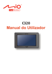
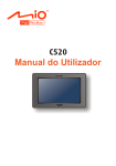
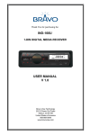
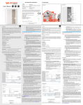
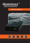
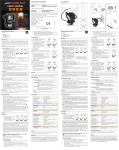
m_Quintezz7000_Cover_new.pmd
1
03.05.2007, 17:33
Illustration I
11
12
10
Illustration II
Illustration III
CLICK
Untitled-11
1
22.12.2005, 18:10
TABLE OF CONTENTS
INTRODUCTION ................................................................................................. 2
XT-7000 FEATURES .......................................................................................... 2
INSTALLATION ................................................................................................. 2
A. GENERAL GUIDELINES ........................................................................................ 2
B. MOUNTING TYPES ................................................................................................ 3
C. POWER CONNECTION .......................................................................................... 3
HOW THE RADAR AND LASER WORK-GENERAL ....................................... 4
A. HOW THE RADAR WORKS .................................................................................. 4
B. RADAR & LASER FREQUENCIES ......................................................................... 4
C. LASER DETECTION .............................................................................................. 4
D. LASER RANGE ...................................................................................................... 4
OPERATION ...................................................................................................... 4
A. SELF TEST ............................................................................................................ 4
B. RADAR & LASER ALARMING ............................................................................... 5
C. HIGHWAY MODE ................................................................................................... 5
D. CITY MODE ............................................................................................................ 5
E. DIP MODE .............................................................................................................. 5
F. MUTE MODE .......................................................................................................... 5
G. HOW THE DETECTOR WARNS ............................................................................ 5
H. WIDE BAND OPTIONS .......................................................................................... 6
I. RESET .................................................................................................................... 6
MAINTENANCE ................................................................................................. 6
FUSE REPLACEMENT INSTRUCTIONS ........................................................ 7
m_Quintezz7000_GB_n.pmd
1
22.12.2005, 14:59
INTRODUCTION
Congratulations !
You have just purchased one of the world’s most
sophisticated radar detectors.
Please read this instruction manual before installation.
All instructions are necessary to achieve optimum use
and trouble-free performance from your XT-7000.
However, owning a radar-detector does not give you a
license to speed. It is to be used as defence against
unnecessary speeding offences caused by revenuegenerating speed traps or occasional lapses of
concentration on the part of the driver. Please drive safely.
XT-7000 FEATURES
1. ON/OFF and Dip key (PWR)
Key to switch the appliance ON/OFF. To dip or to
switch the display off, you should keep this key
pressed.
2. Volume key (/)
Key to adjust the volume of the alarm tones.
3. Mute button
Activates mute mode, which silences the audio
alarm only.
4. City/Highway button (CITY)
Decreases the unit sensitivity to radar signals when
city mode is engaged.
5. Speaker
6. Power Input Jack
7. Receiving window Radar & Laser
8. Receiving window Laser
9. Lock switch for windshield bracket (LOCK)
10. Windshield bracket
11. Power cord
12. Hook and loop fastener tape
INSTALLATION
A. GENERAL GUIDELINES
The following are some guidelines for mounting the
detector :
• Mount the detector so that the receiving window/
sensor has an unobstructed view of the road
ahead. The sensor is located at the opposite end
from the control window.
• The unit may be positioned within 25° of horizontal without significantly degrading performance.
• Do not mount directly behind windshield wipers.
• Do not mount behind a mirrored sunscreen, as it
has a thin layer of aluminium on a plastic film which
will block radar/laser signals.
GB-2
m_Quintezz7000_GB_n.pmd
2
22.12.2005, 14:59
• Mount the unit so that the control panel is plainly
visible for the driver.
• Do not leave it in direct sunlight for long periods of
time.
B. MOUNTING TYPES
We have provided 2 types of mounting methods.
• DASHBOARD MOUNTING (Illustration II)
The hook and loop fastener Velcro tape provided, may
be used to mount your detector on a flat dashboard.
The dashboard must be clean and dry for the fastener
to adhere properly.
• Remove backing from the “LOOP(fuzzy)” piece and
press firmly to the bottom of your unit.
• Clean dashboard with common rubbing alcohol to
remove dirt and grease.
• Peel the backing from the hook side and press the
unit into the desired position on the dashboard.
• WINDSHIELD MOUNTING (Illustration III)
• Insert the supplied suction cups and cushion into
each slot and windshield bracket.
• Slide the windshield bracket into the groove of the
detector.
• Use the Lock switch (LOCK) to lock the windshield
bracket.
• Locate the bracket on a clean windshield and press
firmly on each suction cup.
FOR BEST PERFORMANCE WINDSHIELD
MOUNTING IS RECOMMENDED!
C. POWER CONNECTION
The XT-7000 is designed to operate from the normal 12Volt
electrical system and must be used with a negative ground
electrical system. Do not operate your XT-7000 on positive
ground electrical system. Consult your vehicle owners’
manual if you are not certain of its polarity.
• After you position and mount the detector, insert the
DC power cable into the jack on the detector’s side.
• Remove the vehicle cigar lighter from its socket and
insert the other end of the power cable into the lighter
socket plug.
• For permanent installation, you will have to remove
the cigar lighter plug, take a 1A-fuse and connect the
cables directly.
GB-3
m_Quintezz7000_GB_n.pmd
3
22.12.2005, 14:59
Ka-Band 35.5
Ka-Band 35.7
HOW THE RADAR AND LASER
WORK-GENERAL
A. HOW THE RADAR WORKS
C. LASER DETECTION
The actual process involved in determining a vehicle’s
speed is basically a simple one. It involves directing a
beam of microwave energy at an approaching target vehicle.
A portion of this beam is reflected by the target and is
received by the radar unit that originally transmitted the
signal. The reflected signal is shifted in frequency by an
amount proportional to the speed of the target vehicle. This
phenomenon is known as the Doppler effect. The radar
unit determines the target vehicle speed from the difference
in frequency between the reflected signal and original signal.
Laserdetection is the 13th band that can be detected.
Laser Speed Gun uses pulses of infrared laser light to
measure speed of target by timing each pulses over
time as it is reflected back to the gun.
D. LASER RANGE
The effective range of clocking distance by a laser
gun is less than 1Km. So, mount your laser detector
as low as possible in the car.
The QUINTEZZ XT-7000 offers the possibility to
detect a laser from before as well as from behind.
B. RADAR & LASER FREQUENCIES
The QUINTEZZ XT-7000 can detect 12 radar bands:
X- Band 10.50
GHz
X- Band 10.525
GHz
X- Band 10.6
GHz
K-Band 24.1
GHz
K-Band 24.125
GHz
K-Band 24.150
GHz
K-Band 24.250
GHz
Ka-Band 34.40-36.00 GHz Superior Band
Ka-Band 34.3
GHz
Ka-Band 34.36
GHz
GHz
GHz
OPERATION
A. SELF TEST
Press the ON/OFF key (PWR) to switch the unit ON.
If the unit is switched ON, it will immediately perform
a self-test. During the test the different steps will be
shown in the display and the different tones will be
activated. If the test is finished and the different
settings were shown, the P (Power) will light.
Press the ON/OFF key (PWR) again to switch the
unit OFF.
GB-4
m_Quintezz7000_GB_n.pmd
4
22.12.2005, 14:59
B. RADAR & LASER ALARMING
F. MUTE MODE
The detector identifies the band on which the signal
is received by means of different tones and an indication
in the display. With the detection of a radar signal the
indication of the band is shown. The strength of the
signal is shown in the display as I, II and III.
During a radar transmission when the audio alarm is
sounding, you have the option to MUTE the alarm by
pressing the ‘MUTE’ button momentarily.
After 20 seconds the unit will de-MUTE automatically.
You do not have to reset the unit.
C. HIGHWAY MODE
G. HOW THE DETECTOR WARNS
Highway mode provides full audio alarms and
maximum sensitivity for open road driving. It is
automatically activated when power is applied or
your unit is turned ON.
! Starts to beep slowly, then increases in rate very
rapidly.
• FULL WARNING = Most likely police radar.
D. CITY MODE
There are many sources of false alarm signals near
cities. There are for instance several types of automatic
doors that use the same signal as a radar.
The purpose of the city mode is to reduce sensitivity
to eliminate most false sources so that the unit will
not alarm for weak signals.
To access the city mode, simply press the ‘CITY’
button. To turn OFF, press the button again.
E. DIP MODE
At night or if you wish that the display is not illuminated,
you can keep the ON/OFF key (PWR) pressed during
2 seconds to dip the lighting or again during 2 seconds
to switch the lighting completely off.
! Beeps just once.
• EXERCISE CAUTION = Most likely a false source
or could be pulsed radar.
! Very fast beep rate instantly.
• FULL WARNING = Radar close but has been
suddenly switched on.
! Slow beep rate as you approach hill or bridge. Sharp
increase in beep rate as you reach hill or bridge.
• FULL WARNING = Most likely police radar on other
side of hill or bridge.
! Short term, weak beeping, series of signals.
• EXERCISE CAUTION = Most likely a false radar
source.
GB-5
m_Quintezz7000_GB_n.pmd
5
22.12.2005, 14:59
H. WIDE BAND OPTIONS
For the different bands X, K and Ka, you can set
different tones and set the band ON or OFF.
Press during 2 seconds the ‘CITY’ key to start setting.
The display shows the current settings. Use the
MUTE key to set the X band ON or OFF, the
-key for the K band and the -key to set the Ka
band ON or OFF.
Press the CITY key again to set the tone.
Use the MUTE key to select strength I, the -key
for strength II and the -key for strength III.
Press the PWR key to finish setting.
Important: if you wait during programming
longer than 20 seconds to press a key,
programming will be automatically ended.
CITY
CITY
MUTE
X ON/OFF
K ON/OFF
Ka ON/OFF
MUTE
Tone I
Tone II
Tone III
simultaneously. If you press the ON/OFF key (PWR),
you go back to Standby-mode.
I. RESET
This action makes it possible to undo all settings
and to go back to the default settings.
• Keep the ON/OFF (PWR) and the MUTE key pressed
simultaneously.
• Turn the unit on by connecting the cigar lighter plug.
• Wait a moment till you hear 2 small beeps.
• Release the ON/OFF (PWR) and the MUTE key.
MAINTENANCE
To keep your detector in good condition, follow these
simple steps :
• Never leave the set on the visor, windshield or
dashboard when you park your vehicle.
• Do not expose the unit to moisture.
• Always unplug the power cable or turn off the power
when not in use.
To test the indication of each signal, you can put the unit
in Test-stand by pressing the CITY and MUTE key
If your unit does not work anymore (no test by switching
on), we advise you to complete following checks:
• Is the power cord properly plugged in at both ends?
• Is the fuse OK?
• Is the cigar lighter socket clean and free from corrosion?
• Is the ON/OFF key (PWR) used to switch the unit ON?
GB-6
m_Quintezz7000_GB_n.pmd
6
22.12.2005, 14:59
FUSE REPLACEMENT INSTRUCTIONS
Do not use any tools to change the fuse.
• Press the top of the fuse holder down and rotate it
anti-clockwise approx. 30°. Lift the top straight up.
• Remove the fuse and replace if required by one of
the same rating. The silver tip contains a spring
which may fly off when disassembling. The fuse
should be inserted before the spring.
• Place the top of the fuse-holder back on the body.
Press down and rotate the top of the fuse holder
clockwise approx. 30°.
NOTE :
• Failing to press the top of the fuse holder down
prior to rotating it will damage the fuse holder. Use
of pliers to rotate the top may also cause damage.
• Illustration indicates direction that the fuse holder
top must be rotated to reassemble.
GB-7
m_Quintezz7000_GB_n.pmd
7
22.12.2005, 14:59
XT-7000 EU POP/10-09/V03
m_ Q uinte z z 7 0 0 0 _ C ove r_ ne w. pmd
2
03. 05. 2007, 17: 33