1
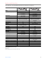
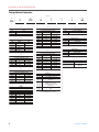
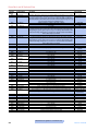
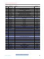
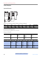
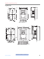
PowerFlex 4 and 40 Technical Data
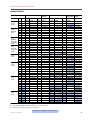
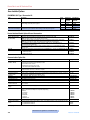
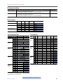
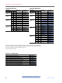
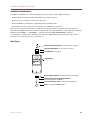
Parameter Descriptions
Parameter
Number
Display Group
d001
d002
d003
d004
d005
d006
d007-d009
d010
d012
d013
d014
d015
d016
d017
d018
d019
d020
d021
d022
d023
d024
d025
d026
d028
Parameter Name
Description
Output Freq
Commanded Freq
Output Current
Output Voltage
DC Bus Voltage
Drive Status
Fault x Code
Process Display
Control Source
Contrl In Status
Dig In Status
Comm Status
Control SW Ver
Drive Type
Elapsed Run Time
Testpoint Data
Analog In 0-10V
Analog In 4-20mA
Output Power
Output Power Fctr
Drive Temp
Counter Status
Timer Status
Stp Logic Status
Output frequency present at T1, T2 & T3 (U, V & W)
Value of the active frequency command
Output current present at T1, T2 & T3 (U, V & W)
Output voltage present at T1, T2 & T3 (U, V & W)
Present DC bus voltage level
Present operating condition of the drive
A code that represents a drive fault
The output frequency scaled by parameter A099 [Process Factor]
Displays the source of the Start Command and Speed Reference
Status of the control terminal block control inputs
Status of the control terminal block digital inputs
Status of the communications ports
Main Control Board software version
Used by Rockwell Automation field service personnel
Accumulated time drive is outputting power
The present value of the function selected in parameter A102 [Testpoint Sel]
The present value of the voltage at I/O Terminal 13 (100.0% = 10 volts)
The present value of the current at I/O Terminal 15 (0.0% = 4 mA, 100.0% = 20 mA)
Output power present at T1, T2 & T3 (U, V & W)
The angle in electrical degrees between motor voltage and motor current
Present operating temperature of the drive power section
The current value of the counter when counter is enabled
The current value of the timer when timer is enabled
When P038 [Speed Reference] is set to 6 “Stp Logic”, this parameter will display the current step
logic profile as defined by parameters A140-A147 [Stp Logic x]
Displays the current value of the motor torque current as measured by the drive
Read Only
Read Only
Read Only
Read Only
Read Only
Read Only
Read Only
Read Only
Read Only
Read Only
Read Only
Read Only
Read Only
Read Only
Read Only
Read Only
Read Only
Read Only
Read Only
Read Only
Read Only
Read Only
Read Only
Read Only
20 to drive rated volts
10 to 240 Hz
15 to 400 Hz
0.0 Amps to (Drive Rated Amps x 2) in units of 0.1 Amps
0.0 to 240.0 Hz
0.0 to 400.0 Hz
0 to 240 Hz
0 to 400 Hz
6 settings; Keypad, 3-Wire, 2-Wire, 2-Wire Level Sensitive, 2-Wire High Speed, Comm Port
7 settings; Keypad, 3-Wire, 2-Wire, 2-Wire Level Sensitive, 2-Wire High Speed, Comm Port,
Momentary FWD/REV
8 settings; Ramp-Clear Fault, Coast-Clear Fault, DC Brake-Clear Fault, DC Brake w/ShutoffClear Fault, Ramp, Coast, DC Brake, DC Brake w/Shutoff
10 settings; Ramp-Clear Fault, Coast-Clear Fault, DC Brake-Clear Fault, DC Brake w/ShutoffClear Fault, Ramp, Coast, DC Brake, DC Brake w/Shutoff, Ramp Stop w/EM Brake Control-Clear
Fault, Ramp Stop w/EM Brake Control
6 settings; Drive Potentiometer, Internal Freq, 0-10V Input/Remote Potentiometer, 4-20 mA Input,
Preset Freq 0-3, Communications Port
8 settings; Drive Potentiometer, Internal Freq, 0-10V Input/Remote Potentiometer, 4-20 mA Input,
Preset Freq 0-7, Communications Port, Step Logic, Analog In Mult
0.0 to 600.0 seconds
0.1 to 600.0 seconds
Used to reset drive to factory default settings
Sets the voltage class of 600V drives, Low Voltage (460/480V) or High Voltage (575/600V)
Enables/Disables the Motor Overload Retention function.
Based on Drive Rating
60 Hz
60 Hz
Based on Drive Rating
0.0 Hz
0.0 Hz
60 Hz
60 Hz
Keypad
Keypad
d029
Torque Current
Basic Program Group
P031
Motor NP Volts
P032
Motor NP Hertz
P033
P034
Motor OL Current
Minimum Freq
P035
Maximum Freq
P036
Start Source
P037
Stop Mode
P038
Speed Reference
P039
Accel Time 1
P040
Decel Time 1
P041
Reset To Defalts
P042
Voltage Class
P043
Motor OL Ret
Advanced Program Group
A051
Digital In1 Sel
A052
Digital In2 Sel
16 settings; Not Used, Accel 2 & Decel 2, Jog, Auxiliary Fault, Preset Frequencies, Local, Comm
Port, Clear Fault, Ramp Stop Clear Fault, Coast Stop Clear Fault, DC Brake Clear Fault, Jog
Forward, Jog Reverse, 10V In Control, 20 mA In Control, Analog Invert
28 settings; Not Used, Accel 2 & Decel 2, Jog, Auxiliary Fault, Preset Frequencies, Local, Comm
Port, Clear Fault, Ramp Stop - Clear Fault, Coast Stop - Clear Fault, DC Brake - Clear Fault, Jog
Forward, Jog Reverse, 10V In Control, 20 mA In Control, PID Disable, MOP Up, MOP Down,
Timer Start, Counter In, Reset Timer, Reset Counter, Reset Timer and Counter, Logic In1, Logic
In2, Current Limit2, Analog Invert, EM Brake Release
Factory Default
Read Only
Ramp, CF (Clear Fault)
Ramp, CF (Clear Fault)
Drive Pot
Drive Pot
10.0 Secs
10.0 Secs
Ready/Idle
High Voltage (575/600V)
Disabled
Preset Freq
Shaded areas are applicable to PowerFlex 40 only.
Publication 22-TD001G
21