1
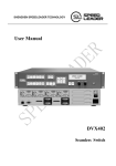
Speed Leader User Manual DVX602 LED Video Processor Contents About This Manual .................................................................................................. 3 Trademarks .............................................................................................................. 3 Safety Precautions ................................................................................................... 4 Accessories .............................................................................................................. 5 Product Models........................................................................................................ 6 Overview ................................................................................................................. 7 Panel ........................................................................................................................ 9 Front Panel ...................................................................................................... 9 Button Combinations ............................................................................. 11 Rear Panel...................................................................................................... 12 Application Scenarios............................................................................................ 13 Menu Introduction ................................................................................................. 14 Default Menu ................................................................................................. 14 Main Menu .................................................................................................... 15 Image Setting ......................................................................................................... 16 Image Setting Shortcut .................................................................................. 17 Window and Crop.................................................................................................. 18 Window Setting Shortcut............................................................................... 19 Crop ............................................................................................................... 19 Crop Setting Shortcut .................................................................................... 20 Output Resolution.................................................................................................. 21 LED ....................................................................................................................... 22 Function Setting .................................................................................................... 24 Overview ....................................................................................................... 24 Setting EDID ................................................................................................. 25 PIP ......................................................................................................................... 26 PIP Setting Shortcut....................................................................................... 28 Advanced Setting .................................................................................................. 29 Internal Test ................................................................................................... 29 System Information ............................................................................................... 30 Operation Guide .................................................................................................... 31 1 Splicing Setting ............................................................................................. 31 Function Setting..................................................................................... 31 Equal Splicing ....................................................................................... 32 Unequal Splicing ................................................................................... 33 PIP Mode Setting ........................................................................................... 34 PIP Parameter Setting ............................................................................ 34 Keying Mode ......................................................................................... 35 Presetting Scenarios............................................................................................... 36 Specifications ........................................................................................................ 38 Trouble Shooting ................................................................................................... 40 2 About This Manual Without written permission of the Company, no unit or individual may imitate, reproduce or copy this Manual, in full or in part. This Manual shall not be distributed or used for any commercial purposes in any form (electronic, mechanical, photocopy, recording or other possible forms). The product specifications and information mentioned in this Manual are for reference only and are subject to change without notice. Unless specifically agreed, this Manual is for guidance only. No statement or information in this Manual constitutes guarantee in any form. Trademarks VGA and XGA are registered trademarks of IBM. VESA is a trademark of Video Electronics Standards Association. HDMI mark and High-Definition Multimedia Interface are trademarks of HDMI Licensing LLC. 3 Safety Precautions This device must be connected to a ground wire. This device must use voltage with rated power. Ensure the error of the input voltage is ±10%. Do not connect the AC power cable to an AC power cable that may cause excessive noise. Use this device in an environment with an ambient temperature between -10℃ and 40℃ and a relative humidity of 90% or below. Do not use this device in certain special circumstances, such as places near heat sources, which may cause damage of the device due to overheat. Use this device in a place with good ventilation, and prevent the vent of the device from being blocked. Do not expose this device to any place where accidental collision or vibration may occur. If it will be used in a place with vibration, reinforce the device. Do not place foreign objects, e.g. water or metal into the device, which will cause damage to the device and result in a fire. In case any irregular or abnormal phenomenon is found, switch off the power immediately, disconnect the AC power cable, and handle the phenomenon by referring to “Troubleshooting Guidance”. In case of any damage, do not disassemble the device. Contact the maintenance department of Speed Leader. 4 Accessories Item Name Qty DVX602 1 AC power cable 1 User manual 1 Qualified Certificate 1 Warranty Card 1 M3*6 round head screw 2 Φ5*18 copper cylinder 2 Table 4-1 Package content * Accessories can be defined based on customer requirements. 5 Product Models Model Description DVX602 Basic DVX602S Basic + Expanding 1x3G - SDI input DVX602SD Basic + Expanding 1x3G - SDI input, Expanding Program output DVI/VGA DVX602SF Basic + Expanding 1x3G - SDI input, Expanding Program output SDI/DVI/VGA/VID DVX602F Basic + Program output SDI/DVI/VGA/VID DVX602D Basic + Expanding Program output DVI/VGA DVX602T Basic + Expanding 2x3G - SDI input DVX602TD Basic + Expanding 2x3G - SDI input, Expanding Program output DVI/VGA DVX602TF Basic + Expanding 2x3G - SDI input, Expanding Program output SDI/DVI/VGA/VID Table 4-2 Product models 6 Overview DVX602 series video processor is a high-performance LED video processor that uses the 30-bit digital signal processing technology, advanced deinterlacing signal processing and real Seamless Switch technology for professional demonstration. It supports 1080p and 1920x1200@60Hz full HD resolution output (up to 2304x1152@60Hz). Point-to-point pixel adjustment can be realized. It can receive several types of video input formats, such as 3G-SDI, HDMI, DVI, VGA, and SD video. Splicing LED Video Processor DVX602 Series Video Processor supports signal interconnection. Through simple splicing setup, ultra high resolution displaying can be realized without an expensive splicing controller. Seamless Switch The seamless switch between single-window and dual-window function and fade-in fade-out effects are provided to enhance and present demonstration pictures of professional quality. Internal Test Patterns for Calibration and Setup A number of test patterns are provided, including square, color bar, gray scale, alternate pixel, white field, full red, full green, full blue, etc. Picture-in-picture Any Size Any Position The position, size, etc. of picture-in-picture are adjustable and can be controlled arbitrarily. 7 Broadcast-Quality Multi-Stage Scaling Engine DVX602 Series Video Processor uses high performance 30-bit Faroudja® DCDI multi-stage scaling engine to convert the resolution of pictures to a lower or higher one for signals of various definitions, as well as the professional ACC and ACM video processing engine to present you with a completely new visual enjoyment. Input Interfaces 2 BNC inputs, 2 VGA inputs, 2 DVI inputs, 1 HDMI input, 1 RS232 communication port, 2 3G-SDI inputs (optional). Output Interfaces DVX602 provides three independent video outputs for preview, program, and LED. Convenient Keys on the Panel An intuitive LCD interface and the clear key indicators simplify the installation and control of the system. Preset Scenarios DVX602 supports multiple scenarios to be saved and invoked, which is easy to realize. 8 Panel Front Panel 1 2 SN Name 1 LCD display 5 6 7 Operation Show menu and current information. Knob (up) Select up/down/left/right menus and adjust the parameters. Press this knob for confirmation. Knob (down) Select up/down and adjust the parameters. Press this knob for confirmation. MENU Enter the main menu or return to the previous menu. ENTER Confirm an operation or switch between submenus. It can be used in combination with other buttons for specific function as well. PIP Picture-in-picture button. Press and hold this button for one second to enter PIP parameters setting menu. Press the ENTER button to switch the current operation interface. CROP Cropping button. Press and hold this button for one second to enter CROP parameters setting menu. Press the ENTER button to switch the current operation interface. 2 3 4 3 4 9 PART BRIGHT Adjust image brightness and contrast PRESET Scenario switch button. Press the ENTER button to switch the current operation mode. FREEZE Freeze or unfreeze a window. In scenario mode, this operation is realized by the number key 1. HDMI Select HDMI channel. In scenario mode, this operation is realized by the number key 6. VID1 Select composite video 1 channel. In scenario mode, this operation is realized by the number key 2. VID2 Select composite video 2 channel. In scenario mode, this operation is realized by the number key 7. VGA1 Select VGA 1 channel. In scenario mode, this operation is realized by the number key 3. VGA2 Select VGA 2 channel. In scenario mode, this operation is realized by the number key 8. DVI1 Select DVI 1 channel. In scenario mode, this operation is realized by the number key 4. DVI2 Select DVI 2 channel. In scenario mode, this operation is realized by the number key 9. SDI1 Select SDI 1 channel. In scenario mode, this operation is realized by the number key 5. SDI2 Select SDI 2 channel. In scenario mode, this operation is realized by the number key 0. PGM Preview and program switch CUT Immediately switch FADE fade-in and fade-out 5 6 7 Full or Part shortcut key. Press and hold this button for one second to enter window parameters setting menu. Press the ENTER button to switch the current operation interface. BLACK Program/LED output channel black screen Table 7-1 Descriptions of front panel 10 Button Combinations ENTER + CROP : Restore the crop parameters for selected preview/program output back to default values. Reset the crop parameters of the selected preview/program to default. ENTER + PART : Restore the window parameters for selected preview/program output back to default values. Reset the window parameters of the selected preview/program to default. ENTER + BRIGHT : Restore the image brightness/contrast parameters for selected preview/program output back to default values. Reset the brightness/contrast of the selected preview/program to default. 11 Rear Panel 1 3 2 4 5 7 6 SN 8 Port 1 Video input DVX602 can receive 2* VGA, 2*DVI, 1*HDMI, 2* VID and 2*SDI (optional) signal source simultaneously. 2 COM port One RS-232 port 3 Program output 4 DVI loop-out port One DVI 1 loop-out port 5 LED output Two DVI-I output ports 6 Preview output Two DVI-I output ports 7 Sending card interface AC power socket 8 Power switch Expanding program output DVI/VGA and SDI/DVI/VGA/VID Reserved for installing a sending card 100~240VAC, 50Hz/60Hz "I" indicates power-off. power-on; Table 7-2 Description of rear panel 12 "O" indicates Application Scenarios Application 1 Application 2 13 Menu Introduction Default Menu DVX602 provides a convenient menu system. Figure 9-1 shows the default menu that appears after DVX602 is powered on. The user can observe the current preview signal source, program signal source and other important information via the default menu. Power-on Speed Leader DVX602 Preview Program DVI2 DVI1 No sync FADE No sync 1.0S MENU Main menu Figure 9-1 Menu Flowchart 14 Main Menu Under the default menu, press the MENU button to enter the main menu of DVX602. Figure 9-2 is the first-level menu of the main menu system displayed on LCD and the user can enter the next menu quickly by the rotary knob. Turn the knob to switch to next menu item Figure 9-2 Main menu The main menu is composed of 8 submenus and they are shown in two pages. Turn the knob to select a menu item and press ENTER or press the knob to enter the submenu. Press ENTER again to return to the main menu. Press MENU return to the previous menu. ※Note: Under the main menu, both the knobs have the same function (switching to a preceding or next menu item). When you switch to the last menu item, continuing to turn the knob will not go back to the first menu item. 15 Image Setting Figure 10-1 Image setting submenu Item Operation Output Channel Knob adjustment: Preview/Program/LED/PIP Brightness Knob adjustment: 0~64~127 Contrast Knob adjustment: 0~64~127 Color Knob adjustment: 0~64~127 Amplitude CutOff Reset Red Knob adjustment: 0~255 Green Knob adjustment: 0~255 Blue Knob adjustment: 0~255 Red Knob adjustment: 0~31 Green Knob adjustment: 0~31 Blue Knob adjustment: 0~31 Press ENTER or press the knob to enter the Resetting menu and restore the image parameters for the selected output channel back to default values. Table 10-1 Parameters of the image setting submenu 16 Note: Image brightness, contrast, color saturation, and color can be saved separately in the parameters of the signal source which the output selected. The parameters of each input signal source is saved without interference. For example, brightness and contrast for preview output VGA1 are 78 and 87 respectively; brightness and contrast for preview output VGA2 are 65 and 68 respectively; brightness and contrast for LED output VGA1 are 69 and 70 respectively; brightness and contrast for LED output VGA2 are 72 and 83 respectively. Image Setting Shortcut To set image parameters in a convenient way, press BRIGHT to enter the shortcut menu. Figure 10-2 Image setting shortcut menu Figure 10-2 shows the brightness and contrast for the selected preview output channel. Turn the knob to change the values. Press PGM to switch between preview outputs and program outputs. Press ENTER + BRIGHT to reset the image brightness/contrast parameters for selected preview/program channel back to default values. 17 Window and Crop Figure 11-1 Window and crop submenu Item Operation Output Channel Knob adjustment: Preview/Program/LED/PIP Window Adjust Knob adjustment: Enable/Disable Window H Width Knob adjustment Window V Height Knob adjustment Window H Start Knob adjustment Window V Start Knob adjustment Window Reset Press ENTER or press the knob to enter the Resetting menu and reset the window parameters for the selected output channel back to default values. Crop Adjust Knob adjustment: Enable/Disable Crop H Width Knob adjustment Crop V Height Knob adjustment Crop Reset Press ENTER or press the knob to enter the Resetting menu and reset the crop parameters for the selected output channel back to default values. Table 11-1 Parameters of the window and crop submenu 18 Note: Window parameters and crop parameters can be saved separately in the parameters of the signal source which the output selected. The parameters of each input signal source is saved without interference. Window Setting Shortcut To set window parameters in a convenient way, press PART – the partial window switch. The switch is turned on when the button is lighted up. Press and hold PART for one second to enter the shortcut menu. Figure 11-2 Window shortcut menu Figure 11-2 shows the window parameters of the selected signal under the preview output channel. Turn the knob to change window width and height. Press ENTER to switch between window size and start position; press PGM to switch between preview outputs and program outputs. Press ENTER + PART to reset the window parameters of the signal which the preview/program selected. Crop This function is to display the cropped part of an image. Users can change crop size and position. 19 Crop Setting Shortcut To set crop parameters in a convenient way, press CORP – the crop window switch. The switch is turned on when the button is lighted up. Press and hold CORP for one second to enter the shortcut menu. Figure 11-3 Crop shortcut menu Figure 11-3 shows the crop parameters of the selected signal under the preview output channel. Turn the knob to change width and height of an image part to be cropped. Press ENTER to switch between crop size and start position; press PGM to switch between preview outputs and program outputs. Press ENTER + CROP to reset the crop parameters of the signal source which the preview /program selected. 20 Output Resolution Figure 12-1 Output resolution submenu Item Operation Press ENTER to enter the resolution menu Preview Timing Turn the knob and press ENTER or press the knob SDI/DVI/VGA Timing Press ENTER to enter the resolution menu Turn the knob and press ENTER or press the knob Program Timing CVBS Timing Press ENTER to enter the resolution menu Turn the knob and press ENTER or press the knob Press ENTER to enter the resolution menu LED Timing Turn the knob and press ENTER or press the knob Table 12-1 Parameters of the output resolution submenu 21 LED Figure 13-1 LED submenu 22 Item Screen Size Operation Window Adjust Knob adjustment : Enable/Disable Window H Width Turn the knob Window V Height Turn the knob Window H Start Turn the knob Window V Start Turn the knob Window Reset Press ENTER or press the knob to enter the Resetting menu and restore the spliced window parameters to default values. Output Channel LED Splice Mode Splicing Setting Equal Splice Setting Unequal Splice Setting Turn the knob: Disable/ Equal / Unequal H Splice Unit Turn the knob: 1~10 V Splice Unit Turn the knob: 1~10 Splice Position Turn the knob: 1~100 H Total Width Turn the knob V Total Height Turn the knob H Splice Start Turn the knob V Splice Start Turn the knob Genlock Turn the knob: Freerun/V Lock Input Channel Turn the knob: Program/DVI 1/DVI 2 Table 13-1 Parameters of the LED submenu 23 Function Setting Figure 14-1 Function setting submenu Overview DVX602 provides EDID definable functions for users to set required resolution for an output device, such as a PC or other image output device. 24 Setting EDID Enter the EDID setting menu and select a required input channel. Press ENTER or press the knob to enter the EDID menu. Select required parameters and press ENTER or press the knob to change parameters. Item Operation DVI1 EDID DVI2 EDID EDID Setting Press ENTER to enter the resolution menu Turn the knob and press ENTER or press the knob VGA1 EDID VGA2 EDID Press ENTER to enter the resolution menu Turn the knob and press ENTER or press the knob Output Channel Auto Adjust VGA Setting Turn the knob: preview/program Press ENTER or press the knob H Start Turn the knob V Start Turn the knob H Clock Turn the knob Clock Phase Turn the knob Reset Press ENTER or press the knob to enter the Resetting menu and reset the VGA parameters for the selected output channel back to default values. 25 Equalizer Setup DVI1 input Turn the knob: 0~63 DVI2 Input Turn the knob: 0~63 Preview Output 1 Turn the knob: 0~47 Preview Output 2 Turn the knob: 0~47 Program Output 1 Turn the knob: 0~47 Program Output 2 Turn the knob: 0~47 Table 14-1 Parameters of the function setting submenu PIP Figure 15-1 PIP submenu 26 Item Operation PIP Input Turn the knob: DVI1/DVI2 PIP Mode Turn the knob: PIP/Key Key Color Key User Define Turn the knob: Black, White, Red, Green, Blue, Black Invert, White Invert, Red Invert, Green Invert, Blue Invert, User Red Max Turn the knob: 0~15 Red Min Turn the knob: 0~15 Green Max Turn the knob: 0~15 Green Min Turn the knob: 0~15 Blue Max Turn the knob: 0~15 Blue Min Turn the knob: 0~15 Invert Mode Enable/Disable Reset Press ENTER or press the knob to enter the Resetting menu and reset the keying parameters to default values. Table 15-1 Parameters of the PIP submenu 27 PIP Setting Shortcut To set PIP parameters in a convenient way, press and hold PIP for one second to enter the PIP shortcut menu. PIP is a switch and it will be turned on when the button is lighted up. Figure 15-2 PIP shortcut menu Figure 15-2 shows the PIP shortcut menu. Press ENTER to switch between PIP window, crop, window and crop, and input & mode. Turn the knob to change parameter values. Note: Pressing ENTER + PIP will not reset PIP parameter values. 28 Advanced Setting Figure 16-1 Advanced setting submenu Item Operation Fan Control Turn the knob: On/Off Test Pattern Turn the knob: Off/White/Red/Green/Blue RS232 Baud Rate Turn the knob: 9600/19200/38400/115200 Key lock Turn the knob: Off/ On (press and hold ENTER for three seconds to unlock the key panel) Table 16-1 Parameters of the advanced setting submenu Internal Test After an LED display is finished, users may want to test the display screen. DVX602 provides different patterns for users to detect defective pixels and blind spots and check LED dot matrix for misalignment. Refer to the following step to adjust the display screen. Output test patterns: Under the main menu, choose "Advanced setting"→"Test patterns" and turn the knob to change pattern color. 29 System Information Figure 17-1 System information submenu Item Operation Language Chinese/English System Version Press ENTER or turn the knob to view the hardware & software version information System Reset Press ENTER or turn the knob to reset all system parameters to default values Table 17-1 Information of the system information submenu 30 Operation Guide Splicing Setting A splicing solution is used if a single video processor cannot drive an ultra-HD LED display. Splicing method is unlimited and can be applied to different LED systems. Signal Connection LED units are spliced using one input, that is a channel corresponds to one signal source only (inputs are realized by signal loop or signal distribution). The signal is processed and then output to an LED display. The following takes DVI input as an example to describe the connection method: Part 1 DVI Part 2 Part 3 DVI1 DVI1 DVI1 DVI1 LOOP DVI1 LOOP DVI1 LOOP Processor 1 Processor 2 Figure 18-1 Processor 3 Function Setting DVX602 supports equal splicing and unequal splicing. In equal splicing, horizontal pixels and vertical pixels are equal; in unequal splicing, pixels of different parts are unequal. 31 Equal Splicing 1024×3 768 Part 1 Part 2 Screen Size Screen Size Window H Width =1024 Window V height =768 Splice Part 3 Mode → Window H Screen Size Width Window H Width =1024 =1024 Window V Height Window V Height =768 =768 Splice Mode → Splice Mode → Equal Splice Setting Equal Splice Setting Equal Splice Setting H Splice Unit=3 H Splice Unit =3 H Splice Unit =3 V Splice Unit=1 V Splice Unit=1 V Splice Unit=1 Splice Position =1 Splice Position =2 Splice Position =3 DVX602 1 DVX602 2 Figure 18-2 DVX602 3 As shown in the preceding figure, under main menu, choose "LED"→ "Screen Size" and change " Window H Width" to "1024"; " Window V Height" to "768", "Splice Mode" to "Equal", " H Splice Unit" to "3", "V Splice Unit" to "1", and " Splice Position" to " incremental left to right". 32 Unequal Splicing 3640 1040 Part 1 1872×1040 Part 2 1768×1040 Screen Size Screen Size Window H Width=1872 Window H Width =1768 Window V Height=1040 Window V Height=1040 Window H Start=0 Window H Start=0 Window V Start=0 Window V Start=0 Splice mode → Unequal Splice mode →Unequal Unequal Setting Unequal Setting Total Width =3640 Total Width=3640 Total Height =1040 Total Height =1040 H Splice Start=0 H Splice Start=1872 V Splice Start=0 V Splice Start=0 DVX602-1 DVX602-2 Figure 18-3 As shown in the preceding figure, under main menu, choose "LED" -> "Screen Size" and change DVX602-1 window " Window H Width" to "1872", " Window V Height" to "1040", "window H/V start" to "0", "splice mode" to "Unequal", "H Total Width" to "3640", "V Total Height" to "1040", and "H/V Splice Start" to "0". Change DVX602-2 window "H Width" to "1768", "V Height" 33 to "1040", "Window H Start" to "0", "Window V Start" to "0", "Splice Mode" to " Unequal", "H Total Width" to "3640", "V Total Height" to "1040", "H splice Start" to "1872", and "V Splice Start" to "0". PIP Mode Setting PIP adopts the digital technology to realize concurrent display of two programs, allowing one or more compressed sub-screens to be displayed on the main screen so that you can monitor channels while watching the main screen. PIP Parameter Setting Press PIP (this switch is turned on when the PIP button is lighted up), enter "Window & Crop", and change "Output Channel" to "PIP", "Window Adjust" to "Enable", " Window H Start" to "364", " Window V Start" to "250", " Window H Width" to "480", and " Window V Height" to "320". The following figure shows the adjustment result. Input DVI1 H Start 364 V Start 250 H Width 480 V Height 320 320 Figure 18-4 e 18-4 Note: Only DVI1 and DVI2 supports PIP output. 34 Keying Mode Keying is an extended function of PIP. This is realized by subtracting specified color from image color input through a PIP channel. Keying is used to produce simple special effect and add subtitles. Adding Subtitle PIP channel + Main screen channel = Subtitle Figure 18-5 Under the main menu, choose "PIP" and change " PIP Mode" to "Key" and " Key Color" to "Black" (by default, this parameter is set to " Black "). According to the preceding figure, enter white words on the black background through a PIP channel and overlap the screen with the main screen to get the subtitle effect. Description of keying color: Black: keying black Red: keying red Blue: keying blue White inversion: reserving white Green inversion: reserving green White: keying white Green: keying green Black inversion: reserving black Red inversion: reserving red Blue inversion: reserving blue 35 Presetting Scenarios Preset modes are various application scenarios that users can invoke to use without repeatedly setting the scenarios. This function helps improve working efficiency. A preset scenario must be configured with channel mode, image quality image, capture, window and PIP associated parameters. The following will describe how to save and invoke a preset scenario: Press PRESET to enter the preset mode menu. As shown in the preceding figure, press PGM to switch between preview outputs and program outputs and press ENTER to switch scenarios. Saving a Scenario After a scenario is set, press ENTER to switch to saving mode and press a number key (0~9) to save the scenario as a number. In this case, is changed to . 36 Invoking and Erasing a Scenario Under the preset mode menu, press ENTER to switch to invocation/erasing mode. If there are scenarios available, The symbol which is corresponding to numbers is . Press these numbers to recall or erase the scenarios. Note: If there are preset scenarios available, changing resolutions of preview outputs or program outputs will cause all the scenarios to be cleared. 37 Specifications Video Input Interface Qty Connecto r DVI 2 DVI-I DVI1.0, in compliance with VESA standard, PC to 1920×1080 VGA 2 DB15 In compliance with VESA standard, PC to 1920×1080 BNC PAL/NTSC/SECAM 1Vpp±3DB(0.7V Video+0.3V Sync) 75 ohm VID 2 HDMI 1 HDMI Specifications DVI1.0,HDMI1.3 downwa rd c o mpatible PC to 1920×1080,HD to 1080p 1080p 60/50/30/25/24 SDI (optional) 1080i 60/50 2 BNC 720p 60/50 625i 525i Preview output Qty 1 VGA channel and 2DVI channels Connector DVI-I Stand ard VESA Resolu tio n 640x480@60Hz 800x600@60Hz 1024x768@60Hz 1280x1024@60Hz 1366x768@60Hz 1440x900@60Hz 1600x1200@60Hz 1680x1050@60Hz 1920x1080@60Hz 1920x1200@60Hz 2048x1152@60Hz 1920x1080@50Hz 1280x720@50Hz 38 Program output (optional) Output Connector DVI VGA SDI VID DVI-I DB15 BNC BNC 1 1 1 1 Qty VGA/DVI 640x480@60Hz 800x600@60Hz 1024x768@60Hz 1280x1024@60Hz 1366x768@60Hz 1440x900@60Hz 1600x1200@60Hz 1680x1050@60Hz 1920x1080@60Hz 1920x1200RB@60Hz 1080p 60/59.94/50/30/29.97/25/24/23.98 Resolu tio n 1080i 60/59.94/50 SDI/DVI 720p 60/59.94/50 625i 525i PAL VID NTSC LED output Qty 1 VGA channel and 2 DVI channels Connector DVI-I Stand ard VESA Resolu tio n 640x480@60Hz 800x600@60Hz 1024x768@60Hz 1280x1024@60Hz 1366x768@60Hz 1440x900@60Hz 1600x1200@60Hz 1680x1050@60Hz 1920x1080@60Hz 1920x1200@60Hz 2048x1152@60Hz 2560x960@60Hz 1920x1080@50Hz 1280x720@50Hz 2304x1152@60Hz 1920x1280@60Hz 1536x1536@60Hz 1280x1920@60Hz User Define General parameters Weight Dimensions 4.7Kg 6.5cm(H)×44cm(W)×32cm(L) Power supply 100VAV-240VAC 50/60Hz Max. power Working temperature 40W 0°C~45°C 39 Trouble Shooting Problems may be encountered during installation or use. Here, the user can follow the steps below to remove the troubles; if the steps below still cannot fix the problems for you, please contact the local dealer. 1. The equipment has no image and the indicator light doesn’t work. Check whether the power supply is connected well and the power switch is turned on. 2. LCD screen on the key panel has data displayed, but no image output. Check whether the signal is connected correctly. Check whether the equipment supports the resolution and refresh the frequency. Reset the equipment to factory default settings. 3. VGA picture cannot be displayed on the full screen or is deflected. Check whether VGA wire is up to standard or overlong. Open the menu: System →VGA settings→ Automatic adjustment; and hit VGA automatic adjustment. Adjust the picture manually in VGA settings. 4. HDMI/DVI output picture cannot be displayed on the full screen. Reset output resolution of the equipment. Check whether output resolution of PC or notebook is identical to the resolution received by the splicer. Check whether desktop wallpaper is too small. 40 Hotline: 400-6286-959 SHENZHEN SPEEDLEADER TECHNOLOGY CO., LTD. Tel.: 0755-26588939 Fax: 0755-26586619 Postal code: 518052 Address: Floor 6, Baocheng Tech Building , Majialong Industy, Nanshan District, Shenzhen, China Website: http://www.jstron.com E-mail: [email protected]