1
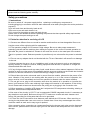
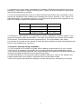
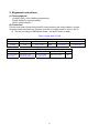
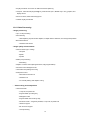
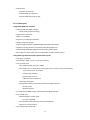
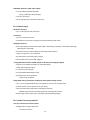
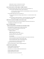
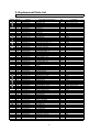
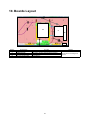
ORDER NO.MTNC120449CE B01 Canada: B61 LCD TV Model No. TC-L32C5 TC-32LC54 TC-L32C5X TC-L3252C ©Panasonic Corporation 2012. Unauthorized copying and distribution is a violation of law. CONTENTS 1. Safety precautions .................................................................................................3 2. Alignment instructions and method of software upgrading.....................................5 3. Working principle analysis of the unit ................................................................... 14 4. Block diagram ......................................................................................................15 5. IC block diagram ..................................................................................................16 6. Wiring diagram ...................................................................................................28 7. Troubleshooting guide..........................................................................................30 8. Exploded View .....................................................................................................34 9. Replacement Parts List........................................................................................36 10. Boards Layout....................................................................................................39 2 Attention: This service manual is only for service personnel to take reference with. Before servicing please read the following points carefully. Safety precautions 1. Instructions Be sure to switch off the power supply before replacing or welding any components or inserting/plugging in connection wire Anti static measures to be taken (throughout the entire production process!): a) Do not touch here and there by hand at will; b) Be sure to use anti static electric iron; c) It’s a must for the welder to wear anti static gloves. Please refer to the detailed list before replacing components that have special safety requirements. Do not change the specs and type at will. 2. Points for attention in servicing of LCD 2.1 Screens are different from one model to another and therefore not interchangeable. Be sure to Use the screen of the original model for replacement. 2.2 The operation voltage of LCD screen is high voltage. Be sure to take proper measures in protecting yourself and the machine when testing the system in the course of normal operation or right after the power is switched off. Please do not touch the circuit or the metal part of the module That is in operation mode. Relevant operation is possible only one minute after the power is switched off. 2.3 Do not use any adapter that is not identical with the TV set. Otherwise it will cause fire or damage to the set. 2.4 Never operate the set or do any installation work in bad environment such as wet bathroom, laundry, kitchen, or nearby fire source, heating equipment and devices or exposure to sunlight etc. Otherwise bad effect will result. 2.5 If any foreign substance such as water, liquid, metal slices or other matters happens to fall into the module, be sure to cut the power off immediately and do not move anything on the module lest it should cause fire or electric shock due to contact with the high voltage or short circuit. 2.6 Should there be smoke, abnormal smell or sound from the module, please shut the power off at once. Likewise, if the screen is not working after the power is on or in the course of operation, the power must be cut off immediately and no more operation is allowed under the same condition. 2.7 Do not pull out or plug in the connection wire when the module is in operation or just after the power is off because in this case relatively high voltage still remains in the capacitor of the driving circuit. Please wait at least one minute before the pulling out or plugging in the connection wire. 2.8 When operating or installing LCD please don’t subject the LCD components to bending, twisting or extrusion, collision lest mishap should result. 2.9 As most of the circuitry in LCD TV set is composed of CMOS integrated circuits, it’s necessary to pay attention to anti statics. Before servicing LCD TV make sure to take anti static measure and ensure full grounding for all the parts that have to be grounded. 2.10 There are lots of connection wires between parts behind the LCD screen. When servicing or moving the set please take care not to touch or scratch them. Once they are damaged the screen would be unable to work and no way to get it repaired. If the connection wires, connections or components fixed by the thermo tropic glue need to disengage when service, please soak the thermo tropic glue into the alcohol and then pull them out in case of damage. 3 2.11 Special care must be taken in transporting or handling it. Exquisite shock vibration may lead to breakage of screen glass or damage to driving circuit. Therefore it must be packed in a strong case before the transportation or handling. 2.12 For the storage make sure to put it in a place where the environment can be controlled so as to prevent the temperature and humidity from exceeding the limits as specified in the manual. For prolonged storage, it is necessary to house it in an anti-moisture bag and put them altogether in one place. The ambient conditions are tabulated as follows: Temperature Humidity Scope for operation 0 ~ + 40 oC Scope for storage -20 ~ + 60oC Scope for operation 20% ~ 90 % Scope for storage 5% ~ 90% 2.13 Display of a fixed picture for a long time may result in appearance of picture residue on the screen, as commonly called “ghost shadow”. The extent of the residual picture varies with the maker of LCD screen. This phenomenon doesn’t represent failure. This “ghost shadow” may remain in the picture for a period of time (several minutes). But when operating it please avoid displaying still picture in high brightness for a long time. 3. Points for attention during installation 3.1 The front panel of LCD screen is of glass. When installing it please make sure to put it in place. 3.2 For service or installation it’s necessary to use specified screw lest it should damage the screen. 3.3 Be sure to take anti dust measures. Any foreign substance that happens to fall down between the screen and the glass will affect the receiving and viewing effect 3.4 When dismantling or mounting the protective partition plate that is used for anti vibration and insulation please take care to keep it in intactness so as to avoid hidden trouble. 3.5 Be sure to protect the cabinet from damage or scratch during service, dismantling or mounting. 4 2. Alignment instructions (1) Test equipment VG-859 (YPbPr, VGA, HDMI signal generator) FLUKE 54200(TV signal generator) CA210 (white balancer) (2) Power test Connect main board, power board and IR board according the wiring diagram, connect the power and press power key (Remote controller or Keypad) button to turn on the TV. a) Test the pin voltage of P802/power board , the data is shown in table1: Table1 voltage data of P802 For 32” P802 Pin1,2 Pin3,4 Voltage GND 11.4V~12.6V Pin5,6,7 GND Pin8,9 Pin10,11 11.4V~12.6V 4.75V~5.25V For 32” Pin12 On:2.5V-5.25V Off: 0-0.5V Pin13 Normal:0V~0.5V Abnormal :Open drain Pin 14 Pin15 On:2.5V-5.25V Off: 0-0.5V Duty 20%~100% 5 Pin16 NC (3) Alignment flow-chart The alignment flow-chart is shown as fig-1 Check if DDC, HDCP KEY, FLASH are written Combined test for general assembly White balance adjustment Connect to the center signal source and check each Function of TV (station leaking, analog control, etc.) Check the output of earphone and speaker. Input AV signal and check the function Input HD signal and check the function of YPbPr Input VGA signal and check if the display is normal, check the function (analog control), horizontal/vertical center, etc. Input USB signal and check if the display is normal, check the function (analog control), horizontal/vertical center, etc. Input HDMI signal and check if the display is normal, check the function (analog control), horizontal/vertical center, etc. Preset ex-factory Check the accessories and packing Fig-1 adjustment flow-chart 6 (4) Adjustment instruction At any input source then press the “←”, “EXIT” and “OK” (Remote control within 1 sec) to enter factory mode During Factory menu, if “MENU” key is pushed, system will exit factory mode. 4-1. Source Calibration 4-1.1. Set the signal generator to input sources Component on LCD-TV; ASTRO-859 signal setting to NTSC-M (PG2 mode Timing 924 and Pattern 984 SMPTE Color Bar.) 4-1.2. Entering into factory Mode: Press up or down key of remote control to select “Source Calibration”, Press 「OK」 key to enter the item. -> Source calibration performed automatically when finished that will show OK. Repeat step 2 to do VGA input sources, ASTRO-859 signal setting to1024X768 60Hz. (PG2 mode: Timing 963 and Pattern 942 16step H-grayscale + white border.) 7 4-2. Color Temperature Adjustment & Check 4-2.1. Set the signal generator to RGB, 1024*768, 60HZ(ASTRO-859: PG1 856), Level: 77(30%) or 178(70%). Full white pattern. (RGB gain and offset all should not over 128,and one of RGB gain and offset have to be setting on 110. ) 4-2.2. Press up or down key of remote control to select “Cool”, Press 「ENTER」 key to enter the item. RGAIN, GGAIN, BGAIN, ROFFSET, GOFFSET, BOFFSET, drive values are set for Warm, Normal, and Cool independently. 4-2.3. Select 「Warm」 Step 1.First Turning Gain parts of RGB. (1) Warm spec.: x= 0.318±0.005 y= 0.331±0.005 (2) If the x and y value are larger than specification, Decrease R GAIN drive from default value. Increase B GAIN drive from default value. (3) If the x or y or both x and y value is/are smaller than specification. Decrease B GAIN drive from default value (4) According to a x and y value, please following adjustment of (4)-1 or (4)-2. (4)-1 If x value is higher than spec Decrease R GAIN drive from default value. Increase B GAIN drive from default value. (4)-2 If y value is higher than spec, Decrease B GAIN drive from default value Step 2.When finish Gain parts, then turning OFFSET parts Select 「Normal」 (1) Medium spec.: (Same as the Gain session) x= 0.289±0.005 y= 0.306±0.005 (2) If the x and y value are larger than specification, Decrease R OFFSET drive from default value. Increase B OFFSET drive from default value. (3) If the x or y or both x and y value is/are smaller than specification. 8 Decrease B OFFSET drive from default value (4) According to a x and y value, please following adjustment of (4)-1 or (4)-2. (4)-1 If x value is higher than spec Decrease R OFFSET drive from default value. Increase B OFFSET drive from default value. (4)-2 If y value is higher than spec, Decrease B OFFSET drive from default value Step 3.When finishing OFFSET parts, then recheck Gain parts .unitl Both of them meet the target specification Step 3. Than select 「Cool」 using same way to adjust the setting. 4-2.4. Exit Factory Mode: After finish adjusting color temperature press [MENU] to exit factory mode. (5) Items of Factory menu When in PC/ Component/ Video (Composite)/ ANT inputs then press the “Left -> Exit -> Enter” key of remote control to enter factory mode.. During Factory menu, if “MENU” or “EXIT” key is pushed, system will exit factory mode. Press up and down key can move high light item from Color Temperature -> Timer Clear -> Preset Channel>NVRAM Clear-> Full Power -> Source Calibration -> Reset to Default -> RF Burn In -> USB F/W Upgrade -> UART Enable-> Bypass Gamma. The Timer Clear, NVRAM Clear and Reset to Default items will have a check dialog “yes or no” to do or not. Push “Enter” key can select high light item function. (Press left and right can adjust value) Display panel Burn in Time on the bottom. Display model name, firmware version and released date on top. 1) Factory Color Temp data edit Press up or down key can select high light item function Press enter key to enter the item. -Color temp default preset No (Warm, Medium, Cool). -R, G, B data for each preset Press “Up” or “Down” key to select “R”, “G”, “B” item Press “Left” or “Right” key to set the “R”, “G”, “B” value Press “MENU” or “EXIT” item to exit to factory mode 2) Timer Clear Reset the timer which records hours of LCD panel burn in This item will have a check dialog “yes or no” to do or not. - Time in factory mode: Time function shall be displayed automatically. Saving the total time of system 9 power on (LCD turn on), and count the time automatically. The timer is continuous and saved (per 10 minutes) forever, unless it will be reset by doing “Timer Clear”. 3) Preset channel Load preset channel for production line. (Refer 4.4.4 Preset channel table). 4) NVRAM CLEAR Initialize program’s default values to NVRAM for following adjustment items accuracy. In factory mode it is the first and important step to make sure all values are default value and correct - Reset settings: Gamma table, Channel table (Favorite channel, Channel label etc.), Model table (H/V Position, Clock, Phase), Source dependent setting (Contrast, Brightness etc.), Common setting (Volume, Language etc.), Parental Control (Rating, Password etc), Closed Caption. To avoid a mistake initial process after factory setting is done. This item will have a check dialog “yes or no” to do the initial or not. Notice: After this item is processed then the DUT needs to be powered off then AC powered off. 5) Full power This is for power consumption testing. To measure the maximum power consumption of TV set, we adjust the value of following items to maximum. - Video: Contrast maximum value, Brightness maximum value, Backlight maximum value. - Audio: Volume maximum value, Bass default value, Treble default value. Press enter key to turn on Full Power and OSD stay display until press enter key to recover from Full Power 6) Source Calibration Source Calibration (gain/offset) must be adjusted color by firmware automatic adjustment in PC, Composite and Component input source. This item will have a result dialog “OK” or “NG”. 7) Reset to Default Reset all settings of OSD menu to default value. - Reset settings: Channel table, Model table (H/V Position, Clock, Phase), Source dependent setting (Contrast, Brightness etc.), Common setting (Volume, Language etc.), Parental Control (Rating, Password etc), Closed Caption. 8) RF Burn In Use “snow” pattern for burn in. Selected items are “On” and “Off”. While turn on burn in mode, firmware will automatically turn off “Auto power off” function. If there is no power supply suddenly, firmware will re-enter burn in mode automatically when power supply is back Pressed the “Power” key, firmware will automatically turn off burn in mode. Burn in mode: Source is “ANT/Cable" and channel is NTSC channel 3. 9) USB F/W Upgrade Upgrade firmware through USB. 10) UART Enable Enable to communicate with Auto-Alignment system. 11) Bypass Gamma For factory test value of gamma. (6) Performance check 6-1 TV function Connect RF to the center signal source, enter Channel menu → auto tuning, check if there are channels be skipped, check if the picture and speaker are normal. 6-2 AV terminals Input Video signal, check if the picture and sound are normal. 6-3 YPbPr terminal Input YUV signal (VG859 signal generator), separately input the YUV signals listed in table4 and check if the display and sound are normal at any situation (power on, channel switch and format convert, etc.) Table4 YUV signal format 10 MODE FREQ PERIOD SYNC POLARITY PIXEL CLOCK LINE(kHz) FRAME (Hz) LINE (pixel) FIELD (lines) LINE FIELD (MHz) 15.734 1716 Negitive 59.94 525 Negitive 31,469 858 Negitive 59.94 525 Negitive 45 1650 Positive 60 750 Positive 33.75 2200 Positive 60 1125 Positive 67.5 2200 Positive 60 1125 Positive 59.94Hz 720x480i 59.94Hz 720x480P 60Hz 1280x720P 60Hz 1920X1080i 60Hz 1920X1080P SYNC WIDTH Display BACK PORCH LINE (pixel) LINE (pixel) LINE (pixel) FRAME FRAME FRAME (lines) (lines) (lines) 27 1440 124 114 480 3 15 720 62 60 480 6 30 1280 40 220 720 5 20 1920 44 148 1080 5 15 1920 44 148 1080 5 36 27 74.25 74.25 148.5 6-4 VGA terminal Input VGA signal (VG848 signal generator), separately input the signals listed in table5 and check the display and sound. If the image is deflection of the Horizontal and vertical, select Menu->Setup->Auto Adjust to perform autocorrect. Table5 VGA signal format FREQ PERIOD SYNC POLARITY PIXEL CLOCK Display LINE(kHz) FRAME(Hz) LINE (pixel) FIELD(lines) LINE FIELD (MHz) LINE (pixel) FRAME(lines) VGA 60Hz 31.469 800 Negative 25.175 640 96 40 640x480 59.941 525 Negative 480 2 25 SVGA 60Hz 37.879 1056 Positive 800 128 88 800x600 60.317 628 Positive 600 4 23 XGA 60Hz 48.363 1344 Negative 1024 136 160 1024x768 60.004 806 Negative 768 6 29 WXGA 60Hz 47.776 1664 Negative 1280 128 192 1280x768 59.87 798 Positive 768 7 20 WXGA 60Hz 47.712 1792 Positive 1360 112 256 1360x768 60.015 795 Positive 768 6 18 Mode 40 65 79.5 85.5 SYNC WIDTH BACK PORCH LINE (pixel) LINE (pixel) FRAME FRAME (lines) (lines) 6-5 HDMI terminal Input HDMI signal (VG859 signal generator), separately input the signals listed in table6 and check the display and sound (32 KHz, 44.1 KHz, 48 KHz) at any situation (power on, channel switch and format convert, etc.) Table6 HDMI signal format 11 FREQ MODE VGA 60Hz FREQ PERIOD LINE(kHz) LINE (pixel) FRAME(Hz) FIELD(lines) SYNC POLARITY PIXEL CLOCK LINE FIELD (MHz) 31.469 800 Negitive 59.94 525 Negitive SVGA 60Hz 37.879 1056 Positive 800x600 60.317 628 Positive XGA 60Hz 48.363 1344 Negitive 1024x768 60.004 806 Negitive WXGA 60Hz 47.776 1664 Negitive 59.87 798 Positive WXGA 60Hz 47.712 1792 Positive 1360x768 60.015 795 Positive 59.94Hz 720x480i 15.734 1716 Negitive 59.94 525 Negitive 31.469 858 Negitive 59.94 525 Negitive 45 1650 Positive 60 750 Positive 33.75 2200 Positive 60 1125 Positive 67.5 2200 Positive 60 1125 Positive 27 2750 Positive 24 1125 Positive 640x480 1280x768 59.94Hz 720x480P 60Hz 1280x720P 60Hz 1920X1080i 60Hz 1920X1080P 24Hz 1920x1080P 25.175 40 65 79.5 85.5 27 27 74.25 74.25 148.5 74.25 Display SYNC WIDTH BACK PORCH LINE (pixel) LINE (pixel) LINE (pixel) FRAME FRAME FRAME (lines) (lines) (lines) 640 96 40 480 2 25 800 128 88 600 4 23 1024 136 160 768 6 29 1280 128 192 768 7 20 1360 112 256 768 6 18 1440 124 114 480 3 15 720 62 60 480 6 30 1280 40 220 720 5 20 1920 44 148 1080 5 15 1920 44 148 1080 5 36 1920 44 148 1080 5 36 6-6 other functions check a) Check the turn on/turn off timer, sleep timer, picture/sound mode, OSD, stereo and analog TV Teletext, etc. (7) Firmware update process (1) Plug the USB with the firmware file named SPC32TM.ecc (2) If system detect SPC32TM.ecc, USB upgrade message would appear automatically. (3) Press Left key to select Yes, and then press OK key to start the upgrading. 12 (4) Upgrading is starting, please wait for the progress finish. (5) When the progress completed, please follow the instruction to remove USB and restart by AC off then on. 13 Working principle analysis of the unit 1. NTSC signals flow: Antenna signal will be send to tuner ENV56U05D8F, t h e n T u n e r w i l l b e demodulating and output standard video signal TV-CVBS, and sound SIF signal. TV-CVBS will send to the master control IC ZR39748 to video decode, de-interlace and scaler, then output LVDS level drive for panel display. The sound IF (SIF) will be fed into ZR39748, after demodulating, pre-amplifying, bass adjusting and volume control, the sound signal w i l l b e t r a n s f o r m i n t o d i g i t a l I 2 S s i g n a l and sent to digital amplifier BD5452AMUV. 2. Composite/Component signal flow Composite signal and Component signal will be fed to ZR39748 to perform video decode, deinterlace and scaler, then output LVDS drive level for panel display. Audio signal from Composite/Component terminal via matched resistance is fed to ZR39748 to bass adjust and volume control, the sound signal will b e t r a n s f o r m i n t o d i g i t a l I 2 S s i g n a l and sent to digital amplifier BD5452AMUV. 3. PC signal flow PC signal via terminal socket sent to ZR39748 A/D, PC output R/G/B of 24 bit to back end module to Video decode, de-interlace and image scale, then send to LVDS level drive for panel display. Sound signal of PC t e r m i n a l via matched resistance a n d sent to ZR39748 to bass adjust and volume control, the sound signal will b e t r a n s f o r m i n t o d i g i t a l I 2 S s i g n a l and sent to digital amplifier BD5452AMUV. 4. HDMI signal flow Two HDMI video signals are directly fed to the master control IC ZR39748 to digital decode, image scale, then output LVDS drive level for panel display. HDMI audio signal via decoder built-in ZR39748 to bass adjust and volume control, the sound signal will b e t r a n s f o r m i n t o d i g i t a l I 2 S s i g n a l and sent to digital amplifier BD5452AMUV. 5. USB signal flow USB signal via USB connector sent to ZR39748 and its A/D conversion to YPbPr output for ZR39748, then output R/G/B of 24 bit to back end module to Video decode, de-interlace and image scale, then send to LVDS level drive for panel display. Sound signal of USB signal v i a matched resistance a n d sent to ZR39748 to bass adjust and volume control, the sound signal will b e t r a n s f o r m i n t o d i g i t a l I 2 S s i g n a l and sent to digital amplifier BD5452AMUV. 14 SPC32T 32” Block Diagram 4-1 Block Diagram 15 IC block diagram 1. Zoran ZR748 • Integrated Digital & Analog Demodulator • 8VSB/QAM-B • NTSC/BTSC/A2K • Video Inputs • Three (3) 1080p HDMI (v1.4a/DC)* • One (1) 1080p YPbPr • One (1) VGA, up to WUXGA resolution • Two (2) CVBS*, One (1) S-Video • Audio Inputs • Five (5) stereo L/R line-level* • Internal Video/Audio Processing • NTSC video decoder • MPEG-2 decoder • 10-bit video processing • 1080i motion-adaptive de-interlacer • ACM-2D color processor • Graphics blending/overlay • Audio DSP • Video Outputs • Dual-channel LVDS (1080p, up to 10bpp) • miniLVDS & RSDS (6/8bpp, up to 330MHz) • LCD panel timing control signals (TCON) • Audio Outputs • One (1) stereo L/R DDX differential • One (1) stereo L/R single-ended DDX • Optional up-to-four (4) more single-ended DDX • Optional up-to-three (3) I2S stereo pairs • One (1) S/PDIF • System Processors & Interfaces • 300MHz system CPU • TV microcontroller for standby mode • One (1) USB 2.0 • External SPI Flash Memory: 2-16MByte • 2-4MB typical for ATSC DTV application • External 16-bit DDR2 Required • DDR2-800 for most design configurations • DDR2-1066 for 1080p with overdrive designs 16 • 64MByte typical for most designs • Power • 1.1V core voltage, 1.8V memory I/F, 3.3V I/O • Two Package Options • 365-ball BGA, 23x23mm2 • 256-pin LQFP with e-pad, 28x28mm2 (*) Slight variation of support with QFP package 1.1. SupraHD® 748 IC Description The SupraHD® 748 is a member of the SupraHD® family of DTV system-on-chip (SoC) developed by Zoran. This device is intended to be used in ATSC high-definition digital television implementations. This device includes all of the functionality required to support the television implementations shown in the following block diagrams. Figure 2 shows a typical ATSC system implementation using the SupraHD® 748. Figure 3 shows the detailed block diagram of the SupraHD® 748. Figure 4 shows the video and audio input/output options of the SupraHD® 748. 1.2. SupraHD® 748 Features The following sub-sections list the features of the SupraHD® 748 per category. Note that features unique to the BGA package are indicated with a “(BGA package)” designation while QFP package features are indicated with “(QFP package)”. 1.2.1. Embedded Processing Unit • High performance CPU • Integrated high-performance MIPS® 4KEc™ CPU operating at 300MHz • 32-bit MIPS32 enhanced architecture • 8 K instruction cache, 8 K data cache, (2-way set associative) • Programmable memory management unit • Multiply/Divide unit • Power-down mode (triggered by WAIT instruction) • EJTAG debug support • Fully production-tested software suite • ATSC/NTSC DTV application with customizable OSD • V-Chip for analog and digital channels • PSIP parsing for channel map and EPG • Analog and digital closed-captioning (EIA-608 and EIA-708) 17 • Royalty-free Zoran True Fonts for OSD and closed-captioning • Transport, video decode (single MP@HL), audio decode (AC-3, MPEG Layer I & II), graphics, and display drivers • Drivers for tuner, HDMI and analog inputs • ThreadX royalty-free RTOS 1.2.2. Video Processing • Image processing • Up to 10-bit processing • De-interlacing - 1080i capable, per-pixel motion adaptive, multiple cadence detection, 8º low-angle interpolation • Black bar detection - Horizontal and vertical • Image quality enhancements • Noise reduction (up to 1080p) - Temporal - Spatial - Impulse • MPEG post-processing - De-blocking • Adaptive contrast control (histogram-based, fully-programmable) • Advanced Color Management 2D • Horizontal luma peaking with coring • Sharpness control - Vertical and horizontal LTI - Horizontal CTI - Y/C vertical peaking with adaptive coring • Video scaling and composition • Horizontal scaler - 17-tap FIR, 64-phase FIR - Programmable up scaler [64x] - Waterglass scaler - Programmable down scaler [1/32x] - Non-linear scaler - 3-segment parabola, 17-tap FIR, 64-phase FIR - Letterbox support - Pan and Scan support - 10-bit processing 18 • Vertical scaler - 5-tap FIR, 64-phase FIR - Programmable up scaler [64x] - Programmable down scaler [1/32x] 1.2.3. Video Input • Integrated HDMI link and PHY • Three physical ports (BGA package) - One physical port (QFP package) • Single instance of the PHY • HDMI v1.4a-compliant • Supports up to 1080p input resolution • Standby power CEC monitor • Supports all DTV resolutions (480i/576i/480p/576p/720p/1080i/1080p) • Capable of carrying IEC61937 compressed audio (Dolby Digital, etc.) • Integrated High-bandwidth Digital Content Protection (HDCP) cipher • Direct capture of video, audio, and control information in distinct memory buffers • Integrated high definition (HD) capture/video inputs • Color space conversion • Downscaling to either 4:2:2 or 4:4:4 output to memory • One (1) YPbPr input - Up to 165MHz sample rate (Up to 1080p) - Sync Modes: sync on green (SOG) or luma (SOY) input, mid-point and sync tip clamping - SOG or SOY inputs: AC coupled Low pass filter (500 KHz) Dynamic range 0.5-2.0V >1MOhm DC input impedance - Coast input and support - Activity/polarity detectors with timing measurement HSYNC present VSYNC present SOG/SOY present • 2nd YPbPr input available using S-Video and SIF lines (BGA package) • One (1) RGB input - Separate HSYNC, VSYNC inputs TTL level-compatible - Up to WUXGA (1920x1200x60Hz with reduced blanking) - Support for 10-bit processing • Up to 165 MHz input bandwidth 19 • Standard definition (SD) video inputs • Two (2) CVBS inputs (BGA package) - One (1) CVBS input (QFP package) • One (1) S-Video input • No low-pass filter (LPF) required on SD inputs 1.2.4. Video Output • Gradient recovery • Up to 10-bit output for 8-bit video input • Overdrive • Improves LCD response time • Proprietary Zoran scheme for applying overshoot/undershoot pixel values • Display processor • Main output display formats include 1920x1080p, 1680x1050p, 1440x900p, 1366x768p, 1280x768p, 1280x720p and 1024x768p • Panel frame rate up to 60Hz support for 1920x1080 panel resolution • Output can support 6, 8 or 10-bit panels • EIA-608 and EIA-708 closed caption support • Horizontal and vertical flip support • Integrated dual-channel LVDS output for direct panel display support • Supports up to 165MHz (see below for miniLVDS speed) • 1080p output flat panel support • 6, 8 and 10-bit panel support • Programmable PWM backlight control • Spread spectrum clock generation - ±6.25% clock modulation • Integrated Timing Controller (TCON) for direct panel timing control • Up to 11 user-programmable timing control signals to drive source and gate drivers • Fail-safe circuit to protect panel from off-spec timing • miniLVDS dual-channel output with TCON signals activated - 330MHz single-channel miniLVDS support with TCON signals activated • RSDS single-channel output with TCON signals activated (BGA package) 1.2.5. Audio Processing and I/O • Five (5) L/R line-level stereo inputs • Multiplexed into a single stereo ADC - 16-bit A/D conversion 20 - 82dB dynamic range and -75dB THD A/D conversion - Supported audio sampling rates from 32 to 96 KHz • Up to six (6) channels of audio output, on DDX or I2S lines • Two (2) DDX differential speaker outputs for direct power-stage drive (channels 0-1) - Or four (4) single-ended DDX for analog output (channels 0-3) - Or one (1) stereo I2S output (channels 0-1) I2S data aligned in I2S format; Contact Zoran for left-justified format support • Two (2) single-ended DDX for line-out (channels 2-3) - Or two (2) single-ended DDX for analog output (channels 4-5 – only when channels 0-3 are enabled) - Or two (2) stereo I2S outputs (channels 2-5 – only when I2S channels 0-1 are enabled) I2S data aligned in I2S format; Contact Zoran for left-justified format support • I2S audio lines (shared with DDX) can be used as inputs • Six (6) channel I2S input (3 stereo I2S pairs), data aligned in I2S format; Contact Zoran for left-justified and right-justified formats support • One (1) S/PDIF output • Audio decode performed in either/both the audio DSP and CPU • Audio DSP allows for a significant level of audio post-processing • L/R downmix for standard stereo digital or line-level output • Algorithms available for the following: - Dolby® AC-3 Class A - MPEG audio Layer 1 (ISO-13818-3) - “Musicam” MPEG audio Layer 2 (ISO-13818-3) - MP3 MPEG audio Layer 3 (ISO-13838-3) - Tone generation - Post-processing 3D surround & Dialog Clarity (SRS TruSurroundHD™, QSurround) - Post-processing bass and treble control (Audyssey® ABX) - Post-processing automatic volume control (Audyssey® AVL) - Post-processing 5-band equalizer (Audyssey® AEQ) • Supports audio and video PTS synchronization • Stores processed streams in memory for playback using APU • Audio Processing Unit (APU) • Single independent integrated APU unit • Audio playback from unified memory • Audio select, mix, cross-fade, and attenuate all audio sources • Supports multiple serial data formats • Supports sample rates up to 96 KHz • IEC-958 output of encoded or PCM audio data 21 1.2.6. Video Decoders • MPEG MP@HL decoder • Decode of a single HD (MP@HL) stream • Decodes of ISO-13818-2 MP@ML, MP@HL • Decode of all ATSC-compliant formats • Slice-level and frame-level error concealment • The decoder engine can decode MPEG-compressed bitstreams as defined in the following specifications: - ISO/IEC 13818-2, “Information Technology - Generic Coding of Moving Pictures and Associated Audio Information: Video,” (Up to MP@HL) - A/53, “ATSC Digital Television Standard,” (Table 3) - DTVMDB04, “DIRECTV MPEG-2 Video Bitstream Specification for the IRD” • Integrated NTSC decoder • 3D adaptive comb filter - Eliminates dot crawl from vertical or horizontal transitions - Eliminates dot crawl from single pixel lines - Eliminates false color from high frequency horizontal luma - Performs ideal YC separation for still image - No loss in horizontal or vertical chroma detail - No loss in horizontal or vertical luma detail - Performs well both on real video images and on test patterns • Adaptive horizontal PLL - Automatically adjusts loop bandwidth for signal conditions - Automatically detects VCR source and enters optimum tracking mode; most decoders require a “VCR mode” bit to be set to optimally handle VCR signals - Automatically detects VCR special effects mode and compensates - Comb filter automatically disabled when VCR source is detected • Robust sync and DC setup acquisition - DC setup and sync recovery is very robust even in the presence of noise, ghosting, and unlock condition - Automatic switch over to “fine” mode operation once rough lock is acquired • Chroma edge enhancement - Improves the horizontal transition of the chroma edge • VBI decoder - Performs VBI data capture and data slicing embedded in the video lines (composite, S-Video, analog RF input) • JPEG decoding 22 1.2.7. Front-End Demod / Demux • Integrated 8VSB/QAM-B demodulator • ATSC 8-VSB demodulation - Enhanced 8-VSB multi-path performance with wide equalizer coverage - Superior VSB indoor reception using enhanced equalization and synchronization algorithms, enabling Brazil and other 0 dB ghost reception - Adaptive control loops dependent upon channel conditions for fast channel acquisition and optimal tracking - Advanced doppler ghost rejection • QAM-B demodulation - ANSI/SCTE 07, ITU-T J.83 Annex B 64-/256-QAM, 5.06/5.36 Msymbol/sec rate, respectively - Support all DI modes up to I=128, J=8 - 84-tap equalization range: 36 FFE and 48 DFE for superior cable micro-reflections rejection - Enhanced phase noise rejection - Excellent burst noise and combined distortion rejection - Exceptional AM noise rejection - Fast channel auto search based on auto 64-/256-QAM detection and wide carrier acquisition range • Advanced system functions - Accepts 44 MHz from the tuner, eliminating external base-band demodulation - IF AGC PWM output - All digital recovery loops - FEC statistics, receiver status, and channel data such as S/N ratio, equalizer taps, carrier offset, and more are available • Adaptive selection of receiver - Adaptive recovery loops based on channel conditions are used to achieve optimum reception for both high doppler echoes conditions and 0dB conditions - The synchronization and the equalization algorithms are based on both training signals and blind data - It enables better channel tracking – resulting in achieving all A74 requirements • Fast channel acquisition in 0dB conditions, < 0.5sec. • Improves immunity to noise for Brazil ensembles over previous Zoran devices • Improved phase noise rejection in 0dB conditions • NTSC demodulator • Fully programmable digital video frequency and group delay equalization including internal digital Nyquist filter and excellent sound carrier digital rejection (>60dB) • Digital carrier recovery (AFT) with accurate report to host • Digital carrier recovery without quadrature distortions 23 • Excellent (110%) over modulation at all white signal (100IRE) • Digital video IF AGC and optional delayed tuner AGC with programmable take over point • AM interference rejection • BTSC/A2 demodulator • BTSC mono, stereo and SAP DBX decoding for US NTSC TV reception • A2 mono, stereo and bilingual decoding for Korea NTSC TV reception • TS demultiplexer • Maximum transport bitrate: 80 Mbit/sec • ISO-13818-1 compliant • Supports PID filtering - total number of simultaneous PID filters: 32 • ATSC-compliant transport demultiplexer • Maximum filtered (output) demux bit rate of 80 Mbits/sec • PCR locking using internal STC counter and VCXO control • Demodulator inputs • One (1) differential IF pair for all tuner formats • One (1) SIF (sound IF) for audio-only formats 1.2.8. Memory Support • 16-bit DDR2 interface (400MHz or 475 MHz) • Up to 1.87 GByte/second peak memory throughput - 400MHz DDR2 sufficient for WXGA designs - 400MHz DDR2 sufficient for 1080p designs without TCON/overdrive - 533MHz DDR2 (clocked at 475MHz) sufficient for 1080p designs with TCON/overdrive • Up to 128 MBytes maximum memory - Typical 64MByte system implementation for WXGA and 1080p designs • High performance arbiter with assignable client priorities • SSTL-18 Class 1 electrical interface • Serial FLASH • 40MHz SPI clock • Up to 16 MBytes maximum memory • Typical 2-4 MByte system implementation 1.2.9. Integrated TV MicroController • Support for “Sleep” mode operation • Front panel I/O support (buttons and display) 24 • IRR input • General-purpose 8-bit ADC with 5 multiplexed inputs • i.e. Voltage monitoring • Sleep timer • Watchdog timer • GPIO interrupt control • Support for A/V input monitoring • Monitors the HDMI inputs for activity • Integrated EDID memory for HDMI inputs and VGA inputs • 512 bytes memory x 4 input ports • Support for automatic VGA signal detection and wake-up • HDMI CEC support • UART for debug • Real-time clock support 1.2.10. Graphics Processing • 32-bit RGB / YCbCr • 16-bit RGB • 8-bit indexed with CLUT • Graphics Block Transfer (BLT) • Supports copy, bit depth conversion and alpha blending of 8-, 16- and 32-bit pixel maps with 32-bit output • Supports Porter-Duff alpha blending formulas • Alpha destination and alpha compare • Point, Line, Rectangle, Text and Trapezoid Draw functions • Rectangle Fill function • Graphics Unit Scaler (GUS) • Support scaling and blending of several graphics planes in a single operation • Can also perform simple BLT operations (BitBlt, stretch BitBlt, trapezoid BitBlt, mirror BitBlt, rotate BitBlt) • Color space converter • Raster Operation (ROP) 1.2.11. System Interfaces 25 • Two (2) PWM outputs • Three (3) 2-signal UARTs • Maximum baud rate: 115200 • 16550 compatible • Third UART is allocated to TVuC and shared with main CPU UART • Two (2) I2C master or slave interfaces • Maximum bitrate: 400 Kb/s • Master or slave mode • One (1) IR receiver, with hardware demodulation • SPI interface • Up to 40 MHz clock rate • Suppports serial FLASH up to 16 MByte • Two (2) select signals for peripheral support • Integrated USB interface • One High Speed USB v2.0 port 1.2.12. Security Features • Integrated One Time Programmable memory (OTP) • 8 Kb of One Time Programmable (OTP) secure memory • Used for secure storage: - HDCP Key Selection Vectors (KSVs) - Error Correction (ECC) Checksum and data • Readable ONLY by specific IROM instructions programmed into the SupraHD® 748 • HDMI keys are encrypted with a proprietary Zoran encryption algorithm during the programming process 1.2.13. Misc. IC Information • 25.000 MHz crystal input required to support standard ATSC timing 26 27 SPC32T 32-inch Wiring Diagram I. BLOCK 28 II. Wiring Connection CMI panel 29 Trouble shooting 1. Fault clearance Before calling your dealer or service center for assistance, check the matters below once again. (1) Make sure you have connected LCD TV to your equipment as described in the section “ CONNECTING LCD TV”. (2) Check cable connection. Verify that all external equipment and power cord are properly connected. (3) Verify that all power is switched on. (4) If LCD TV still does not produce an image, re-start the external equipment. (5) If the image still does not appear, unplug LCD TV from the external equipment and check the external equipment. The problem may be with your graphics controller rather than with LCD TV. (When you reconnect LCD TV, remember to turn the external equipment and TV off before you power up LCD TV. Power the equipment back on in order of LCD TV and external equipment.) (6) If the problem still exists, check the following chart. Problem NO POWER Try these Solutions Plug this LCD TV into the AC outlet. Press POWER button on side control or on Remote Control to turn on LCD TV. Check POWER Indicator. If this indicator blank, this TV has getting trouble. Check the batteries. Remote Make sure nothing is between the Remote Receiver and the Remote Control. Control does Make sure you are not too far from LCD TV when using Remote Control. not work Maximum operating range is 5m. Is direct sunlight or strong artificial light shining on LCD TV‘s Infrared Remote Receiver? Eliminate the light by closing curtains, pointing the light in a different direction, etc. Check the connection between the external equipment and LCD TV. No image When turning LCD TV on, it takes within 12 seconds (ATV mode) to display the image. Check the system that you select is corresponding with the external equipment or the video equipment. Make sure the temperature is not out of the Operating Temperature (0°C ~ 40°C). Turn off power, then turn on again, re-start LCD TV. Check Audio cable connection from Audio input source. No sound Adjust the Sound System. Press VOLUME (+) button. Press MUTE button. There are tiny Dark or bright points of light (red, green, or blue) may appear on the screen. This is a characteristic of the LCD panel, not a malfunction of the LCD TV. black points LCD panel is produced with very high accuracy technology. There is 99.99% or and/or bright more dot pixel, but there is also 0.01 % or less of dot pixel lack or dot pixel that point on the TV is constantly lighted. This is not defect. Regarding LCD panel characteristic, it may occur picture remain (look like a mirror) when the screen is changed if it displays same screen for a long time. Changing the picture or turn-off the power supply may recover. Stripe pattern (more, interference stripes) may show up on the screen depends on the reflected picture. Abnormal Adjust the value of color. color of image Select different color system. 30 2. Troubleshooting guide The flow chart shown below will help you to troubleshoot your Televison set with it doesn’t display normally. Each procedure offers a simple way to check for system errors. Before starting, ensure that there is a signal in and that the Televison is turned on. 2-1 Power LED no light 31 2-2 Has audio but no video out 2-3 Has video but no audio out step 1 32 2-4 Has video but no audio out step 2 33 8. Exploded View 14 13 29 3 27 11 KEY PLATE ASSY(NA) PCBA IR/B 4 11 1 34 30 23 55 16 24 28 FIRMWARE M/B 20 34 30 26 27 2 15 29 5 8 4 17 21 34 6 6 9 19 31 30 32 18 7 33 22 10 28 34 12 8 25 PWR MODU 30 32 30 38 41 45 37 44 35 46 49 48 39 43 47 50 42 40 36 51 9. Replacement Parts List Note: All parts aresupplied by PAVCA. Safety Ref.No. 1 2 2 3 4 5 6 7 8 9 10 10 11 12 13 14 14 15 16 17 18 19 20 21 22 23 24 25 26 27 28 29 30 31 32 33 34 35 35 35 35 36 36 36 37 38 38 39 40 40 40 41 42 43 44 45 46 47 48 49 50 51 52 52 52 52 53 54 Part No. TZZ00000019A TZZ00000022A TZZ00000117A L5EDDYY00392 TZZ00000030A TZZ00000031A TZZ00000033A TZZ00000034A TZZ00000037A TZZ00000038A TZZ00000060A TZZ00000118A TZZ00000079A TZZ00000092A TZZ00000025A TZZ00000011A TZZ00000026A TZZ00000027A TZZ00000028A TZZ00000044A TZZ00000045A TZZ00000046A TZZ00000047A TZZ00000048A TZZ00000049A TZZ00000050A TZZ00000051A TZZ00000055A TZZ00000078A TZZ00000081A TZZ00000083A TZZ00000084A TZZ00000086A TZZ00000087A TZZ00000088A TZZ00000089A TZZ00000091A TZZ00000012A TZZ00000016A TZZ00000053A TZZ00000119A TZZ00000014A TZZ00000063A TZZ00000120A TZZ00000064A TZZ00000065A TZZ00000115A TZZ00000067A TZZ00000015A TZZ00000018A TZZ00000069A TZZ00000071A TZZ00000074A TZZ00000075A TZZ00000076A TZZ00000085A TZZ00000093A TZZ00000029A TZZ00000056A TZZ00000057A TZZ00000058A TZZ00000059A TZZ00000122A TZZ00000013A TZZ00000017A TZZ00000054A TZZ00000070A TZZ00000077A Part Name & Description PCBA IR/B FIRMWARE M/B FIRMWARE M/B LCD MODU SPK SET(90d)(PIN12d) H-CON SET H-CON SET H-CON SET H-CON SET H-CON SET PWR CORD(S) PWR CORD(S) MYLAR AL TAPE PWR MODU(SPC32PMA) TOP PANEL BRKT ASSY BEZEL ASY(NA+DECO_L3 BEZEL ASSY(NA) BACK COVER ASSY(NA) KEY PLATE ASSY(NA) PANEL BRKT (L) PANEL BRKT (R) WALL MOUNT BRKT (L) WALL MOUNT BRKT (R) BOTTOM BRKT POWER CABLE SR BRKT MAIN PCB BRKT (CMI) PCB SPRING CR-4305 FORM+PD617 LOCKING CABLE TIE ACETIC ACID TYPE SCREW+LOCK WASHER(8) SCREW SCREW SCREW+WASHER TAPPING SCREW TAPPING SCREW SCREW RATING NP-32LC54 RATING NP-KS L3252C RATING NP-KS RATING NP-L32C5X CARTON-32C54 CARTON-L3252C CARTON-L32C5X USER'S MANUAL-32/42" USER'S MANUAL-32/42" WARRANTY CARD-32/42" KEY LABEL-32/42" ENERGY GUIDE-32C54 ENERGY GUIDE - L3252C ENERGY GUIDE ZIPPERED BAG PE BAG-STAND PE BAG-TV PE BAG SCREW+2 WASHER REMO CTRL AAA STAND ASSY EPS FOAM (T/L) EPS FOAM (T/R) EPS FOAM (B/L) EPS FOAM (B/R) RATING NP-L32C5X-ADI RATING NP-32LC54-ADI RATING NP-L3252C-ADI RATING NP-L32C5-ADI BUBBLE BAG-PINK ANTI-STA BUBBLE BAG 36 Pcs 1 1 1 1 2 1 1 1 1 1 1 1 4 1 2 1 1 1 1 1 1 1 1 1 1 2 2 1 2 4 12 4 12 2 4 1 10 1 1 1 1 1 1 1 1 1 1 1 1 1 1 1 1 1 1 4 1 1 1 1 1 1 1 1 1 1 1 1 Remarks 32LC54 L3252C L32C5 L32C5X 32LC54 L3252C L32C5 L32C5X 32LC54 L32C5X L3252C L32C5 32LC54 L3252C L32C5 L32C5X 32LC54 L3252C L32C5 L32C5X 32LC54 L3252C L32C5 L32C5X 32LC54 L3252C L32C5 L32C5X 32LC54 L3252C L32C5 10. Boards Layout 12 2 16 1 Ref No. 1 2 12 16 Board Name PCBA IR/B FIRMWARE M/B PWR MODU KEY PLATE ASSY(NA) Function Remote Receiver, LED Main Board, Audio & Video Signal Processing Power (AD/DC), DC-DC Control Button 37 Remrks All boards are non servicable and should be exchanged for service