1
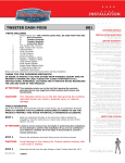
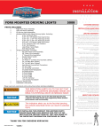
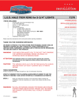
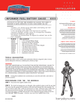
INSTALLATION
FAIRING SPEARS with L.E.D. ACCENT LIGHT/GL 1800
PARTS INCLUDED
1
1
1
Left Fairing Spear with L.E.D. Accent
Right Fairing Spear with L.E.D. Accent
Hardware Kit Containing
2
Alcohol Pads
2
Y-Adapter Plugs—5-1/4” Long
1
Installation Instructions
Please read and understand entire instructions before starting installation.
THANK YOU FOR CHOOSING KϋRYAKYN!
IN ORDER TO PROTECT YOU AND OTHERS FROM POSSIBLE INJURY AND/OR
PROPERTY DAMAGE OR LOSS, PLEASE PAY CLOSE ATTENTION TO ALL
INSTRUCTIONS, WARNINGS, CAUTIONS AND ATTENTION NOTES REGARDING
THE USE AND CARE OF THIS PRODUCT.
WARNING!
THIS INDICATION ALERTS YOU TO THE FACT THAT IGNORING
THE CONTENTS DESCRIBED HEREIN CAN RESULT IN
POTENTIAL DEATH OR SERIOUS INJURY.
ATTENTION! This indication alerts you to the fact that ignoring the contents
described herein may negatively affect product performance and
functionality.
CAUTION!
This indication alerts you to the fact that ignoring the contents
described herein can result in potential injury or material
damage.
TOOLS SUGGESTED
Phillips screwdriver, Center Punch, Set of Metric Hex Wrenches,
STRICTLY OBSERVE THE FOLLOWING GUIDELINES IN ORDER TO USE THE
PRODUCT PROPERLY AND AVOID POTENTIALLY DANGEROUS ACCIDENTS.
STEP 1
Read and understand all steps in the instructions before starting the
installation. Park the motorcycle on a hard, level surface and turn off the
ignition.
NOTE: ‘06 to ‘10 models, that do not have existing Kuryakyn front accent
lighting, require P/N 7300, Adapter Plug, (purchased separately) for
Plug and Play wiring.
ATTENTION!
A factory service manual may be helpful in performing this installation.
Do not attempt to perform this installation if you are not confident in
your ability to complete all steps in the procedure; consult a trained
technician.
STEP 2
Remove any grease or debris from both sides of the outer fairing with soapy
water and a clean rag; rinse and allow the area to dry completely PIC 1. Clean
the area with the included alcohol cleaning pad to remove any residue; allow
the area to dry completely.
7337-21GL-0711
-cont.-
7337
CUSTOMER SERVICE
877.370.3604 (toll free)
INSTALLATION QUESTIONS
[email protected]
or call 715.247.2983
LIMITED WARRANTY
Küryakyn warrants that any Küryakyn products
sold hereunder, shall be free of defects in
materials and workmanship for a period of one
(1) year from the date of purchase by the
consumer excepting the following provisions:
● Küryakyn shall have no obligation in the event
the customer is unable to provide a receipt
showing the date the customer purchased the
product(s).
●The product must be properly installed,
maintained and operated under
normal conditions.
●Küryakyn makes no warranty, expressed or
implied, with respect to any gold plated
products.
●Küryakyn shall not be liable for any
consequential and incidental damages, including
labor and paint, resulting from failure of a
Küryakyn product, failure to deliver, delay in
delivery, delivery in nonconforming condition, or
for any breech of contract or duty between
Küryakyn and a customer.
●Küryakyn products are often intended for use in
specific applications. Küryakyn makes no
warranty if a Küryakyn product is used in
applications other than intended.
●Küryakyn electrical products are warranted for
one (1) year from the date of purchase by the
consumer. L.E.D.’S contained in components of
Küryakyn products will be warranted for defects
in materials and workmanship for 3 years from
the date of purchase where as all other
components shall be warranted for one(1) year.
This includes, but is not limited to; control
modules, wiring, chrome & other components.
●Küryakyn makes no warranty of any kind in
regard to other manufacturer¹s products
distributed by Küryakyn. Küryakyn will pass on
all warranties made by the manufacturer and
where possible, will expedite the claim on behalf
of the customer, but ultimately, responsibility for
disposition of the warranty claim lies
with the manufacturer.
ABOUT OUR CATALOG
For purchasing Küryakyn® products, you
can receive a complete catalog free of charge.
Send the Proof-of-Purchase below with
your address to: Küryakyn, P.O. Box 339,
Somerset, WI 54025.
Please indicate either Accessories Catalog for
Harley-Davidson® or GL & Metric Cruisers.
Be sure to ask your local dealer about other
Küryakyn® products, the motorcycle parts and
accessories designed for riders by riders.
©2005 Küryakyn USA® All Rights
reserved.
ATTENTION! Thoroughly clean the area of grease, oil, dirt, or other debris to ensure
proper adhesion. Küryakyn WILL NOT warranty any parts lost due to
improper installation.
STEP 3
PIC 1
Test fit the left Fairing Spear to the fairing. They will install just above the body
line groove, not in the channel. Make any reference marks with a non-permanent
marker or masking tape. PIC 1 as a starting point, the rear of the L.E.D. Fairing
Spear will be about 1-1/4” above the deepest part of the body groove.
ATTENTION! The adhesive may not correctly bond if applied at temperatures less than
CLEAN THIS AREA ON BOTH SIDES
50°F. Do not attempt this installation in temperatures less than 50°F.
STEP 4
PIC 2
Rub the backing on the adhesive strip to activate the adhesive before applying.
Remove the adhesive backing. Press the Fairing Spear to the left side of the fairing
into place for 1 minute to ensure proper adhesion. Full bond strength will occur
within 24 hours. PIC 1 Repeat for right side.
NOTE: If the bike be will ridden before the Fairing Spears have been installed for
24 hours, Kuryakyn recommends that you use masking tape over the
Fairing Spears to ensure proper adhesion.
STEP 5
STEP 6
Locate the rubber boot at the base of each mirror. Carefully peel this boot back
away from the fairing to expose the wire connections. Pay attention to how the
boot joins with the fairing; this will aid in replacing the boot in its proper position
during reassembly. PIC 3
PIC 3
Carefully remove the trim molding from each side as shown in PIC 4. The upper
edge has a tab that fits into a slot under the fairing. PIC 5 You may find it helpful
to start removing the trim at the bottom and work your way to the upper edge.
PEEL MIRROR BOOT BACK
STEP 7
Remove the side compartments. Use a center punch to depress the locking
mechanism in each of the plastic fasteners. PIC 6 The right side compartment
(sitting on the bike) needs to be opened with a key, then remove two Phillips head
screws and two of the locking plastic fasteners.
STEP 8
Thread the connector end of the wire harness under the front of the fairing, above
the inside fairing vent, to behind the fairing up to the mirror joint, a piece of stiff
wire or a straightened coat hanger
PIC 5
with the connector of the wire
harness taped to it, may ease
threading this through the fairing.
PIC 7 and PIC 8
PIC 4
TAB FITS INTO SLOT
ATTENTION! Secure all wiring away from any
moving parts, pinch points or
extreme heat. Küryakyn WILL
NOT issue a warranty on any
electrical component that fails
due to pinched, crimped, broken,
abraded, melted or frayed wires.
START AT THE
BOTTOM AND WORK
TO THE TOP
PAGE
2
-cont.-
L.E.D. FAIRING SPEARS
INSTALLATION
ATTENTION! Küryakyn recommends the use of dielectric grease on electrical connections.
PIC 6
STEP 9
For ’06–up models with P/N 7300 adapter: Apply dielectric grease to all the
electrical connections. Connect the adapter to the wire harness, then to the turn
signal harness.
For all other models: Apply dielectric grease to all the electrical connections.
Connect the “Y” connector to the wire harness, then to the turn signal harness.
REMOVE THESE
FOUR FASTENERS
NOTE: If you have already installed additional Kuryakyn accessory lights on the
front of the bike and you do not have an extra plug in you may use
Kuryakyn P/N 7302, Multi-Plug and Play Connector, with the existing
Kuryakyn wire adapter for additional plug-ins in place of the included wire
adapter.
STEP 10
With the motorcycle running, test the Fairing Light, running lights, and turn signal
for proper operation.
WARNING!
ENSURE PROPER RUNNING LIGHT AND TURN SIGNAL OPERATION
BEFORE RIDING THE MOTORCYCLE. VISIBILITY IS A MAJOR
CONCERN FOR MOTORCYCLISTS. RUNNING LIGHT OR TURN
SIGNAL MALFUNCTION COULD RESULT IN DEATH OR SERIOUS
INJURY.
STEP 11
Tuck any excess wire harness behind the mirror joint. Roll the rubber boot back
into position against the base of each mirror.
PIC 7
THREAD WIRES
THROUGH HERE
PIC 8
ATTENTION! Secure all wiring away from any moving parts, pinch points or extreme
heat. Küryakyn WILL NOT issue a warranty on any electrical component
that fails due to pinched, crimped, broken, abraded, melted or frayed
wires.
STEP 12
Replace each side compartment. To engage the plastic fasteners, first be sure the
locking mechanism is in the raised position as shown in PIC 11. Place a fastener in
each hole then press straight down on the locking mechanism to engage.
STEP 13
Replace each trim molding. Fit the lip at the top of the molding into the slot under
the fairing then carefully snap the length of the molding into place.
PIC 9
PIC 10
PIC 11
THREAD WIRE
THROUGH POCKET
LIKE THIS
BE SURE TO RAISE
LOCKING MECHANISM
WIRE EXITS HERE
Ride On!
PAGE
3
L.E.D. FAIRING SPEARS
INSTALLATION