1
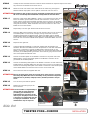
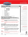
INSTALLATION
TWEETER DASH PODS
PARTS INCLUDED
1
Kicker Tweeter Set—ONLY PARTS LISTED WILL BE USED FROM THIS BOX
4
Butt Connectors
2
Tweeter Housings
2
Tweeter Speakers
2
Cross-Over Boxes
1
Left Tweeter Pod—Chrome
1
Right Tweeter Pod—Chrome
2
Indexing Plates
4
#8 Hi Lo Screws
6
#8 Flat Washers
2
#8-32 Hex Nuts
2
Positive Y Adapters—White
2
Negative Y Adapters—Black
2
Large Female Spades
2
Small Female Spades
4
Double Sided Adhesive Pads
6
4” Black Nylon Cable Ties
1
Installation Instructions
Please read and understand entire instructions before starting installation.
THANK YOU FOR CHOOSING KϋRYAKYN!
IN ORDER TO PROTECT YOU AND OTHERS FROM POSSIBLE INJURY AND/OR
PROPERTY DAMAGE OR LOSS, PLEASE PAY CLOSE ATTENTION TO ALL
INSTRUCTIONS, WARNINGS, CAUTIONS AND ATTENTION NOTES REGARDING
THE USE AND CARE OF THIS PRODUCT.
ATTENTION! This indication alerts you to the fact that ignoring the contents
described herein may negatively affect product performance and
functionality.
CAUTION!
This indication alerts you to the fact that ignoring the contents
described herein can result in potential injury or material
damage.
TOOLS SUGGESTED
Set of Torx Wrenches, Set of Drill Bits and Drill, Center Punch, Set of Combination Wrenches
STRICTLY OBSERVE THE FOLLOWING GUIDELINES IN ORDER TO USE THE
PRODUCT PROPERLY AND AVOID POTENTIALLY DANGEROUS ACCIDENTS.
STEP 1
Read and understand all steps in the instructions before starting the
installation. Park the motorcycle on a hard, level surface and turn off the
ignition. Let cool.
ATTENTION! A factory service manual may be helpful in performing this installation.
Do not attempt to perform this installation if you are not confident in
your ability to complete all of the steps in the procedure; consult a
trained technician.
STEP 2
Remove the windscreen and outer fairing as per the service manual.
CAUTION!
Avoid damage to the motorcycle. Protect painted surfaces with
a soft cloth or blanket.
STEP 3
Determine the left from the right (sitting on bike) Tweeter Dash Pod. PIC 1
881-22HD-1211
-cont.-
881
CUSTOMER SERVICE
877.370.3604 (toll free)
INSTALLATION QUESTIONS
[email protected]
or call 715.247.2983
LIMITED WARRANTY
Küryakyn warrants that any Küryakyn products
sold hereunder, shall be free of defects in
materials and workmanship for a period of one
(1) year from the date of purchase by the
consumer excepting the following provisions:
● Küryakyn shall have no obligation in the event
the customer is unable to provide a receipt
showing the date the customer purchased the
product(s).
●The product must be properly installed,
maintained and operated under
normal conditions.
●Küryakyn makes no warranty, expressed or
implied, with respect to any gold plated
products.
●Küryakyn shall not be liable for any
consequential and incidental damages, including
labor and paint, resulting from failure of a
Küryakyn product, failure to deliver, delay in
delivery, delivery in nonconforming condition, or
for any breech of contract or duty between
Küryakyn and a customer.
●Küryakyn products are often intended for use in
specific applications. Küryakyn makes no
warranty if a Küryakyn product is used in
applications other than intended.
●Küryakyn electrical products are warranted for
one (1) year from the date of purchase by the
consumer. L.E.D.’S contained in components of
Küryakyn products will be warranted for defects
in materials and workmanship for 3 years from
the date of purchase where as all other
components shall be warranted for one(1) year.
This includes, but is not limited to; control
modules, wiring, chrome & other components.
●Küryakyn makes no warranty of any kind in
regard to other manufacturer¹s products
distributed by Küryakyn. Küryakyn will pass on
all warranties made by the manufacturer and
where possible, will expedite the claim on behalf
of the customer, but ultimately, responsibility for
disposition of the warranty claim lies
with the manufacturer.
ABOUT OUR CATALOG
For purchasing Küryakyn® products, you
can receive a complete catalog free of charge.
Send the Proof-of-Purchase below with
your address to: Küryakyn, P.O. Box 339,
Somerset, WI 54025.
Please indicate either Accessories Catalog for
Harley-Davidson® or GL & Metric Cruisers.
Be sure to ask your local dealer about other
Küryakyn® products, the motorcycle parts and
accessories designed for riders by riders.
©2005 Küryakyn USA® All Rights reserved.
STEP 4
Place the left Tweeter Dash Pod on the inner fairing and mark the mounting holes and the wire
harness hole with a center punch. PIC 2 Remove the Tweeter Dash Pod from the inner fairing.
STEP 5
Using a 3/16” drill bit, slowly drill the top and bottom holes through the inner
fairing. Using a 1/4” drill bit, drill the center hole through the inner fairing.
PIC 1
LEFT
RIGHT
NOTE: Drill slowly, the inner fairing is soft and you DO NOT want the chuck of the
drill to run into the inner fairing. Ensure the center hole is NOT drilled
through the horizontal rib on the inner fairing. PIC 8 and PIC9
CAUTION!
MEASURE TWICE – DRILL ONCE. Double check all reference
marks made on the inner fairing BEFORE drilling. Kuryakyn will
not be responsible for incidental or consequential damages
resulting from this installation.
STEP 6
Locate the Tweeter speakers and housings from the Kicker box, and the indexing
plates, 2-#8 flat washers and 2-#8 hex nuts, from the Pod hardware kit.
STEP 7
Insert one of the indexing plates into each of the Tweeter Housings. The stud on
the indexing plate fits through either hole in the housing and extends out of the
back of the housing. PIC 3 and PIC 4
STEP 8
Insert the wire harness of the Tweeter through the center hole in the housing and
thread the Tweeter into the housing. Tighten until the Tweeter is flush with the
housing. PIC 5
PIC 2
MARK AND
DRILL THESE
THREE HOLES
PIC 3
NOTE: Take your time lining up the threads between the housing and the
Tweeter, they are fine threads and will cross thread easily.
STEP 10
Insert the wire harness from the Tweeter through the center hole in the left
Speaker Pod. The stud should extend out through the semi-circle slot. PIC 6
STEP 11
Using one of the #8 flat washers and one of the #8 hex nuts, attach the Tweeter
to the speaker Pod. Leave loose, turn the Speaker Pod over and make sure the
Kicker emblem is centered in the Pod. PIC 7 You may gently turn the Tweeter to
center this emblem. After centering the emblem, tighten the #8 hex nut securely.
MAKE SURE
STUD EXITS
THROUGH
HOLE
PIC 4
NOTE: If you cannot get the Tweeter to turn enough to center the emblem,
disassemble the Tweeter from the housing, remove the Indexing Plate,
turn the Plate 180 degrees and insert the stud on the Indexing Plate
through the other hole in the housing.
STEP 12
Insert the wire harness from the Speaker Pod through the center hole from Step 5.
(If the hole for the wire harness from the Speaker Pod is above the rib in the inner
fairing, the rib will need to be notched, using a file or cutting tool, so it does not
get pinched when the outer fairing is installed. PIC 8) From the inside of the inner
PIC 5
fairing, attach the Speaker Pod using one of the #8 flat washers and one of the
#8 hi-low screws in the top and bottom holes from Step 5. Tighten Securely. PIC 9
SPEAKER
FLUSH WITH
HOUSING
ATTENTION! It is the installer’s responsibility to ensure that all of the fasteners
(including pre-assembled) are tightened before operation of the
motorcycle. Küryakyn will not issue a warranty on components lost due to
improper installation. Periodic maintenance may be required.
STEP 13
Repeat Step 4 through Step 12 for the right side.
STEP 14
Thoroughly clean the underside of the radio with an ammonia based cleaner such
as window cleaner.
ATTENTION! Ensure the area of installation is free of grease, oil, dirt or other debris to
ensure proper adhesion. Küryakyn WILL NOT issue a warranty on any parts lost due to
improper installation.
PAGE
2
-cont.-
TWEETER PODS—CHROME
INSTALLATION
STEP15
Unwrap the wire harnesses from the crossover boxes and mark the input and output wires with a
tag. The boxes are marked on the ends. PIC 10
STEP 16
Attach the cross-over boxes to the under side of the radio using the supplied
adhesive backed tape pads. Use two pads on each cross-over box. PIC 11
PIC 6
ROUTE WIRES HERE
ATTENTION! The adhesive will not bond correctly if applied at temperatures less than
50°F. Do not attempt this installation in temperatures less than 50°F.
STEP 17
Route the output wires (END LABELED — KS25 +) from the Cross-over box on the
left to the Tweeter pod mounted on the left side of the bike. Cut the wires to
length, leaving a little slack and attach the GRAY wire from the box to the GRAY
wire from the Tweeter using one of the butt connectors supplied in the Kicker box.
Using a Butt connector, attach the BLACK wire from the Cross-over box to the
BLACK wire from the Tweeter.
STEP18
Repeat Step 17 for the right Tweeter Pod and Cross-over box.
STEP 19
Route the INPUT wires marked in Step 15 from the left Cross-over box to the left
front OEM speaker. Cut the wires to length, leaving a little slack. From the
hardware supplied with the Speaker Pods, locate one SMALL and one LARGE
Female spade. Attach the SMALL female spade to the GRAY INPUT wire from the
left Cross-over box and the LARGE female spades to the BLACK INPUT wire from
the box.
STEP 20
Repeat for the right side.
STEP 21
Locate the WHITE and BLACK Y Connectors supplied with the Speaker Pod
hardware. Disconnect the OEM wires from the speakers on each side and attach
them to the Y Connectors. Connect the Male spade (with two wires) on the
WHITE Y Connector to the OEM speaker power wire. Connect the Male spade (with
two wires) to the OEM speaker ground wire. These will only plug into the correct
wire as the spades are different sizes.
STEP 22
Connect the Female spade on the WHITE Y Connector to the power side of the
OEM speakers. Connect the Female spade on the BLACK Y Connector to the
ground side of the OEM speakers.
STEP 23
Connect the Remaining Male spade on the WHITE Y Connector on each side to the
Female spade on the GRAY INPUT wire from the Cross-over box on the same side.
Connect the remaining Male spade on the BLACK Y Connector to the Female spade
on the BLACK INPUT wire from the Cross-over box on the same side.
STEP 24
Secure the wires with the supplied cable ties.
heat. Küryakyn WILL NOT issue a warranty on any electrical component
that fails due to pinched, crimped, broken, abraded, melted or frayed
wires.
Turn on the key and test the system.
STEP 26
Replace the outer fairing as per the
service manual.
PIC 7
CENTER EMBLEM
PIC 8
ATTENTION! Secure all wiring away from any moving parts, pinch points or extreme
STEP 25
STUD THROUGH
SLOT SECURE
WITH #8 FLATWASHER AND
#8 HEX NUT
IF WIRE IS
ABOVE RIB,
NOTCH THE
RIB FOR
CLEARANCE
ENSURE HOLE IS NOT DRILLED
THROUGH RIB
PIC 9
#8 FLAT
WASHERS
AND HI-LO
SCREWS
PIC 10
WIRES FROM
OUTPUT TO
TWEETERS
PIC 11
ATTENTION! It is the installer’s responsibility to
WIRES FROM
INPUT TO OEM
SPEAKERS
ensure that all of the fasteners
(including pre-assembled) are
tightened before operation of the
motorcycle. Küryakyn will not issue
a warranty on components lost due
to improper installation. Periodic
maintenance may be required.
Ride On!
ATTACH CROSS-OVER BOXES
UNDER RADIO
TWEETER PODS—CHROME
PAGE
3
INSTALLATION