1
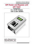
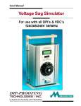
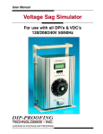
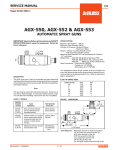
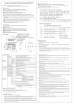
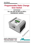
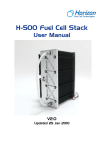
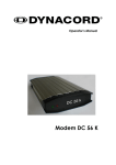
Installation & Service Manual
Voltage-Dip Compensators
For VDC L4T/L6T & S4T/S6T series
Models
120V / 208V / 220V / 230V 50/60Hz
DIP-PROOFING
TECHNOLOGIES
INC.
LEADERS IN VOLTAGE-DIP PROOFING
Installation & Service Manual
Contents
Introduction .............................................................................. 3
Theory of operation ................................................................. 3
Specifications .......................................................................... 5
VDC support for the SEMI F47 standard ................................. 7
Installation Guide ..................................................................... 9
Power Wiring............................................................................ 9
Indicator error codes .............................................................. 11
Adjustments ........................................................................... 11
Compensator Run Time......................................................... 11
I2t controlled run time curves ................................................ 12
Fault Diagnosis Chart ............................................................ 13
Mechanical Construction ....................................................... 16
Dimension Table .................................................................... 16
Mechanical Outline ................................................................ 17
Accessories ........................................................................... 18
Voltage Sag Simulator ........................................................... 19
Notice
IMPORTANT SAFETY INSTRUCTIONS.
SAVE THESE INSTRUCTIONS!
This manual contains important instructions that should be followed during
installation and adjustment of VDC series Voltage Dip Compensators.
Page 2
VDC L4T/L6T & VDC S4T/S6T Series - Firmware ver 1.4 & up
Installation & Service Manual
Introduction
The reliability of electrical power to industry is in general very high, nevertheless,
voltage sags or dips do occur. These instabilities are caused by short circuits, lightning
strikes on overhead power lines and heavy load switching. The duration of such faults is
generally shorter than one second. Power Quality data shows that voltage sags with a
maximum depth of around 50% constitute 92% of all events.
Most plant can ride through such voltage dips by virtue of their mechanical
and electrical inertia. However, this is not the case with electrically held-in contactors and
relays that control the machinery. Contactors typically drop out from 5ms to 20ms after
power is removed. Each short voltage dip now becomes a power failure and the plant must
be restarted. This can be complicated, time-consuming and costly.
DIP-PROOFING TECHNOLOGIES’ Voltage Dip Compensators are designed to maintain the switchgear control voltage during voltage sags, effectively keeping
the plant connected. The stored electrical and magnetic energy is allowed to flow,
supporting the mechanical inertia of the machinery. When the power is restored after a
short voltage dip, the plant is still running at near synchronous speed, the inrush currents
will be small and the stress to the system minimal. The VDC provides an economic
solution for users who need their equipment to comply with the Semi F47 standard for
voltage sag immunity.
Historically, this problem has been addressed by using DC contactors,
latched contactors and intelligent controls such as PLC’s. These systems are complex
and expensive and do not provide a solution for equipment already in existence. The
current approach to this problem has been to employ intelligent control systems which
provide a curative solution. In contrast, the Voltage Dip Compensator, provides a
preventative solution.
Theory of operation
The VOLTAGE-DIP COMPENSATOR is designed to be maintenance free and
highly reliable. It consists of 5/7 static switches , a sag compensation transformer and the
controls. The Voltage Dip Compensator block diagram is shown in Fig 1 below.
1
3
Static
Switch - 1
Static
Switch - 2
Compensation
Transformer
Static
Switch - 3
Supply in
Controls
Static
Switch - 4
To Load
Static
Switch - 5
Static
Switch - 6
Static
Switch - 7
6 Tap
models only.
2
Fig 1
Compensator Block Diagram
VDC L4T/L6T & VDC S4T/S6T Series - Firmware ver 1.4 & up
Page 3
Installation & Service Manual
Volts
The STATIC SWITCHES are robust and can withstand large current surges. They
are ideally suited for contactor operation where high peak currents of short duration occur
during energizing.
V in (Sag duration 42ms)
V out
Supply
sags
300
Supply
recovers
200
100
0
-100
-200
-300
Compensator Running
0
10
20
30
40
50
60
70
80
90
100
Time ms
Fig 2
Compensator output waveform.
During stand-by operation, static switch1 supplies power directly to the load,static
switches 2 to 5 are switched off and the compensation transformer carries no load. The
supply voltage is constantly monitored for deviations; should there be a deviation from
Vnom which is greater than ±10%, static switch 1 is switched off and static switch 2 is
activated. Depending on the sag depth the controls will operate static switches 2 to 5/7
to maintain the compensator output voltage within ±10% of the nominal supply voltage.The
switch-over is accomplished in 350µs. A 3.15 second timer, adjustable in increments of
50ms , starts timing the compensator out. Should the input voltage recover within the set
time, static switches 2 to 5/7 will be deactivated and static switch 1 will be switched on and
the load is reconnected to the supply. If the input voltage does not recover within the set
time the load is switched back to the supply regardless of the voltage level. If I2t control
is enabled then the run time will be dynamically optimized to the longest time that load
conditions will allow.
The VDC employs tap switch fuses to prevent catastrophic damage to the unit in
the event of a tap switch failure. If a tap switch should fail the fuse will open. A VDC with
a failed tap switch will continue to function normally and will attempt to serve any sags that
occur. However if sag conditions require activation of the failed tap then the load will be
dropped because there is no output from that tap.
Page 4
VDC L4T/L6T & VDC S4T/S6T Series - Firmware ver 1.4 & up
Installation & Service Manual
Specifications
VDC L4T/L6T & S4T/S6T series 120V models
VDC L6T3K120
VDC L4T3K120
VDC S6T1K120
VDC S4T1K120
120V MODELS
AC INPUT SUPPLY
120V
Single phase supply voltage 50/60Hz:
+10%
Maximum input voltage:
Minimum input voltage:
-50%
-64%
-50%
-64%
8.5A
Full load current (A RMS):
8.5A
24A
24A
550A
Maximum surge current for 3 seconds duration:
AC OUTPUT
120V
Nominal output voltage:
± 10%
Voltage fluctuations over full operating range:
8.5A
24A
24A
Nominal load current (A):
8.5A
cos ⌽ from 1 to 0
Power factor range:
Sinusoidal
Wave shape:
Nominal load (VA):
1000
1000
3000
3000
Maximum up-time (sec):
3.15s
Timer control:
See Figs 9 & 10 p12
I2t control:
12A
Overload current limit (A RMS):
12A
35A
35A
30A
Short circut curremt limit (A RMS):
30A
75A
75A
TIMER
0.05 to 3.15s
Range:
0.05s steps
Setting:
INDICATORS
green LED
System OK:
red LED
Compensator running:
TEMPERATURE
45°C (113°F)
Maximum ambient working temperature:
CUBICLE
Extruded Aluminum
Construction:
Height (mm) (Dim. L3 on p17):
280
305
273
273
Height (in) (Dim. L3 on p17):
11.02
12.07
10.75
10.75
150 (5.90)
311 (12.24)
Width mm (in):
110
(4.33)
162 (6.38)
Depth mm (in):
Mass (kg):
5.0
5.0
9.0
9.0
Mass (lbs):
11.0
11.0
19.8
19.8
CONNECTION
2mm 2
5mm 2
Cable, Copper panel wire; size mm 2:
14 AWG
10 AWG
Cable, Copper panel wire; size AWG:
1.76Nm (15.6lb-n)
Screw terminal torque Nm (lb-in):
LISTINGS
Listing pending.
Underwriters Laboratories Inc:
STANDARDS SUPPORTED
Semiconductor processing equipment voltage sag immunity.
SEMI F47:
The VDC family is designed for applications that must meet the SEMI F47 Voltage Sag Immunity Standard for Semiconductor Processing Equipment and where size and cost are critical
factors.
VDC L4T/L6T & VDC S4T/S6T Series - Firmware ver 1.4 & up
Page 5
Installation & Service Manual
Specifications
VDC L4T/L6T & S4T/S6T series 208V / 220V / 230V models
AC INPUT SUPPLY
Single phase supply voltage 50/60Hz:
Maximum input voltage:
Minimum input voltage:
Full load current (A RMS):
Maximum surge current for 3 cycles duration:
AC OUTPUT
Nominal output voltage (V):
Voltage fluctuations over full operating range:
Nominal load current (A):
Power factor range:
Wave shape:
Nominal load (VA):
Maximum up-time (sec):
Timer control:
I2t control:
Overload current limit (A RMS):
Short circut curremt limit (A RMS):
TIMER
Range:
Setting:
INDICATORS
System OK:
Compensator running:
TEMPERATURE
Maximum ambient working temperature:
CUBICLE
Construction:
Height (mm) (Dim. L3 on p17):
Height (in) (Dim. L3 on p17):
Width mm (in):
Depth mm (in):
Mass (kg):
Mass (lbs):
CONNECTION
Cable, Copper panel wire; size mm 2:
Cable, Copper panel wire; size AWG:
Screw terminal torque Nm (lb-in):
LISTINGS
Underwriters Laboratories Inc:
STANDARDS SUPPORTED
SEMI F47:
208V
220V
208V
220V
VDC L6T5K230
VDC L4T5K230
VDC S6T1K230
VDC S4T1K230
VDC L6T5K220
VDC L4T5K220
VDC S6T1K220
VDC S4T1K220
VDC L6T5K208
VDC L4T5K208
VDC S6T1K208
VDC S4T1K208
208 / 220 /230V MODELS
230V
+10%
-50% -64% -50% -64% -50% -64% -50% -64% -50% -64% -50% -64%
4.8A
24A
4.6A
22.7A
4.3A
21.7A
550A
4.8A
24A
4.6A
1000
5000
1000
28A
75A
3.15s
See Figs 9 & 10 p12
12A
28A
12A
35A
75A
35A
12A
35A
230V
± 10%
22.7A
4.3A
cos ⌽ from 1 to 0
Sinusoidal
5000
1000
21.7A
5000
28A
75A
0.05 to 3.15s
0.05s steps
green LED
red LED
45°C (113°F)
293
280 304
11.02 11.97 11.54
150 (5.90) 311 (12.24)
110 (4.33) 162 (6.38)
9.0
5.0
11.0
19.8
2mm 2
14AWG
5mm 2
10AWG
Extruded Aluminum
293
293
280 304
280 304
11.02 11.97 11.54
11.02 11.97 11.54
150 (5.90) 311 (12.24) 150 (5.90) 311 (12.24)
110 (4.33) 162 (6.38) 110 (4.33) 162 (6.38)
5.0
9.0
5.0
9.0
11.0
19.8
11.0
19.8
2mm 2
5mm 2
2mm 2
14AWG
10AWG
14AWG
1.76Nm (15.6lb-in)
5mm 2
10AWG
Listing pending.
Semiconductor processing equipment voltage sag immunity.
The VDC S6T & L6T series should be used for critical applications where support down to
37% of nominal supply voltage is needed.
Page 6
VDC L4T/L6T & VDC S4T/S6T Series - Firmware ver 1.4 & up
Installation & Service Manual
VDC support for the SEMI F47 standard
100
0
90
10
80
20
70
Required equipment voltage
sag ride through capability.
This is the equipment "no fault"
operation area.
60
50
40
30
30
40
50
60
F47 Specification
0.05 to 1 sec
70
20
80
10
90
0
0.01 0.02
0.1
Sag depth % Vsupply
Vsupply %
This standard was drafted by the Semiconductor Industry to specify Voltage Sag
Immunity requirements for semiconductor processing equipment. The profile for the F47
standard is shown in Fig 3.
1
10
100
Sag duration sec
100
Fig 3
SEMI F47 Standard.
The blue zone represents the operation area where no equipment faults must
occur due to voltage sags on the supply. The “no fault” window is from 50ms to 1 second
with variable depth sag to a maximum of 50% of the nominal supply voltage.
The VDC family is designed for applications that must meet the SEMI F47 Voltage
Sag Immunity Standard for Semiconductor Processing Equipment and where size and
cost are critical factors.
Vsupply %
0
90%
90
78%
%
80
70
67%
58%
60
40
30
20
10
0
0.01 0.02
0.1
60
5.9s 8.6s12.5s
11s 15s 22s 32s 46s 67s
VDC support provides voltage sag
immunity and extends the "no fault"
equipment operation area.
1
30
50
For 120V models - 9.6A 2.1s 3.0s 4.1s
For 230V models - 4.3A
F47 Specification
0.05 to 1 sec
20
40
50%
6 tap models o
only 43%
6 tap models only 36%
50
10
Sag depth % Vsupply
100
10
100
Sag duration sec
70
80
90
100
Fig 4
VDC extended support for the SEMI F47 Standard. Times shown are for the VDC S4T/S6T series with Iload = 9.6A for 120V models, Iload = 4.3A for
230V models & duty cycle 1 maximum length event every 20 minutes.
The green area in Fig 4 shows the extended support provided by the VDC S4T/
6T series. Support times are shown in green for 120V models at a load current of 9.6 amps
and in red for 230 models at a load current of 4.3 amps.The “no fault” window is extended
VDC L4T/L6T & VDC S4T/S6T Series - Firmware ver 1.4 & up
Page 7
Installation & Service Manual
from 50ms to 4.1 &12.5 seconds respectively with a maximum continuous sag depth of
50%. VDC L4T3K/5K & VDC L6T3K/5K support times are shown in Fig 5.
90
78%
80
70
30
58%
60
40
50%
20
VDC support provides voltage sag
immunity and extends the "no fault"
equipment operation area.
10
0
0.01 0.02
41.7s
F47 Specification
0.05 to 1 sec
23.8s
30
36%
7.7s
40
50
43%
2.1s
6 tap models only
6 tap models only
4.2s
50
0.1
1
10
20
67%
13.5s
Vsupply %
0
90%
10
100
Sag duration sec
Sag depth % Vsupply
100
60
70
80
90
100
Fig 5
VDC extended support for the SEMI F47 Standard. Times shown are for the VDC L4T/6T 3K/5K series with Iload = 24A &
duty cycle 1 maximum length event every 7 minutes.
100
0
90
10
80
20
70
30
DPI support provides
voltage sag and supply
interruption immunity.
The "no fault" equipment
operation area is extended
to protect against
momentary interruptions.
60
50
40
30
F47 Specification
0.05 to 1 sec
20
10
0
0.01 0.02
40
50
Sag depth % Vsupply
Vsupply %
The VDC S6T & L6T series should be used for critical applications where support
down to 37% of nominal supply voltage is needed. The Fig 5 shows the extended support
area. The “no fault” window is extended from 50ms to 2.1 seconds with a maximum
continuous sag depth of 63%.
60
70
80
90
0.1
1
10
100
Sag duration sec
100
Fig 6
DPI support for the SEMI F47 Standard.
For applications that require protection against momentary interruptions and sags
refer to our Voltage Dip Proofing Inverter (DPI) product line for a simple cost effective
solution that is easy to intergate into OEM products or retrofit to existing equipment. The
DPI support profile is shown together with the F47 curve in Fig 6. It can be seen that the
DPI provides complete protection for all sag depths and interruptions from 0 to 3 seconds.
Page 8
VDC L4T/L6T & VDC S4T/S6T Series - Firmware ver 1.4 & up
Installation & Service Manual
Installation Guide
1.
Remove the unit from its packing
2.
Place the unit horizontally on a bench and visually check for any
mechanical damage. Ensure that all the casing screws are tight then
shake the unit to check that there is nothing loose internally.
Note : Please inform your shipping agent if any damage has occurred
during transit : the damaged unit(s) and all packing material should be
kept in case the insurers wish to inspect the damage.
3.
Check that compensator voltage is the same as the system control voltage.
Refer to the rating label on the unit end plate.
WARNING: Never connect a 120V unit to a 208V or 230V supply!
4.
Decide on the location where the unit is to be installed, this will probably
be inside a switch gear panel.
5.
Mount the unit vertically using M6 bolts.
6.
Connect unit as shown in Fig 7 using 2mm2 (14AWG), VDC S series & 5mm2
(10AWG), VDC L series copper panel wire.
7.
Apply terminal screw tightening torque of 0.6 - 0.8Nm (5.2 - 7 lb-in), VDC S series
& 1.5 - 1.8Nm (13 - 16 lb-in) VDC L series.
8.
This device does not have a disconnect switch. If such a switch is required it
must be provided by others.
Power Wiring
Connect Line In (Supply)
to
Terminal 1
Connect Common Line in
to
Terminal 2
Connect Common Line out
to
Terminal 3
Connect Line Out (Load)
to
Terminal 4
Connect the ground screw(s) to the panel ground point.
1
2*
3*
4
Ground in
Ground out
Line in
Line out
(Load)
(Supply)
Common line in
*Note: 2 & 3 linked internally.
Common line out
Fig 7
Power Wiring Diagram
VDC L4T/L6T & VDC S4T/S6T Series - Firmware ver 1.4 & up
Page 9
Installation & Service Manual
9.
Once the unit has been mounted and the external wiring completed, power
can be applied.Turn on the power to the unit. The green LED indicator
"System OK" will come on after approximately one second and the unit is
fully operational.
10.
In applications which require no break maintenance, a bypass switch
must be installed. Order the appropriate Bypass Switch (see p17) which
should be connected as shown in Fig 8.
DIP-PROOFING
TECHNOLOGIES
System
OK
INC.
Compensator
Running
Voltage Dip Compensator
VDC
1 2 3 4
Ground
Ground
To DPI
or VDC
1
2
3
4
out
in
Common Line
Line in
Line out
DPI
Bypass
Housed
Bypass
Switch
Common Line
out
in
Line in
To
Supply
1
2
3
Line out
4
Line In
Line Out
(Supply Vnom)
(Load)
Common line in
Common line out
Fig 8
Housed Bypass Switch Connection Diagram
Functional Description of the Indicators
System OK : Green LED indicator
When the green LED is ON the system is fully functional; the unit self test
& initialization routine has been run successfully.
Compensator Running : Red LED indicator
The red LED is on when the compensator is running during a voltage dip.
Page 10
VDC L4T/L6T & VDC S4T/S6T Series - Firmware ver 1.4 & up
Installation & Service Manual
Indicator error codes
Flashes
Indicator
Condition
1
2
Profile
✓
System OK
Green
✓
Star t up Test .
System OK
Green
Compensator
running
Red
Event not fully suppor ted. Resets after 24 hours.
Supply check, AC input low.
✓
Load current check, overload.
Test and Maintenance
There are no user serviceable parts inside the unit, if faulty return to factory or local
agent for repairs.
Adjustments
Adjustment points are marked on the control card and can be reached by
removing the front cover of the VDC; see Mechanical Construction on page 15.
Compensator Run Time
Timer controlled Run Time - SW1 (see Fig.11 page 13)
This switch sets the running time of the compensator and can be set in 50ms steps to a
maximum of 3.15 seconds. To determine the run time which is currently set, add the
figures printed next to each switch that is in the ON position. For example, a running time
setting of 3.15 seconds requires these switch combinations: 1-on, 2-on, 3-on, 4-on, 5-on,
6-on.
I2t controlled Run Time.
Run Time is dynamically optimized to the longest that load conditions will allow.
The I2t optimized Run Time can be determined using the curves on page 12.
To enable this option set all SW1 switches to OFF.
Factory Setting : I2t control (SW1 1-6- off)
VDC L4T/L6T & VDC S4T/S6T Series - Firmware ver 1.4 & up
Page 11
Installation & Service Manual
I2t controlled run time curves
Use the curves below (Fig 9 for “S” series & Fig 10 for “L” series) to determine the
I t controlled run times for a specific load current and sag depth. Note that the two left most
curves are for six tap models only.
2
10.00
Time - 78%
Time - 67%
Time - 58%
Time - 50%
Time - 43%
Time - 36%
9.00
Load Current (amps)
8.00
7.00
6.00
5.00
4.00
6 Tap only
6 Tap only
3.00
2.00
0.0
5.0
10.0
15.0
20.0
25.0
30.0
35.0
40.0
45.0
50.0
55.0
60.0
2
I t Up-time (seconds)
Fig 9
Maximum I t controlled Up-times for VDC S4T/S6T1K series.
Duty cycle 1 maximum length event every 20 minutes.
2
26.00
Time-78% sag
Time-58% sag
Time-43% sag
24.00
Time-67% sag
Time-50% sag
Time-36% sag
Load current (amps)
22.00
20.00
18.00
16.00
14.00
6 Tap only
12.00
0.00
5.00
6 Tap only
10.00
15.00
20.00
25.00
30.00
35.00
40.00
45.00
50.00
55.00
60.00
2
I t Up-time (sec)
Fig 10
Maximum I2t controlled Up-times for VDC L4T/S6T3K & VDC L4T/S6T5K series.
Duty cycle 1 maximum length event every 7 minutes.
Page 12
VDC L4T/L6T & VDC S4T/S6T Series - Firmware ver 1.4 & up
Installation & Service Manual
LED1
LED2
Green
Red
System OK
Running
Note 2 : VDC setting.
DSW2 is set by factory.
Do not change settings.
Note 1 : VDC setting.
To activate "I2t controlled runtime" set all
DSW1 switches to the OFF position.
DSW2
ON
DSW1
Default I2t control
1600msec
800msec
400msec
200msec
100msec
50msec
O
6
5
4
SW1
3
Off
6T
HC
On
4T
LC
AV
-
NV
-
6T - 6 tap VDC
4T - 4 tap VDC
HC - 3K/5K VDC
LC - 1K VDC
AV - Auto supply sensing on
NV - Auto supply sensing off
~ #4 Not used
2
1
Set run time
Push & release
to calibrate.
Fig 11
Control Card Indicator & Adjustment Locations
Fault Diagnosis Chart
Symptom
Probable Cause
Remedy
System OK LED (green) is off,
no voltage on output terminals.
No supply voltage on input
terminals 1 & 2.
Check supply.
System OK LED (green) is off.
Compensator Running LED
(red) flashes onc e every second.
There is no voltage on output
terminals 3 & 4.
Overload condition, load
current exceeds unit
overload rating.
Check load current, if it exceeds the Overload rating
eliminate any devices that do not need to be
suppor ted or use a larger unit.
System OK LED (green) is off,
voltage on terminals 3 & 4 no
voltage on 1 & 2.
Supply and load wires are
reversed. Terminals 1 & 4.
Powered up for > 3 seconds.
System OK LED (green) is off.
Compensator Running LED
(red) is off. There may / may not
be voltage on terminals 3 & 4.
Unit failure.
Return to local agent or manufacturer for repair.
System OK LED (green) flashes
twice every second. voltage
present on output terminals.
Low supply voltage. A
208/220/230V unit is being
used with a 120V supply.
Change unit to 120V model.
Unit failure when supply
switched on.
A 120V unit is being used on
a 208V or 220V supply.
Change unit to correct voltage model.
Note: The 120V unit will be damaged!
VDC L4T/L6T & VDC S4T/S6T Series - Firmware ver 1.4 & up
Swap supply & load wires. Supply terminal 1 and
load terminal 4.
Page 13
Page 14
4 Line out (Load)
3
2 Common line
CN3
1 Line in (Supply)
Out
In
Ground
CN4
G2 Switch
Static G1
A2
C2
TH2
R10
JP4
R8
JP3
R7
CT1
JP2
120V
JP1
220V
AC1
AC2
AC1
AC2
E1
G1
E2
G2
A1
C1
TH1
R11
R9
TX1
Z4
Z2
Z1
Z5
Z3
CN1:11
CN1:14
CN1:16
CN1:17
CN1:10
CN1:12
CN1:8
CN1:6
CN1:4
Control Card
CN1:1
CN1:7
CN1:13
CN1:3
CN1:5
CN1:9
CN1:15
G2
VSS2
E2
CTRL2 PS2
G1
VSS1
E1
CTRL1 PS1
G2
VSS2
E2
CTRL2 PS2
CN6
CN5
Tap Switch 6
Tap Switch 5
Tap Switch 4
Tap Switch 3
Tap Switch 2
G2
VSS2
E2
CTRL2 PS2
G1
VSS1
E1
CTRL1 PS1
Tap Switch 1
G1
VSS1
E1
CTRL1 PS1
Tap Switch
Drivers
VDR5
Static Switch
drivers
TAP6
CN2:
TAP5
CN2:
TAP4
CN2:2 5
TAP3
CN2:3 4
TAP2
CN2:6 1
TAP1
CN2:4
CN2:1
3
6
6 Tap models only.
F6
F5
F4
F3
F2
F1
CN2:5 2
4 tap
1
7
9
8
2
4
6 tap
Compensation
Transformer
Installation & Service Manual
Fig 12
VDC Block Wiring Diagram
VDC L4T/L6T & VDC S4T/S6T Series - Firmware ver 1.4 & up
Installation & Service Manual
Notes
VDC L4T/L6T & VDC S4T/S6T Series - Firmware ver 1.4 & up
Page 15
Installation & Service Manual
Mechanical Construction
VDC S series - The VDC case is made from extruded aluminium sections. The four parts
that make up the case are interlocked and secured by screws. To remove the front cover
unscrew four screws : the two top screws from the end plate where the terminal block is
located and the two bottom screws from the other end plate. Slide the front cover away
from the terminal block to access adjustment area.
VDC L series - The VDC case is made from extruded aluminium sections. The six parts
that make up the case are interlocked and secured by screws. To remove the front cover
unscrew three screws : one from the front cover and one each from the top and bottom
end plates.
Dimension Table
Model
VDC S4T1K120
VDC S6T1K120
VDC L4T3K120
VDC L6T3K120
VDC S4T1K208
VDC S6T1K208
VDC L4T5K208
VDC L6T5K208
VDC S4T1K220
VDC S6T1K220
VDC L4T5K220
VDC L6T5K220
VDC S4T1K230
VDC S6T1K230
VDC L4T5K230
VDC L6T5K230
Page 16
L1
177 (6.97)
200 (7.87)
L2
237 (9.33)
260 (10.24)
VDC Dimensions mm (in)
L3
L4
L5
L6
280 (11.02)
110 (4.33) 150 (5.90) 30 (1.18)
303 (11.93)
170 (6.69)
250 (9.84)
293 (11.54) 162 (6.38) 311 (12.24) 40 (1.57) 296 (11.65) 8.0 (0.31)
177 (6.97)
200 (7.87)
237 (9.33)
260 (10.24)
280 (11.02)
110 (4.33) 150 (5.90)
303 (11.93)
170 (6.69)
250 (9.84)
293 (11.54) 162 (6.38) 311 (12.24) 40 (1.57) 296 (11.65) 8.0 (0.31)
177 (6.97)
200 (7.87)
237 (9.33)
260 (10.24)
280 (11.02)
110 (4.33) 150 (5.90)
303 (11.93)
170 (6.69)
250 (9.84)
293 (11.54) 162 (6.38) 311 (12.24) 40 (1.57) 296 (11.65) 8.0 (0.31)
177 (6.97)
200 (7.87)
237 (9.33)
260 (10.24)
280 (11.02)
110 (4.33) 150 (5.90)
303 (11.93)
170 (6.69)
250 (9.84)
293 (11.54) 162 (6.38) 311 (12.24) 40 (1.57) 296 (11.65) 8.0 (0.31)
30 (1.18)
30 (1.18)
30 (1.18)
L7
D
140 (5.50) 6.0 (0.24)
140 (5.50) 6.0 (0.24)
140 (5.50) 6.0 (0.24)
140 (5.50) 6.0 (0.24)
VDC L4T/L6T & VDC S4T/S6T Series - Firmware ver 1.4 & up
Installation & Service Manual
Mechanical Outline
L7
"L" series case.
ØD
"S" series case.
Model # example
DPI52S50-23
or
VDC S4T1K230
L6
L1
L2
L3
L1*
Model # example
DPI52L3K23
or
VDC L4T5K120
L1
L2
L3
ØD
L6
L6
L7
1 2 3 4
L1*
Terminal
Cover
L4
Ground
Screws
L6
1 2 34
L5
1 2 3 4
Terminal
Cover
1 2 34
VOLTAGE DIP-PROOFING INVERTER
MODEL
VOLTS
SERIAL #
POWER
DATE MFG
HZ
L5
L4
Ground
Screws
Note 1:
Terminal cover shown dashed.
Note 2:
Terminal #1 - Line in (Supply)
Terminal #2 - Common line in
Terminal #3 - Common line out
Terminal #4 - Line out (Load)
Fig 13
Dimensions of the VDC series mm (inches)
VDC L4T/L6T & VDC S4T/S6T Series - Firmware ver 1.4 & up
Page 17
Installation & Service Manual
Accessories
Housed Bypass Switch
Description
Where no-break maintenance is required a by pass switch must be installed. It connects
the supply directly to the load, "Bypass" position, and disconnects the power terminals of
the inverter without interrupting the supply. When in "DPI" position the load is connected
to the supply via the inverter.
Specifications
MODEL
ELECTRICAL
Maximum current:
Maximum input voltage:
TEMPERATURE
Maximum working temperature:
HOUSING
Construction:
Height:
Width:
Depth:
Mass:
BPSW25A
25A
600Vac
45°C (113°F)
Extruded Aluminum
202mm (7.95in)
150mm (5.9in)
141mm (5.55in)
1kg (2.2lbs)
Mechanical outline
Note 1:
Dimension units.
Without brackets - mm.
With brackets - inches.
31
(1.22)
41.0
(1.61)
Note 2: Mounting holes 2 x 6 (0.25)Ø.
Line in
Line in
(Supply)
2
3
Line out
(Load)
4
41.0
(1.61)
To
Supply 1
Common Line
out
in
50 (1.97)
4
110 (4.33)
3
Line out
DPI
Bypass
2
4
out
in
Common Line
Ground
Screws
1
3
2
120 (4.72)
1
50 (1.97)
To DPI
or VDC
140 (5.51)
150 (5.90)
Ordering
Stock No:
5003-006
Page 18
Description
Housed By-Pass Switch 25Amp
VDC L4T/L6T & VDC S4T/S6T Series - Firmware ver 1.4 & up
Installation & Service Manual
The Sag Simulator is an effective tool to
evaluate the effects of momentary voltage sags
and interruptions on industrial controls. When
used in conjunction with a Voltage Dip-Proofing Inverter or a Voltage Dip Compensator and
Bypass switch, it may be used to prove the
effectiveness of the DPI or VDC as a solution
for these power quality problems.
The Sag Simulator is designed for 120/208/
240Vac operation. The controls consist of a
variac to set the sag depth, an LCD display to
indicate the sag voltage value and program
status, four programming keys to set up and
operate the simulator. A variable interrupt timer
sets the duration of the voltage sag and the
point in the cycle at which it begins. Both
variables are set using the programming keys
and are indicated on the LCD display.
Simulator output is short circuit and overload
protected. A 5V synchronization pulse is provided to trigger an oscilloscope. A photograph
appears on page 8; the specifications are shown
below.
CONTROLS & INDICATORS
Programming:
Menu/parameter indicaton:
Four push switches
4 x 20 LCD display
SYNC PULSE OUTPUT
Amplitude:
Polarity:
Electrically isolated output:
Duration:
5V
Positive
Yes
Equal to sag duration
TEMPERATURE
Maximum ambient working temperature:
45°C (113°F)
HOUSING
Construction:
Height:
Width:
Depth:
Mass:
Extruded aluminium
390mm (15.35in )
311mm (12.24in)
162mm (6.38in)
15kg (33lb)
Simulated Sag Profile
Supply V
Voltage Sag Simulator
Description
Positive zero
crossing
300
200
Sag Duration 60ms
Sag Depth
50%
Sag
Voltage
110Vrms
100
0
-100
Sag Simulator Specifications
Sag Delay
5ms
-300
120/208/240Vac 50/60Hz
+10%
20A
VARIAC CONTROL
Variac range:
0-240Vac RMS
Maximum power:
1200VA @ 120V / 2400VA @ 240V
Maximum continuous current:10A Maximum short term current for
3 seconds:
20A
Overload & short circuit protection:
Yes
Sag Simulator output
Supply voltage - 220V 50Hz
0
V Sync
AC INPUT SUPPLY
Supply voltage:
Maximum input voltage:
Full load current:
-200
10
20
30
40
50
Sync pulse output
60
70
80
90
100
Time ms
Terminals 4 & 5
5
0
Duration = 60mS = Sag Duration
Amplitude = 5V
-5
0
10
20
30
40
50
60
70
80
90
100
Time ms
DIRECT VARIAC OUTPUT
Variac range:
0-240Vac RMS
Maximum power:
1200VA @ 120V / 2400VA @ 240V
Maximum continuous current:
10A
Overload & short circuit protection:
Yes
SAG DELAY TIMER
Range:
0.00 to 20.00 ms
Setting:
0.01 ms steps
SAG DURATION TIMER
Range:
0.010 to 9.999 seconds
Setting:
0.001 second steps
VDC L4T/L6T & VDC S4T/S6T Series - Firmware ver 1.4 & up
Page 19
Installation & Service Manual
Voltage-Dip Compensators
For VDC L4T/L6T & S4T/S6T series
Models
120V / 208V / 220V / 230V 50/60Hz
Motor Control Centre
Voltage-Dip Compensator
1
Static
Switch - 1
B1
B2
B3
Stop
Stop
Stop
Start
Start
Start
Interlock
Interlock
Interlock
C1
C2
C3
3
Static
Switch - 2
Static
Switch - 3
Controls
Static
Switch - 4
Static
Switch - 5
Compensation
Transformer
Main
Breaker
2
Bypass Switch
Line
Voltage
Control
Voltage
A typical VDC connection diagram
DIP-PROOFING
TECHNOLOGIES
INC.
LEADERS IN VOLTAGE-DIP PROOFING
Doc Ref. 3704-010 Rev 1.2 May 19th 2005 : LPW
1941 Lake Whatcom Blvd. #112
Bellingham WA 98229
USA
e-mail: [email protected]
Web: www.dipproof.com