1
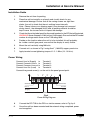
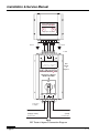
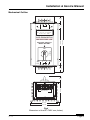
Installation & Service Manual
DPI Tester and Bypass unit
DPI TAB1
For all DPI Models
120V & 230V 50/60Hz
DIP-PROOFING
TECHNOLOGIES
INC.
LEADERS IN VOLTAGE-DIP PROOFING
Installation & Service Manual
Contents
Introduction ............................................................... 3
Description ................................................................ 3
Specifications ............................................................ 4
Installation Guide ...................................................... 5
Operation .................................................................. 7
Mechanical Outline ................................................... 9
Notice
IMPORTANT SAFETY INSTRUCTIONS.
SAVE THESE INSTRUCTIONS!
This manual contains important instructions that should be followed during installation
of the DPI Tester & Bypass unit.
Page 2
DPI TAB
Installation & Service Manual
Introduction
The Voltage Dip Proofing Inverter (DPI) has become an industry standard for the elimination of
process down time caused by momentary voltage sags and interruptions. Power Quality
problems exist in all distribution systems and the DPI has been successful in overcoming the
problem in a wide range of industries. In many cases the DPI is used in plant where preventative
maintenance programmes are in place. As part of these programs it has become necessary to test
the DPI to ensure that it is fully functional. This is a time consuming task even if bypass switches
were installed together with the DPI. Qualified personnel are needed to perform the tests on the
DPI using sophisticated test equipment. The time required to test a DPI ranges from 30 to 45
minutes depending on the location of the DPI and conditions at the plant.
The DPI Tester and Bypass (DPI TAB) has been developed to enable easy integration of the DPI
into preventative maintenance schedules and eliminate the need for highly skilled personnel to
perform the tests.
Description
The DPI Tester and Bypass (DPI TAB) consists of a bypass switch, monitoring electronics and
a LCD display housed in an extruded aluminum enclosure. The DPI TAB acts as a standard
bypass switch, monitors and displays the number of events served by the DPI since the last test,
the total number of events served to date, the number of days that the DPI has been in service and
the number of days that have elapsed since the last test was performed. The statistical information
is displayed on one screen for ten seconds and alternated with another screen that displays the
model number of the connected DPI and the supply voltage. To test the DPI switch to Bypass
mode and after a delay of three seconds the test results will be displayed. The DPI TAB must be
configured to test a specific DPI model when it is manufactured and is intended to be mounted
permanently with that DPI model.
DPI Tester & Bypass
Line in (Supply) 1
Common in
2
Common out
3
1
DPI
2
Bypass switch
3
Line out (Load) 4
4
Controls & sensing
Display
Test load
4 x 20
Dip-Proofing Tech.
DPI Tester & Bypass
Type: DPI TAB1
Data displayed:
DPI model
Supply voltage
Recent dips
Total dips
Days in service
Days since last test
Test result - Pass or Fail
DPI output voltage
DPI run time
Capacitor condition
Fig 1
TAB1 Block Diagram
DPI TAB
Page 3
Installation & Service Manual
Specifications
DPI Tester & Bypass
MODEL
DPI TAB1
AC INPUT SUPPLY
Single phase supply voltage:
Maximum input voltage:
Burden:
120V or 230V 50/60Hz - Specify when ordering.
+10%
7VA
TEST
Time to test:
Capacitor value:
Inverter output voltage:
3 seconds approximately.
± 20% of nominal value - Pass. Out of range - Fail.
± 5% of nominal supply voltage - Pass. Out of range - Fail.
INDICATORS
LCD:
4 lines x 20 character, backlit.
INFORMATION DISPLAYED
DPI model
Supply:
Recent dips:
Total dips:
Days in service
Days since test:
Test result:
DPI output:
DPI run time:
Capacitance:
The DPI that the TAB is configured to test.
Supply voltage.
Events served since last test, reset after new test.
Events served since installation, cumulative, non volatile.
Days that the DPI has been in operation, cumulative, non volatile.
Days since last test, reset after new test.
Pass or Fail.
DPI inverter RMS output voltage at end of test period.
DPI set run time (ms).
Storage capacitor(s) measured value expressed as a % of nominal.
TEMPERATURE
Maximum ambient working temperature:
45°C (113°F)
CUBICLE
Construction:
Height:
Width:
Depth:
Mass:
Extruded Aluminum
298mm (11.73in)
150mm (5.90in)
110mm (4.33in)
2.7kg (5.9lbs)
CONNECTION
Cable:
Screw terminal torque:
5mm2 (10 AWG) copper panel wire
1.5 - 1.8 Nm (13 - 16 lb-in)
LISTINGS
Underwriters Laboratories Inc:
not listed
ORDERING
Specify:
The DPI model that is to be tested.
Page 4
DPI TAB
Installation & Service Manual
Installation Guide
1.
Remove the unit from its packing
2.
Place the unit horizontally on a bench and visually check for any
mechanical damage. Ensure that all the casing screws are tight then
shake the unit to check that there is nothing loose internally.
Note : Please inform your shipping agent if any damage has occurred
during transit : the damaged unit(s) and all packing material should be
kept in case the insurers wish to inspect the damage.
3.
Check that the rating label specifies the model number for the DPI that will be tested.
WARNING: Never connect a 120V unit to a 230V supply. Ensure that the DPI model
number & ratings match those on the TAB rating label.
4.
Decide on the location where the unit is to be installed, this will probably
be inside a switch gear panel, ensure that the display is easily visible.
5.
Mount the unit vertically using M6 bolts.
6.
Connect unit as shown in Fig 2 using 5mm2 (10AWG) copper panel wire.
7.
Apply terminal screw tightening torque of 1.5 - 1.8Nm (13 - 16 lb-in).
Power Wiring
Connect Line In (Supply) to
Terminal 1
Connect Common Line in to
Terminal 2
Connect Common Line out to
Terminal 3
Connect Line Out (Load) to
Terminal 4
Connect the ground screw(s) on the unit to the panel ground point.
1
2*
3*
4
Ground in
Ground out
Line in
Line out
(Load)
(Supply)
Common line in
*Note: 2 & 3 linked internally.
Common line out
Fig 2
Power Wiring Diagram
DPI TAB
8.
Connect the DPI TAB to the DPI in a similar manner, refer to Fig 3 p 6.
9.
Once the unit has been mounted and the external wiring completed, power
can be applied.
Page 5
Installation & Service Manual
DIP-PROOFING
INC.
TECHNOLOGIES
System
OK
Inverter
Running
Voltage Dip Proofing Inverter
1
2
3
4
Ground
Ground
To DPI
To DPI
1
Line in
3
2
4
in
out
Common Line
Line out
Dip-Proofing Tech.
DPI Tester & Bypass
Model DPI TAB1
DIP-PROOFING
TECHNOLOGIES
DPI
Tester
&
Bypass
INC.
DPI Tester & Bypass
Model: DPI TAB1
DPI
Bypass
Line in
(Supply)
To Supply 1
Common Line
in
out
2
3
Line out
(Load)
4
Connection
to Supply
Line In
Line Out
(Supply Vnom)
(Load)
Common line
Common line
Fig 3
DPI Tester & bypass Connection Diagram
Page 6
DPI TAB
Installation & Service Manual
Operation
The DPI Tester and Bypass unit has three functions.
1. The TAB performs a test on the DPI to which it is connected to determine the
condition of the energy storage capacitors, the run time setting and the inverter output
voltage. The test is initiated by switching the Bypass switch from the “DPI” position to
“Bypass”.
2. In addition to performing tests on the DPI the TAB also monitors the DPI installation
collecting and displaying the following information.
Recent Dips: Number of events served since last test.
Total Dips: Total number of events served since installation.
Days in service: Total number of days that the DPI has been in operation.
Days since test: The number of days that have elapsed since the last test.
3. It functions as a conventional Bypass switch in applications where no-break
maintenance is required. It connects the supply directly to the load, "Bypass" position,
and disconnects the power terminals of the inverter without interrupting the supply.
When in "DPI" position the load is connected to the supply via the DPI.
When the the TAB is connected to it’s matching DPI and first energized the following
screens will be displayed:
Startup - displays for 2 seconds.
Dip-Proofing Tech.
DPI Tester & Bypass
Type: DPI TAB1
Run mode screen 1 - displays for 10 seconds, alternating with Run mode screen 2.
DPI Tester & Bypass
For use with DPI
Model: DPI52S25-12
Supply: 120Vac
Run mode screen 2 - displays for 10 seconds, alternating with Run mode screen 1.
Recent dips:
xxxx
Total dips:
xxxx
Days in service:xxxx
Days since test:xxxx
As time passes the monitored data will display on the Run mode 2 screen.
DPI TAB
Page 7
Installation & Service Manual
To initiate a test switch to Bypass mode. The display will show.
Displays for approximately 3 seconds.
DPI test in progress
Test results display until the TAB is switched from Bypass to DPI.
Test passed display.
DPI test result: OK!
DPI output: xxxVac
DPI run time: xxxxmS
Capacitance: xxx%
Or test failed display.
DPI test result:Fail
DPI output: xxxVac
DPI run time: xxxxmS
Capacitance: xxx%
When switching from Bypass to DPI after a test the display will show.
DPI capacitors
recharging
Then Run mode screen 1 & 2 will alternate every 10 seconds.
Error messages:
Displays if DPI has no output or if the DPI is no connected.
No DPI output!
Please check DPI
Page 8
DPI TAB
Installation & Service Manual
43
(1.69)
Mechanical Outline
1
3
2
4
30
(1.18)
To DPI
in
out
Common Line
Line in
Line out
Dip-Proofing Tech.
DPI Tester & Bypass
Model DPI TAB1
DIP-PROOFING
DPI Tester & Bypass
Model: DPI TAB1
306 (12.05)
INC.
160 (6.30)
TECHNOLOGIES
DPI
2
3
4
2
3
4
1
Ground Screws
110 (4.33)
32
(1.26)
43
(1.69)
To Supply 1
Line out
(Load)
30
(1.18)
Bypass
Common Line
in
out
Line in
(Supply)
140 (5.51)
150 (5.90)
Fig 4
Dimensions of the DPI TAB1 mm (inches)
DPI TAB
Page 9
Installation & Service Manual
Notes:
Page 10
DPI TAB
Installation & Service Manual
Notes:
Installation & Service Manual
DPI Tester and Bypass unit
DPI TAB1
For all DPI Models
120V & 230V 50/60Hz
Motor Control Centre
B1
B2
B3
Stop
Stop
Stop
Start
Start
Start
Interlock
Interlock
Interlock
C1
C2
C3
Voltage-Dip Proofing Inverter
1
3
Static
Switch
Bridge
Inverter
Storage
Capacitor
2
Main
Breaker
Bypass Switch
Line
Voltage
Control
Voltage
A typical DPI connection diagram
DIP-PROOFING
1941 Lake Whatcom Blvd. #112
Bellingham WA 98229
USA
LEADERS IN VOLTAGE-DIP PROOFING
e-mail: [email protected]
Web: www.dipproof.com
TECHNOLOGIES
Doc Ref. 37xx.xxx
INC.
Rev 1.0 June 17th 2005 : LPW


![Ball Valve [IND] Series Válvulas de bola Serie [IND] Vannes](http://vs1.manualzilla.com/store/data/006108485_1-8afd3e44d8b14a72fadc25f9e5dc4d20-150x150.png)