1
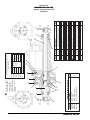
SCRUBTEC 770 S
SCRUBTEC 770 L
SCRUBTEC 784 S
SCRUBTEC 784 L
SCRUBTEC 795 S
SCRUBTEC 795 L
Operator's
Manual
U.S. Patent No. 6,760,947; No. 6,105,192; No. RE39,581 (Deluxe Machines)
EN
English (2-30)
READ THIS MANUAL
Parts List (31-67)
Form No. 70935A 11/07, Revised 12/08
Printed in the U.S.A.
READ THIS BOOK
This book has important information for the use and safe operation of this machine. Failure to read this book
prior to operating or attempting any service or maintenance procedure to your Nilfisk ALTO machine could
result in injury to you or to other personnel; damage to the machine or to other property could occur as well.
You must have training in the operation of this machine before using it. If your operator(s) cannot read this
manual, have it explained fully before attempting to operate this machine.
All directions given in this book are as seen from the operator’s position at the rear of the machine.
For new books write to: Nilfisk ALTO, 2100 Highway 265, Springdale, Arkansas 72764.
Table of Contents
Operator Safety Instructions ............................................................................................................................................................................
Introduction .......................................................................................................................................................................................................
Machine Specifications .....................................................................................................................................................................................
Procedures For Transporting .............................................................................................................................................................................
Symbols Used On S & L Models ......................................................................................................................................................................
Machine Control Panel S Models ......................................................................................................................................................................
Machine Control Panel L Models .......................................................................................................................................................................
Display Screen For L Models ...........................................................................................................................................................................
Machine Controls and Features ........................................................................................................................................................................
How To Prepare The Machine For Operation ....................................................................................................................................................
How To Install The Batteries ...........................................................................................................................................................
Battery Maintenance ......................................................................................................................................................................
How To Charge The Batteries .........................................................................................................................................................
How To Install The Brushes Or Pad Drivers ..................................................................................................................................
How To Remove The Brushes Or Pad Drivers ..............................................................................................................................
How To Operate The Machine ...........................................................................................................................................................................
How To Operate The One Touch System .......................................................................................................................................
Reprogramming One Touch ............................................................................................................................................................
How To Return One Touch To Factory Default Setting .................................................................................................................
How To Operate The Squeegee ......................................................................................................................................................
How To Fill The Solution Tank ........................................................................................................................................................
How To Traverse Machine ..............................................................................................................................................................
How To Clean A Floor .....................................................................................................................................................................
Maintenance ......................................................................................................................................................................................................
How To Correct A Problem ..............................................................................................................................................................................
Common Error Codes (SRUBTEC 770 L, 784 L & 795 L) ................................................................................................................................
Accessories ......................................................................................................................................................................................................
3
4
5
7
8
10
12
14
15
16
16
17
18
19
19
20
20
20
20
21
21
22
22
23
28
29
30
Section II Parts and Service Manual
Solution Tank Assembly ...................................................................................................................................................................................
Parts List ........................................................................................................................................................................................
Recovery Tank Assembly ................................................................................................................................................................................
Parts List ........................................................................................................................................................................................
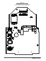
Electrical Panel Assembly S Models ................................................................................................................................................................
Parts List ........................................................................................................................................................................................
Electrical Panel Assembly L Models .................................................................................................................................................................
Parts List ........................................................................................................................................................................................
Control Panel Assembly ...................................................................................................................................................................................
Parts List ........................................................................................................................................................................................
Squeegee Swing Arm Assembly .......................................................................................................................................................................
Parts List ........................................................................................................................................................................................
Traverse System Assembly .............................................................................................................................................................................
Parts List ........................................................................................................................................................................................
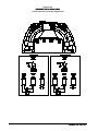
Brush Head Assembly ......................................................................................................................................................................................
Parts List ........................................................................................................................................................................................
Brush Motor .......................................................................................................................................................................................................
Gearbox
........................................................................................................................................................................................................
Imperial Transaxle Parts ...................................................................................................................................................................................
Control Panel Connection Diagram S Models ...................................................................................................................................................
Front of Machine Connection Diagram S Models .............................................................................................................................................
Control Panel Connection Diagram L Models ...................................................................................................................................................
Front of Machine Connection Diagram L Models .............................................................................................................................................
Electrical Plate Connection Diagram S Models .................................................................................................................................................
Electrical Plate Connection Diagram L Models .................................................................................................................................................
Control Housing Connection Diagram ..............................................................................................................................................................
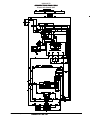
Electrical Schematic S Models ..........................................................................................................................................................................
Electrical Schematic (Top) L Models .................................................................................................................................................................
Electrical Schematic (Bottom) L Models ...........................................................................................................................................................
Page
-2-
32
33
34
35
36
37
38
39
40
41
42
43
44
45
46
47
48
49
50
51
52
54
54
55
55
56
57
58
59
60
61
Nilfisk ALTO Operator's Manual - SCRUBTEC 770 / 784 / 795
OPERATOR SAFETY INSTRUCTIONS
DANGER:
Failure to read and observe all DANGER statements could result in severe
bodily injury or death. Read and observe all DANGER statements found in
your Owner's Manual and on your machine.
WARNING:
Failure to read and observe all WARNING statements could result in injury
to you or to other personnel; property damage could occur as well. Read
and observe all WARNING statements found in your Owner's Manual and
on your machine.
CAUTION:
Failure to read and observe all CAUTION statements could result in
damage to the machine or to other property. Read and observe all
CAUTION statements found in our Owner's Manual and on your machine.
DANGER:
Failure to read the Owner's Manual prior to operating or attempting any service or
maintenance procedure to your Nilfisk ALTO machine could result in injury to you or to
other personnel; damage to the machine or to other property could occur as well. You
must have training in the operation of this machine before using it. If your operator(s)
cannot read English, have this manual explained fully before attempting to operate this
machine.
DANGER:
Operating a machine that is not completely or fully assembled could result in injury or
property damage. Do not operate this machine until it is completely assembled.
Inspect the machine carefully before operation.
DANGER:
Machines can cause an explosion when operated near flammable materials and
vapors. Do not use this machine with or near fuels, grain dust, solvents, thinners, or
other flammable materials. This machine is not suitable for picking up hazardous dust.
DANGER:
Lead acid batteries generate gases which can cause an explosion. Keep sparks and
flames away from batteries. Do not smoke around the machine. Charge the batteries
only in an area with good ventilation. Make sure that you unplug the AC charger from the
wall outlet before operating the machine.
DANGER:
Working with batteries can be dangerous! Always wear eye protection and protective
clothing when working near batteries. Remove all jewelry. Do not put tools or other
metal objects across the battery terminals, or the tops of the batteries.
DANGER:
Using a charger with a damaged power cord could result in an electrocution. Do not
use the charger if the power cord is damaged.
WARNING:
Operating this machine from anywhere other than the back of the machine could result in injury
or damage. Operate this machine only from the rear.
WARNING:
This machine is heavy. Get assistance before attempting to transport or move it. Use two able
persons to move the machine on a ramp or incline. Always move slowly. Do not turn the
machine on a ramp. If operating machine on a gradient over 2%, do not stop, turn or park.
Read the "Procedures For Transporting" in this manual before transporting.
WARNING:
Machines can topple over if guided over the edges of stairs or loading docks and cause injury
or damage. Stop and leave this machine only on a level surface. When you stop the machine,
turn the key "OFF". Set the parking brake.
WARNING:
Maintenance and repairs performed by unauthorized personnel could result in damage or
injury. Maintenance and repairs must be performed by authorized Nilfisk ALTO personnel only.
Nilfisk ALTO Operator's Manual - SCRUBTEC 770 / 784 / 795
-3-
WARNING:
Any alterations or modifications of this machine could result in damage to the machine or
injury to the operator or other bystanders. Alterations or modifications not authorized by the
manufacturer voids any and all warranties and liabilities.
WARNING:
Electrical components of this machine can "short-out" if exposed to water or moisture. Keep
the electrical components of the machine dry. Wipe the machine down after each use. For
storage, keep the machine in a dry building.
WARNING:
Operating a machine without observing all labels and instructional information could result in
injury or damage. Read all machine labels before attempting to operate. Make sure all of the
labels and instructional information are attached or fastened to the machine. Get replacement
labels and plates from your Nilfisk ALTO distributor.
WARNING:
Wet floor surfaces can be slippery. Water solutions or cleaning materials used with this type of
machine can leave wet areas on the floor surface. These areas can cause a dangerous
condition for the operator or other persons. Always put "Caution" signs around/near the area
you are cleaning.
WARNING:
Improper discharge of waste water may damage the environment and be illegal. The United
States Environmental Protection Agency has established certain regulations regarding
discharge of waste water. Also, city and state regulations regarding this discharge may be in
your area. Understand and follow the regulations in your area. Be aware of the environmental
hazards of chemicals that you dispose.
CAUTION:
Use of this machine to move other objects or to climb on could result in injury or damage. Do
not use this machine as a step or furniture. Do not ride on this machine.
CAUTION:
Your machine warranty will be voided if anything other than genuine Nilfisk ALTO parts are
used on your machine. Always use Nilfisk ALTO parts for replacement.
English
Correct Disposal of This Product (Waste Electrical & Electronic Equipment)
(Applicable in the European Union and other European countries with separate
collection systems)
This marking shown on the product or its literature, indicates that it should not be disposed with
other household wastes at the end of its working life. To prevent possible harm to the
environment or human health from uncontrolled waste disposal, please separate this from other
types of wastes and recycle it responsibly to promote the sustainable reuse of material resources.
Household users should contact either the retailer where they purchased this product, or their
local government office, for details of where and how they can take this item for environmentally
safe recycling.
Business users should contact their supplier and check the terms and conditions of the purchase
contract. This product should not be mixed with other commercial wastes for disposal.
Introduction
Introduction:
Nilfisk ALTO's newly designed Scrubtec 795, 784 & 770 automatic scrubbers are efficient and superior floor
cleaning machines. The Scrubtec 795 uses two brushes or pads to scrub a path 97 cm wide. The Scrubtec
784 uses two brushes or pads to scrub a path 84 cm wide. The Scrubtec 770 uses two brushes or pads to
scrub a path 71 cm wide. A squeegee wipes the floor while the vacuum motor removes the dirty solution from
the floor - all in one pass.
The Scrubtec 795, 784 & 770 automatic scrubbers come complete with six - 6 volt batteries, five battery
connector cables, two battery cables, either two brushes or two pad drivers, and one operator's manual.
Page
-4-
Nilfisk ALTO Operator's Manual - SCRUBTEC 770 / 784 / 795
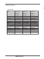
Machine Specifications
SPECIFICATIONS:
Model
Motor, Vac
Scrubtec 795 S
1 HP (.74kw) three
stage tangential
discharge
Power Supply
36 volt (6-6V batteries)
250AH, 330AH
Solution Tank
30 gallon (114 liter)
Recovery Tank
30 gallon (114 liter)
Motors, Brush (2)
1 hp PM (.74kw)
Motor Traction
.50 hp PM (.37kw)
Brushes (2)
19 inch (48cm)
w/.5" (1.5cm) overlap
Brush Speed
200 rpm
Brush Pressure
Variable 150 lbs. - 220 lbs.
Speed, Forward
Variable to 230 ft./min.
Speed, Reverse
Variable to 180 ft./min.
Charger
36V, 21A, 115V/60hz
Length
68.28 inches (173 cm)
Width - Machine
40.33 inches (102 cm)
Height
43.75 inches (112cm)
Cleaning Rate
42,000 sq ft/hr
(3,901 sq. m/hr)
Cleaning Swath
38 inch (97 cm)
Grade Cleaning
6° Incline
Weight w/Batteries (330AH) 1025 lbs. 465kg
Shipping Weight
1328 lbs. 602kg
w/batteries (330AH)
Noise (EN ISO 3744:1995)
<70 dBA
Vibration
<2.5 m/s2
(EN ISO 2631-1: 1997 (E))
Scrubtec 784 S
Scrubtec 770 S
1HP (.74kw) three
stage tagential
discharge
36 volt (6-6V batteries)
250AH, 330AH
30 gallon (114 liter)
30 gallon (114 liter)
1 hp PM (.74kw)
.50 hp PM (.37kw)
17 inch (43cm)
w/.5" (1.5 cm) overlap
200 rpm
Variable 150 lbs. - 220 lbs.
Variable to 230 ft./min.
Variable to 180 ft./min.
36V, 21A, 115V/60hz
67 inches (170 cm)
35.70 inches (91 cm)
43.75 inches (112 cm)
35,000 sq ft/hr
(3,252 sq. m/hr)
33 inch (84 cm)
6° Incline
1015 lbs. 460kg
1318 lbs. 598kg
1HP (.74kw) three
stage tagential
discharge
36 volt (6-6V batteries)
250AH, 330AH
30 gallon (114 liter)
30 gallon (114 liter)
1 hp PM (.74kw)
.50 hp PM (.37kw)
14 inch (36cm)
w/.5" (1.5 cm) overlap
200 rpm
Variable 150 lbs. - 220 lbs.
Variable to 230 ft./min.
Variable to 180 ft./min.
36V, 21A, 115V/60hz
65.0 inches (165 cm)
30.0 inches (76 cm)
43.75 inches (112 cm)
29,700 sq ft./hr
(2,750 sq ft./hr)
28 inch (71 cm)
6° Incline
1005 lbs. 456kg
1308 lbs. 593kg
<70 dBA
<2.5 m/s2
<70 dBA
<2.5 m/s2
Nilfisk ALTO Operator's Manual - SCRUBTEC 770 / 784 / 795
-5-
Machine Specifications
SPECIFICATIONS:
Model
Motor, Vac
Scrubtec 795 L
1 HP (.74kw) three
stage tangential
discharge
Power Supply
36 volt (6-6V batteries)
250AH, 330AH
Solution Tank
30 gallon (114 liter)
Recovery Tank
30 gallon (114 liter)
Motors, Brush (2)
1 hp PM (.74kw)
Motor Traction
.50 hp PM (.37kw)
Brushes (2)
19 inch (48cm)
w/.5" (1.5cm) overlap
Brush Speed
200 rpm
Brush Pressure
Variable 140 lbs. - 220 lbs.
Speed, Forward
Variable to 230 ft./min.
Speed, Reverse
Variable to 180 ft./min.
Charger
36V, 21A, 115V/60hz
Length
68.28 inches (173 cm)
Width - Machine
40.33 inches (102 cm)
Height
43.75 inches (112cm)
Cleaning Rate
42,000 sq ft/hr
(3,901 sq. m/hr)
Cleaning Swath
38 inch (97 cm)
Grade Cleaning
6° Incline
Weight w/Batteries (330AH) 1025 lbs. 465kg
Shipping Weight
1328 lbs. 602kg
w/batteries (330AH)
Noise (EN ISO 3744:1995)
<70 dBA
Vibration
<2.5 m/s2
(EN ISO 2631-1: 1997 (E))
Page
-6-
Scrubtec 784 L
Scrubtec 770 L
1HP (.74kw) three
stage tagential
discharge
36 volt (6-6V batteries)
250AH, 330AH
30 gallon (114 liter)
30 gallon (114 liter)
1 hp PM (.74kw)
.50 hp PM (.37kw)
17 inch (43cm)
w/.5" (1.5 cm) overlap
200 rpm
Variable 140 lbs. - 220 lbs.
Variable to 230 ft./min.
Variable to 180 ft./min.
36V, 21A, 115V/60hz
67 inches (170 cm)
35.70 inches (91 cm)
43.75 inches (112 cm)
35,000 sq ft/hr
(3,252 sq. m/hr)
33 inch (84 cm)
6° Incline
1015 lbs. 460kg
1318 lbs. 598kg
1HP (.74kw) three
stage tagential
discharge
36 volt (6-6V batteries)
250AH, 330AH
30 gallon (114 liter)
30 gallon (114 liter)
1 hp PM (.74kw)
.50 hp PM (.37kw)
14 inch (36cm)
w/.5" (1.5 cm) overlap
200 rpm
Variable 140 lbs. - 220 lbs.
Variable to 230 ft./min.
Variable to 180 ft./min.
36V, 21A, 115V/60hz
65.0 inches (165 cm)
30.0 inches (76 cm)
43.75 inches (112 cm)
29,700 sq ft./hr
(2,750 sq ft./hr)
28 inch (71 cm)
6° Incline
1005 lbs. 456kg
1308 lbs. 593kg
<70 dBA
<2.5 m/s2
<70 dBA
<2.5 m/s2
Nilfisk ALTO Operator's Manual - SCRUBTEC 770 / 784 / 795
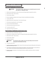
PROCEDURES FOR TRANSPORTING
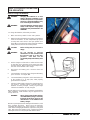
How To Put The Machine In A Van Or Truck
WARNING:
The machine is heavy. Make sure you use two able persons to assist
the machine in climbing the ramp.
1. Make sure the loading ramp is at least 2.4m long, and strong enough to support the machine.
2. Make sure the ramp is clean and dry.
3. Put the ramp in position.
4. Remove squeegee assembly, brush housings, & brushes or pad drivers before loading.
5. Turn key switch "ON".
6. Align the machine on a level surface 3.1m in front of the ramp.
7. Put the traverse speed switch in the "HI" position.
8. Press one or both forward switches.
9. Push the machine to the top of the ramp.
10. Turn the key switch "OFF".
11. Fasten the machine to the vehicle.
How To Remove The Machine From A Van Or Truck
1. Make sure there are no obstructions in the area.
2. Make sure the unloading ramp is at least 2.4m long and strong enough to support the machine.
3. Make sure the ramp is clean and dry.
4. Put the ramp in position.
5. Unfasten the machine.
WARNING:
The machine is heavy. Make sure you use two able persons to assist in
moving the machine down the ramp.
6. Turn the key switch "ON".
7. Carefully and slowly, drive the machine to the top of the ramp by pressing and holding either of the forward
switches and the reverse switch.
8. Put the traverse speed switch to the mid range speed setting. As the machine begins to travel down the
ramp, maintain a slow downward speed by pressing either of the forward switches.
9. Replace squeegee assembly, brush housings, & brushes or pad drivers after the machine is unloaded
and ready to use.
Nilfisk ALTO Operator's Manual - SCRUBTEC 770 / 784 / 795
-7-
SYMBOLS USED ON SCRUBTEC 770, 784, 795
SYMBOLS USED ON
SCRUBTEC 770 S, 784 S & 795 S
SCRUBTEC 770 L, 784 L, 795 L
Hazard Alert Symbol
On/Off Key Switch
SYMBOLS USED ON
SCRUBTEC 770 S, 784 S & 795 S
Power
SYMBOLS USED ON
SCRUBTEC 770 L, 784 L & 795 L
Squeegee
Up/Down
Additional Brush
Pressure
Traverse Speed Control
Solution
Control
Brush Up/Down
Hour Meter
Switch
Brush Up/Down
Charge/Battery
Meter
Page
-8-
Solution Control
Charge Indicator
One Touch Switch
Nilfisk ALTO Operator's Manual - SCRUBTEC 770 / 784 / 795
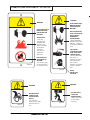
SYMBOLS USED ON SCRUBTEC 770, 784, 795
WARNING
WARNING
READ OPERATOR'S
MANUAL BEFORE
OPERATING THIS
MACHINE
READ OPERATOR'S
MANUAL BEFORE
OPERATING THIS
MACHINE
EXPLOSIVE GASES,
CAN CAUSE SEVERE
INJURY, DEATH
OR DAMAGE
TRANSFORMER.
• Keep flammable
materials away from
batteries. Charge in
a cool well ventilated
area.
RISK OF FIRE
• Use only
commercially
available floor
cleaners and
waxes intended
for machine
operation.
• Do not use
flammable
materials.
71018A
BATTERIES
CONTAIN SULFURIC
ACID. CAN CAUSE
SEVERE INJURY.
• Avoid contact with
skin eyes, or
clothing. If contact,
flush with water.
Get medical
attention. If internal.
contact call physician.
RISK OF INJURY
OR DAMAGE TO
MACHINE
• Do not turn, stop
or leave machine
on a ramp or dock.
71015A
WARNING
WARNING
71017A
MOVING PARTS.
CONTACT CAN
CAUSE SEVERE
INJURY.
• Do not place
hands or feet under
machine when in
use.
Nilfisk ALTO Operator's Manual - SCRUBTEC 770 / 784 / 795
WEAR
PROTECTIVE
EYEGEAR.
FALLING PARTS
CAN CAUSE
SEVERE INJURY.
• Make sure tank is
secure before
servicing.
71014A
-9-
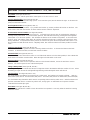
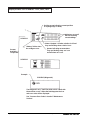
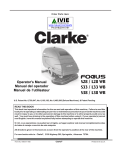
MACHINE CONTROL PANEL SRUBTEC 770 S, 784 S & 795 S
Key Switch (See Figure #1, Item "A")
The key switch turns "ON" the power to the control panel. "0" is "OFF" and "I" is "ON".
Traverse Speed Switch (See Figure #1, Item "B")
The speed control varies from low to high speed. To increase the speed, turn the knob to the right. To decrease the
speed, turn the knob to the left.
Brush Up/Down Switch (See Figure #1, Item "C")
The brush switch has two positions: "Up" positions the brushes up; "Down" positions the brushes on the floor. The
brush motors start when the brushes are down and the traverse switch is depressed.
Increase Brush Pressure Switch (See Figure #1, Item D)
This switch is used to increase the brush pressure. Increased brush pressure may be required when stripping or
cleaning heavily soiled floors. To increase brush pressure, first lower the brushes by pressing the brush up/down
switch (Item "C") to the down position. This will lower the brushes to the normal scrub position. To increase brush
pressure, press and hold the switch (Item "D") until the desired brush pressure is reached or the brush deck stops
moving downward. To reposition the brush pressure to normal scrub, press the brush up/down switch (Item "C") to
the up position and after the brush deck is completely raised, then return the switch to the down position for normal
scrub.
Solution Control Knob (See Figure #1, Item "E")
The solution control knob regulates the flow of cleaning solution to the floor. To increase the flow turn the knob
clockwise. To decrease the flow, turn the knob counter-clockwise.
Forward Switch (See Figure #1, Item "F")
The forward switch turns the traverse motor "on" and if the brush motors are in the down position, it also activates the
brush motors and solution control module. Either the right or the left switch can be used.
Reverse Switch (See Figure #1, Item "G")
The reverse switch, when used in conjunction with one of the forward switches, causes the machine to reverse
direction. The reverse speed is 70% of the forward speed.
Charge / Battery Meter (See Figure #1, Item "H")
The charge/battery meter indicates the amount of charge that is left in the batteries while the machine is in use. When
the battery pack gets too low the red light will begin flashing and the brush/pad motors will shut off.
Circuit Breakers (See Figure #1, Item "I"-"M")
The circuit breaker reset buttons are located on the control panel. The breakers are located as follows: Item I & J Brush Motors (35A); Item K - Traverse Motor (30A); Item L - Vac Motor (25A); Item M - Actuator Motor, Brush Head (5A)
If a circuit breaker trips, determine which motor is not operating and turn the key switch "OFF". Wait five minutes and
push the reset button back in. Turn the key switch "ON", and try again. An authorized service person should be
contacted if the breaker trips again.
Hour Meter (See Figure #1, Item "N")
The hour meter indicates the number of hours the machine has operated. It runs only when the machine is moving
forward or reverse.
Page
-10-
Nilfisk ALTO Operator's Manual - SCRUBTEC 770 / 784 / 795
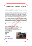
MACHINE CONTROL PANEL SRUBTEC 770 S, 784 S & 795 S
B
G
F
F
E
C
D
A
M
L
K J
I
H
N
Figure #1
Nilfisk ALTO Operator's Manual - SCRUBTEC 770 / 784 / 795
- 11 -
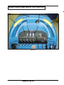
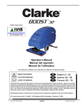
MACHINE CONTROL PANEL SRUBTEC 770 L, 784 L & 795 L
Key Switch (See Figure #2 Item "A")
The key switch turns "ON" the power to the control panel. "O" is "OFF" and "I" is "ON".
Traverse Speed Switch (See Figure #2, Item "B")
The speed control varies from low to high speed. To increase the speed, turn the knob to the right. To decrease the
speed, turn the knob to the left.
Squeegee Up/Down Switch (See Figure #2, Item "C")
The squeegee switch is used to raise and lower the squeegee and to turn on and off the vacuum motor. The squeegee will lower and the vacuum motor will turn on when the switch is placed in the lower position. To raise the squeegee, place the switch in the up position. The vacuum motor will stop, after a short delay, when the switch is placed in
the up position.
The middle switch position is used for the one touch control. The squeegee will raise and lower and the vacuum will
turn on and off automatically when the one touch control function is used. NOTE: The squeegee switch must be in
the middle position for the squeegee and vacuum to operate properly with the one touch feature.
Brush Up/Down Switch (See Figure #2, Item D)
To lower brush head, push the brush switch in the down (+) position. To increase brush pressure, continue to push
the brush switch in the down (+) position until the desired pressure is reached or until brush head travel stops. The
brush motors will start and solution will flow (provided the solution is turned "ON") when the machine begins to
traverse. To raise the brush head, push the brush switch in the up (-) position until the brush head travel stops or
desired position is reached.
Solution Flow Control (See Figure #2, Item "E")
The solution flow switch regulates the flow of chemical solution to the floor. To increase the flow, push the solution
flow switch in the down (+) position until desired flow is reached. To decrease the flow, push the solution flow switch
in the up (-) position until the desired flow is reached. To shut off the solution, push the solution flow switch in the up
(-) position until no indicators are visible on the display. NOTE: DO NOT run dry! NOTE: No solution will flow when
the machine does not traverse.
Forward Switch (See Figure #2, Item "F")
The forward switch turns the traverse motor "on" and if the brush motors are in the down position, it also activates the
brush motors and solution control module. Either the right or the left switch can be used.
Reverse Switch (See Figure #2, Item "G")
The reverse switch, when used in conjunction with one of the forward switches, causes the machine to reverse
direction. The reverse speed is 70% fo the forward speed.
One Touch (See Figure #2, Item "H")
The one touch button is a green button that lowers and raises the brush head and squeegee with one touch. NOTE:
For more information about the one touch feature see the section "How to Operate the Machine".
LCD Display (See Figure #2, Item "I")
The main display indicates the state of battery charge, brush head, solution and squeegee status. It will also display
machine run hours and error codes. NOTE: When the battery charger gets too low the battery display will begin
flashing and the brush/pad motors will shut off.
Display Button (See Figure #2, Item "J")
Pressing the black display button will toggle between the main machine functions and the hour meter. The hour
meter indicates the number of hours the machine has operated. It displays brush motor, vacuum motor, traverse
motor and total key on hours.)
Page
-12-
Nilfisk ALTO Operator's Manual - SCRUBTEC 770 / 784 / 795
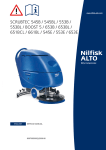
MACHINE CONTROL PANEL SRUBTEC 770 L, 784 L & 795 L
Circuit Breakers (See Figure #2, Item "K", "L", "M")
The circuit breaker reset buttons are located on the control panel. The breakers are located as follows:
"M" - Brush Motors (35A); Item N - Key Switch (5A).
Item "L" and
If a circuit breaker trips, determine which motor is not operating and turn the key switch "OFF". Wait five minutes and
push the reset button back in. Turn the key switch "ON", and try again. An authorized service person should be
contacted if the breaker trips again.
G
B
F
F
D
C
I
E
A
M
L
K J
H
Figure #2
Nilfisk ALTO Operator's Manual - SCRUBTEC 770 / 784 / 795
- 13 -
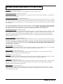
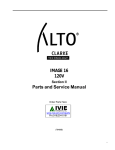
Display Screens For SCRUBTEC 770 L, 784 L, 795 L
Position arrow indicating current position
of squeegee (up or down)
3
Indicators are on all
the time showing
current settings.
SCREEN 1
Water “droplets” off when solution is off and
they are flashing when solution is on.
Screens
Available
to Operator
“Battery” blinks when
low voltage occurs.
Arrows indicating vacuum status.
They are flashing when vac is on
and off when vac is off.
SCREEN 2
Example
SCREEN 3 (Diagnostic)
The Diagnostic only. It will not show unless a fault with
the machine occurs. When the fault happens the icon
and error code will be displayed.
See "Common Error Codes" at end of "Maintenance
Section".
Page
-14-
Nilfisk ALTO Operator's Manual - SCRUBTEC 770 / 784 / 795
EN
MACHINE CONTROLS & FEATURES
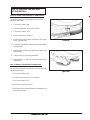
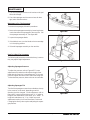
Squeegee Lift Handle ("S Class" models only) See
Figure #3a, 3b, & 3c.
The squeegee lift handle is located below the control
handles on the right side. It is used to raise or lower the
squeegee. The vac motor is turned on when the handle is
lowered.
Parking Brake (Optional)See Figure #4.
The parking brake prevents movement of the machine.
The brake is located on the left hand side of the transaxle
motor. Turn the key switch off or disconnect the power to
the battery to apply the brake.
There is a mechanical lever located on the brake. This
lever is an override. To manually release the brake, rotate
the lever toward the rear of machine (counter clockwise).
To return the brake to normal or to apply the brake, rotate
the lever towards the front of the machine (clockwise).
NOTE: If the lever is left in the override position, the
brake will not function with the key switch, and the
machine will not operate.
Figure #3a
CAUTION: Do not activate the brake while the machine is moving.
Float Shut Off See Figure #5.
The shut-off switch for the vac motor is located in the
recovery tank. It automatically turns off the vac motor
when the recovery tank is full.
Figure #3b
Figure #4
Figure #5
Nilfisk ALTO Operator's Manual - SCRUBTEC 770 / 784 / 795
Figure #3c
- 15 -
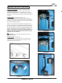
HOW TO PREPARE THE MACHINE
FOR OPERATION
38720B
The Scrubtec machines use six 6-volt batteries. The
batteries are located in the battery compartment
under the recovery tank.
38720B
38722B
How To Install The Batteries
To Install the batteries, follow this procedure:
1. Turn key switch off.
38722B
2. Make sure both tanks are empty.
3. Disconnect the hoses from the recovery tank
(upper tank) & unplug the vac motor and float
switch.
38720B
38722B
4. Remove the tank support bracket.
Figure #6a
5. Remove the recovery tank.
Lifting batteries without
help could result in an
injury. Get help to lift the
batteries. The batteries are
heavy.
WARNING:
Working with batteries can
be dangerous. Always
wear eye protection and
protective clothing when
working near batteries.
NO SMOKING!
38722B
WARNING:
38722B
6. Place the batteries in the solution tank as
shown in figures 6a and 6b.
38722B
7. Connect the battery cables between
batteries and install long battery cable
assembly as indicated. See figure 6a and 6b.
Figure #6b
8. Install the tank, reconnecting hoses and
plugging in vac motor and float switch
connectors. Install tank support bracket.
NOTE: Charge the batteries before using the
machine.
Page
-16-
Nilfisk ALTO Operator's Manual - SCRUBTEC 770 / 784 / 795
HOW TO PREPARE THE MACHINE
FOR OPERATION
Battery Maintenance
The electrical power to operate the machine comes from the
storage batteries. Storage batteries need preventive maintenance.
WARNING:
Correct fill level
Working with batteries can be dangerous. Always wear eye protection and protective clothing when
working near batteries.
NO SMOKING!
To maintain the batteries in good condition, follow these
instructions:
Figure #7
1. Keep the electrolyte at the correct level. The correct
level is between 6.35mm below the bottom of the tube
in each cell and above the tops of the plates. Check
the level of the electrolyte each time you charge the
batteries. See figure #7.
NOTE: Check the level of electrolyte prior to charging the
batteries. Be sure the plates in each cell are covered with
electrolyte . Do not top off the cells prior to charging the
battery. Electrolyte expands during charging. As a result,
the electrolyte could overflow from the cells. Always top off
the cells with distilled water after charging.
CAUTION:
Irreversible damage will occur to
the batteries if the electrolyte level
does not cover the plates. Keep the
electrolyte at the correct level.
CAUTION:
Machine damage and discharge
across the tops of the batteries can
occur if the batteries are filled
above the bottom of the tube in
each cell. Do not fill the batteries
up to the bottom of the tube in each
cell.
Wipe any acid from the
machine or the tops of the batteries. Never add acid to a battery
after installation.
CAUTION:
Tap water may contain contaminants that will damage batteries.
Batteries must be re-filled with distilled water only.
2. Keep the tops of the batteries clean and dry.
Keep the terminals and connectors clean. To clean the
top of the batteries, use a damp cloth with a weak
solution of ammonia or bicarbonate of soda solution.
To clean the terminals and connectors, use a terminal
and connector cleaning tool. Do not allow ammonia or
bicarbonate of soda to get into batteries.
3.
Keep the batteries charged.
Nilfisk ALTO Operator's Manual - SCRUBTEC 770 / 784 / 795
- 17 -
HOW TO PREPARE THE MACHINE
FOR OPERATION
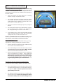
How To Charge The Batteries
WARNING:
Charging the batteries in an area
without adequate ventilation could
result in an explosion. To prevent an
explosion, charge the batteries only
in an area with good ventilation.
WARNING:
Lead acid batteries generate gases
which could explode. Keep sparks
and flames away from batteries. NO
SMOKING!
To charge the batteries, follow this procedure:
1.
Make sure the key switch is in the “OFF” position.
2.
Before charging the batteries, the battery compartment
needs to be vented. To vent compartment, tip up the
recovery tank until it locks in the open position (see
figure #8). To close the tank, pull up on the arm and then
slowly lower the tank to the closed position.
3.
CAUTION:
Before raising tank, be sure tank is
empty.
WARNING:
Do not operate or perform
maintenance on the machine while
the recovery tank is in the open
position.
The tank can be
accidentally bumped and it may slam
shut.
Figure # 8
Put the charger on a flat surface. Make sure the vents
on the sides are at least two inches away from walls
and other objects. Make sure there are no objects near
the vents on the bottom of the charger.
4.
Disconnect the battery pack connector from the
batteries.
5.
Connect the DC connector on the charger to the battery
pack connector. See figure #8A.
6.
Connect the battery charger AC cord located at the rear
of the machine to a 10 amp (min) 230V properly
grounded wall receptacle.
7.
Observe indicator light to ensure the charging process
has started. Flashing light(s) indicates that the
batteries are being charged. Steady on green light
indicates the batteries are fully charged.
Figure 8A
NOTE: Make sure you plug into a circuit that is not loaded by
other equipment. Wall breakers may be tripped and no
charge will occur.
WARNING:
Never charge a GEL battery with an
unsuitable battery charger. Carefully
follow the instructions given by the
manufacturer of the batteries and
battery charger.
NOTE: To prevent permanent damage to the batteries, avoid
their complete discharge. Never leave the batteries
completely discharged, even if the machine is not being
used. When recharging the batteries, keep the recovery tank
open. After every 20 recharging cycles, check the level of the
electrolyte and if necessary top off with distilled water.
Page
-18-
Nilfisk ALTO Operator's Manual - SCRUBTEC 770 / 784 / 795
HOW TO PREPARE THE MACHINE
FOR OPERATION
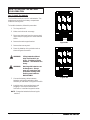
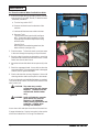
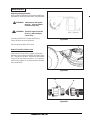
How To Install The Brushes Or Pad Drivers
To install the brushes or pad drivers on the machine,
follow this procedure:
1. Turn the key switch "ON".
2. Put the brush switch in the "UP" position.
3. Turn the key switch "OFF".
4. Go to the front of the machine.
5. Unlatch right and left brush housings and remove
them. See figure #9.
Figure #9
6. Put a brush or pad driver under the brush motor plate.
See figure #10.
7. Align the lugs on the motor gimbal with the slots in the
brush gimbal.
8. Pull the brush up until the gimbal locks.
9.
Repeat steps 6, 7, and 8 to install the second brush
or pad driver.
How To Remove The Brushes Or Pad Drivers
To remove the brushes or pad drivers from the machine,
follow this procedure:
Figure #10
1. Turn the key switch "ON".
2. Put the brush switch in the "UP" position.
3. Turn the key switch "OFF".
4. Go to the front of the machine.
5. Push down on two sides of the brush or pad driver until
the gimbals release.
Nilfisk ALTO Operator's Manual - SCRUBTEC 770 / 784 / 795
- 19 -
HOW TO OPERATE THE MACHINE
How to Operate the One Touch System ("L Class" models only)
One touch cleaning is a feature on the new Scrubtec Walk-behind
Scrubber. The factory defaults for this setting are two bars of
brush pressure and four bars for solution flow and squeegee in
the down position.
1.
Press and release the green button for all cleaning
functions to begin, see figure #11, item A.
2.
The squeegee and brush head lower to the floor and the
vacuum starts. NOTE: The squeegee switch must be in the
center position for the squeegee to operate with the one
touch feature, see figure #11, item B.
3.
The brushes and solution will begin only when you begin to
traverse.
4.
The cleaning will be at the factory default settings, however
you can reprogram these settings to your specifications.
See “Reprogramming One Touch” section below.
5.
To end cleaning process, press the green button again and
solution will stop; brushes will raise; after a short delay
squeegee will raise; and the motor will turn off.
A
B
Figure #11
NOTE: It is intended that this be done while traversing. If you
stop and do it, some solution can be left on the floor.
Reprogramming One Touch
If you do not want to use the factory default settings, you may
reprogram the setting by following the procedures below:
1.
Place the machine in the desired scrub condition by using
the one touch and individual switches.
2.
Press and hold the green one touch button until you see the
LCD display flash, then release the button. NOTE: The time
required should be approximately 5 seconds.
3.
When you activate or deactivate the one touch, it will now be
set to your preference for cleaning. These settings will
remain until you disconnect power or reprogram them.
NOTE: When programming one touch, be sure squeegee
is in automatic (middle) position, otherwise you may
program squeegee either up or down all the time.
How to Return One Touch to Factory Default Settings
To restore the factory settings, follow the procedures below:
1.
Press and hold the green one touch button until you see the
LCD display flash two times (5 seconds between flashes),
see figure 11. NOTE: The time required for this will be
approximately 10 seconds.
2.
The settings should be returned to 4 bars of solution and 2
bars of brush pressure. NOTE: The squeegee vac switch
must be in the middle position for default settings to work.
Page
-20-
Nilfisk ALTO Operator's Manual - SCRUBTEC 770 / 784 / 795
HOW TO OPERATE THE MACHINE
How To Operate the Squeegee
("S Class" models only)
The squeegee wipes the floor while the vacuum motor
removes the dirty solution from the floor. Use your right
hand to lower or raise the squeegee handle. To operate the
squeegee, follow this procedure:
1. To lower the squeegee and start the vac motor move
the squeegee lever to the right and down. See figure
#12.
2. To raise the squeegee, lift the squeegee lever up.
See figure #13.
Figure #13
Figure #12
Note: The center position lets the vac motor continue to
run with the squeegee off the floor to avoid drips.
How to Fill The Solution Tank
CAUTION:
Make sure water or solution
does not enter the opening for
the vacuum motor See figure #14.
The solution tank can be filled in the front or through the
clear drain hose at the rear of the machine. To fill the
solution tank follow this procedure:
1. Remove the solution tank lid. See figure #15.
Figure #14
2. Fill the solution tank with water.
3. Add a cleaning chemical to the water. for the
correct amount, follow the directions shown on the
container.
WARNING:
Water solutions or cleaning materials
used with this type of machine can
leave wet areas on the floor surface.
These areas can cause a dangerous
condition for the operator or other
persons. Always put CAUTION signs
near the area you are cleaning.
WARNING:
Machines can ignite flammable
materials and vapors. Do not use
with or near flammables such as
gasoline, grain dust, solvents, and
thinners. Only use a cleaning concentration recommended by the chemical
manufacturer.
WARNING:
Nilfisk ALTO recommends a maximum water temperature of
120°F(49°C)
Figure #15
4. Replace the solution tank lid.
5. When filling the machine from the rear, position the
clear drain hose against bracket and insert hose
as shown in figure 16. Solution level can be viewed
from the back of the machine.
Nilfisk ALTO Operator's Manual - SCRUBTEC 770 / 784 / 795
Figure #16
- 21 -
HOW TO OPERATE THE MACHINE
How To Traverse Machine
NOTE: Put the machine in the slow traverse speed (see
figure #17). Use the machine in an area that has no
furniture and objects until you can do the following:
1. Move the machine in a straight direction, forward and
backward.
2. Stop the machine safely.
3. Move the machine in a straight direction after you turn
the machine.
To move the machine, follow this procedure:
1. Turn the key switch “ON” position.
2. Put the brush switch in the "UP" position.
Figure # 17
3. Raise the squeegee.
4. To go forward, push one or both of the yellow forward
switches (see figure #18).
5. To stop the machine, release the yellow forward
switches.
6. To go backward, push in on the white reverse button and
one of the yellow forward switches at the same time (see
figure #19).
7. To turn the machine, push the rear of the machine to the
side.
8. When you stop the machine, turn the key switch "OFF".
How to Clean a Floor
WARNING: Water solutions or cleaning materials used with this type of machine
can leave wet areas on the floor
surfaces. These areas can cause a
dangerous condition for the operator
or other persons. Always put CAUTION signs near the area you are
cleaning.
Figure #18
To clean a floor, follow this procedure:
1. Put the water and a cleaning chemical in the clean
solution tank.
2. Turn the key switch "ON". If one touch feature is used,
press the green button and proceed to step 6 (deluxe
models only).
3. Lower the squeegee.
Figure #19
4. Put the brush switch in the "DOWN" position.
5. Adjust the flow of clean solution to the flow desired.
6. Move the machine across the floor in the forward
direction.
7.
Make a 1800 turn.
NOTE: When you make more passes across the floor, let
the brushes clean approximately 5cm of the
area already cleaned by the brushes.
NOTE: During most cleaning procedures, apply and
remove the solution in one operation.
Page
-22-
Nilfisk ALTO Operator's Manual - SCRUBTEC 770 / 784 / 795
HOW TO OPERATE THE MACHINE
How to Clean a Very Dirty Floor
To clean a very dirty floor, follow this procedure:
1. Apply solution to the floor.
2. Do not lower the squeegee.
3. Do not activate the vacuum motor.
4. Lower the brushes and scrub the floor.
5. Leave the solution on the floor long enough for the
solution to begin cleaning the floor.
6. Scrub the floor again with additional solution, picking
up all the solution with the squeegee
MAINTENANCE
WARNING: Maintenance and repairs must be
done by authorized personnel only.
WARNING: Always empty the solution tank and
recovery tank before doing any
maintenance.
WARNING: Keep all fasteners tight.
These Maintenance Procedures Must Be Done Every Day
Keep the machine clean, it will need fewer repairs and
have longer life.
Do These Procedures When You Begin Your Work
Period
Figure #20
1. Turn off key switch.
2. Unplug charger from AC outlet and wrap cord around
bracket at rear of machine.
3. Make sure the recovery tank lid is on correctly (see
figure #20).
4. Make sure the Screen filter over the vacuum motor
is clean and in position (see figure #20).
5. Make sure the valve on the recovery drain hose is
clean. Tightly close the valve.
6. Make sure brush housings and skirts are in
position on the brush head.
7. Make sure the brushes are in position and
installed correctly
8. Check the installation of the squeegee and
squeegee hose.
Nilfisk ALTO Operator's Manual - SCRUBTEC 770 / 784 / 795
- 23 -
MAINTENANCE
Do These Procedures When You End Your Work
1. Drain the solution tank (Figure #21, item A) and the
recovery tank (Figure #21, item B). To drain the tanks
, follow this procedure:
a. Turn the key switch “OFF”.
B
b. Remove the drain hose from the back of the
machine.
A
c. Put the end of the hose over a drain or bucket.
d. Recovery Tank:
Turn the valve housing to the left (see figure
#22). To open the valve completely, turn the
housing fully to the left and pull the housing
off of the valve.
Figure #21
Solution Tank:
When hose is lowered below water level, the
water will drain (see figure 23).
2. Flush the tanks. To flush the tanks, put clean water
in the tank through the opening on top of the tank.
3. If a tank or drain hose has an obstruction, use a high
pressure water hose to flush the tank or hose. Put the
water hose into the drain hose.
4. Leave the tanks and the drain valves open to dry in the
air.
5. Check the squeegee blade. Use a cloth to clean the
squeegee blade. If the squeegee blade is damaged
or worn, turn or replace the blade.
Figure #22
6. Check and clean the recovery lid gasket. Use a mild
cleaning solution and rinse the parts in clean water.
Check the batteries and add distilled water as needed.
The correct level is within 6.35mm of the bottom of the
tube in each cell.
CAUTION: Tap water may contain
contaminants that will damage
batteries. Batteries must be
re-filled with distilled water
only.
Figure #23
WARNING: Lead acid batteries generate
gases which can cause an
explosion. NO SMOKING.
Always wear eye protection and
protective clothing when
working near batteries.
Use a clean cloth and wipe the surface of the machine.
Charge the batteries. See the instruction in the section
of this book called “How To Charge The Batteries”.
Page
-24-
Nilfisk ALTO Operator's Manual - SCRUBTEC 770 / 784 / 795
MAINTENANCE
These Maintenance Procedures Must Be Done Every
Week:
WARNING:
Maintenance and repairs must be
done by authorized personnel only.
Always empty the solution tank and
the recovery tank before doing any
maintenance. Keep all fasteners
tight.
WARNING: Always wear eye protection and protective clothing when working near
batteries. Do not put tools or other
metal objects across the battery terminals or the tops of the batteries.
CAUTION: To prevent damage to the machine,
and discharge across the tops of the
batteries, do not fill the batteries
above the bottom of the tube in each
cell. Wipe any acid from the machine or the tops of the batteries. Do
not add acid to battery after installation.
Figure #24
NOTE: Always turn off key switch before servicing the
machine.
WARNING: Always wear eye protection and
protective clothing when working
near batteries. NO SMOKING!
1. To inspect batteries, tip up recovery tank until it locks
in up position. See Figure #24.
2. Disconnect the batteries. Use a cloth and a solution
of ammonia or bicarbonate of soda to wipe the top of the
batteries. Clean the battery terminals. Reconnect the
batteries.
Figure #25
3. Check the hoses for leaks, obstructions and other
damages.
4. Check and clean the filter screen in the solution hose.
To clean the screen, follow this procedure:
a. Turn the connector to the left.
b. Remove and clean the filter screen.
c. Install the filter screen in the hose. Turn the
connector to the right to connect the hose.
5. Use a grease gun to lubricate the drive wheel and the
casters. See figure #25.
6. Check tire pressure. Tire pressure should be about 50
psi (3.45 bar).
Nilfisk ALTO Operator's Manual - SCRUBTEC 770 / 784 / 795
- 25 -
MAINTENANCE
7. Check the squeegee and the scrub brushes or the pad
drivers for damage.
8. Check the squeegee and the vacuum hose for dam
age, leaks and obstructions.
Maintenance For The Squeegee
To remove the squeegee, follow this procedure:
1. Remove the squeegee assembly by loosening the two
knobs that attach the squeegee to the machine. Pull
the squeegee assembly off. See figure #26.
Figure #26
2. Inspect the squeegee blade.
3. If the blade is worn, turn the blade so that a new edge
is in the wiping position.
4. Reinstall squeegee assembly on the machine.
How To Adjust The Squeegee
The following adjustments are set at the factory, however
they may require slight adjustment.
Figure #27
Adjusting Squeegee Pressure:
To adjust the pressure, refer to Figure #27. Proper
adjustment will produce a uniform flare along the rear
blade when the machine is moved forward. To increase
pressure, tighten the nuts on each side of the swing arm.
To decrease the pressure, loosen the nuts on each side.
Adjusting Squeegee Tilt:
The tilt of the squeegee causes the rear blade to raise up
in the center or on the ends, depending on which
direction the tilt is changed. For tilt adjustment, refer to
figure # 28. Loosen left and right screw "X". In order to
bring the rear blade down in the center, tip "Y" down. To
bring both ends down, tip "Y" up. Make very small
adjustments and try it until a uniform flare is achieved.
Changing the tilt may also require readjusting the squeegee pressure.
Page
-26-
Figure #28
Nilfisk ALTO Operator's Manual - SCRUBTEC 770 / 784 / 795
MAINTENANCE
Adjusting Squeegee Blades
When properly installed the front blade should be approximately 0.12 above the rear blade. See figure #29.
WARNING: Maintenance and repairs
must be done by authorized personnel only .
WARNING: Electrical repairs must be
done by authorized personnel only.
0.12" (3.0 mm)
Consult your Nilfisk ALTO Authorized Service
Person to do the service procedures.
Figure #29
Use only genuine Nilfisk ALTO parts.
How to Clean the Solution Line
If the solution line becomes clogged, pull the filter
assembly out from behind the brush housing (Figure
30). Turn solution vavle off. Remove the filter screen
(Figure 31, B) and clean or replace it. Turn solution
valve back on (figure 31, A) and push filter assembly
back inside frame.
Figure #30
A
B
Figure #31
Nilfisk ALTO Operator's Manual - SCRUBTEC 770 / 784 / 795
- 27 -
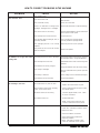
HOW TO CORRECT PROBLEMS IN THE MACHINE
PROBLEM
The machine does not remove all the
water from the floor.
The batteries do not give the normal
running time.
The cleaning is not even.
CAUSE
ACTION
The squeegee is up
Lower the squeegee.
The vacuum tank is full.
Drain the tank.
The screen filter is dirty.
Clean the screen filter.
There is an obstruction or damage in the
squeegee, squeegee hose or standpipe.
Remove the obstruction or repair the damage.
The vacuum motor is not running.
Check for tripped breaker. Have an authorized
service person make repairs.
The squeegee hose is disconnected.
Connect the hose.
The squeegee blade is damaged, worn, or
incorrectly installed.
Turn or replace the squeegee blade.
Correctly install the squeegee blade.
The squeegee pressure is not correctly
adjusted.
Adjust the pressure of the squeegee.
The gaskets on the cover of the recovery
tank are damaged.
Replace the gaskets.
The battery terminals are dirty or damaged.
Clean the terminals and connectors. Replace
the damaged cables. Charge the batteries.
The electrolyte level is too low.
Add distilled water to each cell and charge the
batteries.
The batteries are not fully charged.
Charge the batteries for a full 16 hour charge.
The charger is damaged.
Have an authorized service person repair the
charger.
The battery is defective.
Check voltage of each cell while discharging.
The batteries are disconnected.
Connect the batteries.
The scrub brushes or pads are worn.
Replace the scrub brushes or pads.
There is damage to the brush assembly,
casters or the solution valve.
Have an authorized service person make
the needed repairs.
The brush motors are not running
Check for tripped breaker, reset. Check
for loose connections.
The solution level is low.
Fill the solution tank.
NOTE: If the motors continue to stop
consult an authorized service person.
The machine does not run.
The machine loses power.
Reset the circuit breaker.
Check wire connection to traverse motor.
Replace the fuses.
Check the batteries connections.
Check parking brake overide lever
position (if installed)
NOTE: If the motors continue to stop,
consult an authorized service person.
Page
-28-
Nilfisk ALTO Operator's Manual - SCRUBTEC 770 / 784 / 795
SCRUBTEC 770 L, 784 L, 795 L
Common Error Codes
ERROR
CODE
CAUSE
ACTION
3100
3101
3102
3103
3104
3105
Probable short circuit of
output device.
Check the traction, brush and vac motor
connections on the trio and check wiring
from these connectors down to the
traction, brush and vac motors.
7600
Open circuit on brush motors
or brush motor wiring.
Check the brush motor connection on
the trio and check the wiring from this
connector down to the brush motor.
7603
Possible short circuit on
brush motors or wiring.
7800
Open circuit on traction motor.
Check the traction motor connection on
trio and wiring down to motor.
7802
Traction motor current has
exceeded current limit for the
fold back time.
Excessive driving up an incline, or
machine driven up against an obstacle
or step.
9000
Brushes not fitted.
Brushes
2F01
Drive system activated prior
to turning key switch "ON".
Release traverse switch and reactivate.
NOTICE: IF ERROR CODE/FAULT OCCURS TURN KEY SWITCH OFF AND THEN BACK ON.
For further codes and explanations, contact a Nilfisk ALTO Service Center.
Nilfisk ALTO Operator's Manual - SCRUBTEC 770 / 784 / 795
- 29 -
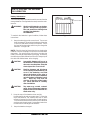
Accessories - 11/06
ACCESSORIES
Description
Part No.
Power Wand System Kit
10892A
ESP Recycle System Kit
10894A
Soft Caster Asm.
52127A
Care Kit
14607A
Squeegee Asm., Optional 74 cm (770 model only)
18818A
Drive Wheel, Foam Filled
59955A
Imperial Electric Parking Brake Kit
10684A
Battery Maintenance System
53390A
Machine
770
770
770
770
770
770
770, 784
784
784
795
795
795
770
770
770
770
770, 784
784
784
795
795
Blade
Inner
Inner
Inner
Inner
Inner
Inner
Inner
Inner
Inner
Inner
Inner
Inner
Outer
Outer
Outer
Outer
Outer
Outer
Outer
Outer
Outer
Type
Optional
Optional
Optional
Optional-Grout
Optional
Optional
Optional
Optional
Optional-Grout
Optional
Optional-Grout
Optional
Optional
Optional
Optional
Optional
Optional
Optional
Optional
Optional
Optional
Brushes:
Pad Drivers:
Page
-30-
Optional Squeegee Blades
Material
Urethane, Ribbed (60)
Urethane, Notched, 1.5mm (80)
Urethane, Ribbed (60)
Urethane, Notched 1.5mm (80)
Gum, Notched (35)
Neoprene, Notched (80)
Gum, Notched (35)
Urethane, Ribbed (60)
Urethane, Notched 1.5mm (80)
Urethane, Ribbed (60)
Urethane, Notched, 1.5mm (80)
Neoprene, Notched (80)
Nitrile, Solid (40)
Nitrile, Solid (40)
Gum, Solid (35)
Gum, Solid (35)
Gum, Solid (35)
Gum, Solid (35)
Nitrile, Solid (40)
Nitrile, Solid (40)
Gum, Solid (35)
Size
43.2 cm
43.2 cm
43.2 cm
43.2 cm
43.2 cm
35.6 cm
35.6 cm
35.6 cm
35.6 cm
35.6 cm
48.3 cm
48.3 cm
48.3 cm
48.3 cm
48.3 cm
Description
Poly
Grit-Heavy
Grit-Medium
Grit-Lite
Soft Nylon
Poly
Grit-Heavy
Grit-Medium
Grit-Lite
Soft Nylon
Poly
Grit-Heavy
Grit-Medium
Grit-Lite
Soft Nylon
Size
Part No.
48.3 cm
43.2 cm
35.6 cm
17524B
17520C
17521C
Length
65.7 cm
65.7 cm
91.1 cm
91.1 cm
91.1 cm
65.7 cm
102.2 cm
102.2 cm
104.1 cm
116.8 cm
116.8 cm
116.8 cm
71.4 cm
97.8 cm
97.8 cm
71.4 cm
110.4 cm
107 cm
107 cm
122 cm
122 cm
Part No.
30951A
30955A
30952A
30957A
30716A
30930A
30717A
30953A
30958A
30954A
30959A
30934A
30938A
30936A
30912A
30931A
30557A
30913A
30937A
30939A
30935A
Part No.
11424B
11425B
11430B
10384A
10875A
11427B
11426B
11431B
10383A
10874A
11434B
11433B
11432B
10385A
11435B
Nilfisk ALTO Operator's Manual - SCRUBTEC 770 / 784 / 795
SCRUBTEC 770 S
SCRUBTEC 770 L
SCRUBTEC 784 S
SCRUBTEC 784 L
SCRUBTEC 795 S
SCRUBTEC 795 L
Section II
Parts and Service Manual
(70935A)
U.S. Patent No. 6,760,947; No. 6,105,192; No. RE39, 581 (Deluxe Machines)
Nilfisk ALTO Operator's Manual - SCRUBTEC 770 / 784 / 795
- 31 -
Nilfisk ALTO
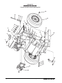
SCRUBTEC 770 / 784 / 795
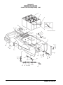
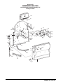
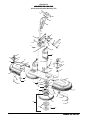
Solution Tank Assembly Drawing 11/06
1
2
3
46
35
47
33
34
36
4
37
6
40
38
7
39
8
9
48
41
10
42
43
30
To Electrical Panel
5
44
11
12
31
32
31
12
30
29
13
22
28
21
19
23
20
16
17
18
15
14
45
24
Page
-32-
21
21 27 49 26 25
24
Nilfisk ALTO Operator's Manual - SCRUBTEC 770 / 784 / 795
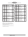
Nilfisk ALTO
SCRUBTEC 770 / 784 / 795
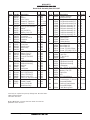
Solution Tank Assembly Parts List 11/06
Ref #
1
2
2
2
3
4
5
6
7
8
9
10
11
12
13
14
15
16
17
18
19
20
21
22
23
24
25
26
27
28
29
30
31
32
33
34
35
36
37
38
39
40
40
41
42
43
44
45
46
46
47
48
49
Part No. Description
881317
891384
842406
842406
40860A
40613A
40612A
61713A
170892
170915
962027
50966A
30590E
60480A
80108A
30598A
51346A
872010
98465A
980657
962139
61590A
59614A
53571A
30453A
822802
30445A
50358A
838517
830214
50359A
53568A
980614
85395A
30655A
81105A
980645
962798
30498A
38020A
920296
50966A
930090
85614A
962666
962522
87054A
80289A
50248A
40856A
40857A
40855A
81109A*
54088A
Battery - 250 AH - 6 Volt
Battery - 330 AH - 6 Volt
Series Cable - 9" ("S" Models)
Series Cable - 9" ("L" Models)
Fused Cable ("L" Models)
Battery Cable, Black ("L" Models)
Battery Cable, Red ("L" Models)
Tank Support Bracket
Washer, Lock 1/4
Screw, 1/4-20 x 3/4 Hex
Screw, 8-32 x 1/2 PN
Latch
Solution Tank
Hose Bracket
Screw, 10-24 x 1/2 PN
Drain Hose
Spring, Hose
Hose Clamp
Clamp, Metal
Washer, Lock 1/4
Screw, 1/4-20 x 5/8 Hex
Hose Hanger Bracket
Battery Drain Valve
Hose Clamp
Hose
Elbow
Solution Hose
Connector
Filter Screen
Hose Adapter
Solution Adapter
Hinge
Washer, 1/4 External
Screw, 1/4-20 x 1/2 PN
Front Cover
Nut, 3/8-16 ESNA
Washer, 3/8 Flat
Screw, 10-24 x 1/2 PN
Solution Lid
Strap
Nut, 10-24 ESNA
Keeper, Latch
Rivet, 5/32 x 9.16 (Prior to DL0055)
Screw, 8-32 x 3/4 PN (starting w/DL0055)
Screw, 10-24 x 3/4 PN
Screw, 3/8-16 x 2 Hex
Washer, 3/8 Fender
Screw, 10 x 1/2 Tapping PN
Clamp, Hose
Cable, Electrical Panel ("S" Models)
Cable, Battery Charger ("L" Models)
Cable, Battery ("S" Models)
Nut, 8-32 SS Elastic Lock
Valve, Shut-Off
Nilfisk ALTO Operator's Manual - SCRUBTEC 770 / 784 / 795
Qty
6
6
5
4
1
1
1
1
2
2
2
1
1
1
4
1
1
1
1
1
1
1
1
4
1
1
2
1
1
1
1
1
6
6
1
2
2
1
1
1
2
1
2
2
1
2
2
2
2
1
1
1
2
1
- 33 -
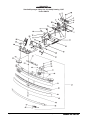
Nilfisk ALTO
SCRUBTEC 770 / 784 / 795
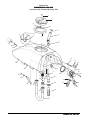
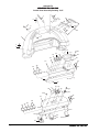
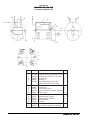
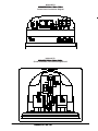
Recovery Tank Assembly Drawing 6/07
1
2
5
3
7
6
8
3
4
9
37
38
39
10
11
12
36
15
23
35
13
22
16, 16A
17
9
26
18
14
34
27
33
24
28
20
20
32
20
21
11
29
19
25
30
31
Page
-34-
Nilfisk ALTO Operator's Manual - SCRUBTEC 770 / 784 / 795
Nilfisk ALTO
SCRUBTEC 770 / 784 / 795
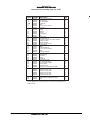
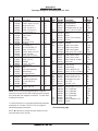
Recovery Tank Assembly Parts List 11/07
Ref #
Part No. Description
1
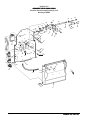
2
3
4
5
6
7
8
9
10
11
12
13
14
15
16
16A
17
18
19
20
21
22
23
24
25
26
27
28
29
30
31
32
33
34
35
36
962798
30057A
920296
30065B
38020A
962666
58069A
39338B
837304
82100A
41809A
43402A
920797
643418
58533A
45019A
40830A
87026A
85728A
43401A
872010
674110
962957
52206A
30620A
35192A
30227A
30226A
52560A
30225A
832002
35165A
61591A
87622A
80043A
30068A
30673A
30697A
30698A
30699A
30700A
30701A
40002A
56459A
87612A
37
38
39
Screw, 10-24 x 1/2 PN
Recovery Lid
Nut, 10-24 ESNA
Gasket, Lid
Strap
Screw, 10-24 x 3/4 PN
Vac Filter
Stand Tube
O-Ring
Locknut
Contact
Housing, Blue
Nut
Gasket, Vac
Vac Motor Spacer
Vac Motor (order 2 each #11 and #19)
Brushes, Carbon
Washer, 1/4 Flat
Screw, 1/4-20 x 4 Hex
Housing, Black
Clamp
Vac Exhaust Hose
Screw, 10-16 x 1/2 PN
Chain
Squeegee Adapter
Squeegee Hose
Drain Housing
Drain Plug
O-Ring
Drain Body
Drain Valve Clamp
Recovery Drain Hose
Recovery Tank Support
Washer, Nylon
Shoulder Screw
Hinge Pin (included with item #36)
Tank, Recovery, 770 S
Tank, Recovery, 770 L
Tank, Recovery, 784 S
Tank, Recovery, 784 L
Tank, Recovery, 795 S
Tank, Recovery, 795 L
Float Switch (includes items, #38 & 2 ea. #11& #12)
Strain Relief (included in item #37)
Seal
Qty
1
1
2
1
1
1
1
1
2
1
4
2
1
1
3
1
2
3
3
2
3
1
2
1
1
1
1
1
1
1
1
1
1
1
1
2
1
1
1
1
1
1
1
1
1
NOTE: indicates a change has been made since the last publication
of this manual.
Nilfisk ALTO Operator's Manual - SCRUBTEC 770 / 784 / 795
- 35 -
Nilfisk ALTO
SCRUBTEC 770 S / 784 S / 795 S
Electrical Panel Assembly Drawing 2/07
Drawing # 10849E
41
39
40
38
10
36
47
34
5
28
27
26
15
45
44
37
2
50
1
5
6
18
5
13
14
12
30
7
11
17
31
5
5
35
9
16 20
32
46
49
18
29
10
48
33
21
43
42
25
24
20
19
51
23
6
22
3
8
7
4
Page
-36-
Nilfisk ALTO Operator's Manual - SCRUBTEC 770 / 784 / 795
Nilfisk ALTO
SCRUBTEC 770 S / 784 S / 795 S
Electrical Panel Assembly Parts List 2/07
Drawing # 10849E
Ref #
Part No. Description
1
2
3
4
5
6
7
8
9
10
11
12
13
14
15
16
17
18
19
20
21
22
23
24
25
26
27
28
29
30
31
32
33
34
35
36
37
38
39
40
41
42
43
44
45
46
47
48
49
50
51
962980
962139
85391A
30594A
81104A
87007A
980651
80030A
980614
902731
920110
53569A
80285A
83302A
854849
170781
193951
83307A
61589A
54764A
54763A
40736A
40125A
41801A
41802A
61682A
40735A
40759A
80254A
962666
912287
920296
85700A
87026A
608210
65628A
962304
61584A
920056
61586A
61585A
438360
960510
52557A
980666
85389A
68643A
980675
962546
47388A
54436A
Screw, 6-32 x 1
Screw, 1/4-20 x 5/8
Screw, 1/4-20 x 5/8 PN
Rear Cover
Nut, ESNA 1/4-20
Washer, 1/4 Flat
Washer, 5/16 Flat
Shoulder Bolt
Washer, 1/4 External
Nylon Bearing
Nut, ESNA 5/16-18
Spacer
Screw, Set 5/16-18 x 1 3/4
Stud, 1/4-20
Insulator
Screw, Set 1/4-20 x 3/4
Trim, 8"
Stud, 1/4-20
Electrical Panel
Insert, 1/4-20
Insert, 8-32
Main Wiring Harness, Std.
Contactor, Vacuum
Contactor, Brush
Contactor, Main
Cable, Upper
Controller, Solo
Traverse Harness
Screw, 8-32 x 1
Screw, 10-24 x 3/4
Rectifier
Nut, ESNA 10-24
Screw, 1/4-20 x 1
Washer, 1/4 Flat
Spacer
Lever, Cable
Screw, Set 5/16-18 x 1/2 (must use red Loctite)
Squeegee Lift Bracket
Nut, ESNA #6-32
Shaft
Squeegee Lift Lever
Spring
Shoulder Screw
Squeegee Knob
Washer, 3/8 External
Screw, 3/8-16 x 5/8
Wear Plate
Washer
Screw, 10-24 x 1/2
Switch
Plug, Hole 1 3/8"
Nilfisk ALTO Operator's Manual - SCRUBTEC 770 / 784 / 795
Qty
2
2
2
1
10
3
6
2
2
2
4
4
4
1
1
1
1
11
1
4
2
1
1
1
1
1
1
1
2
1
1
1
1
2
1
1
2
1
2
1
1
1
1
1
1
1
1
2
2
1
1
- 37 -
Nilfisk ALTO
SCRUBTEC 770 L / 784 L / 795 L
Electrical Panel Assembly Drawing 2/07
Drawing # 10855E
29
30
18
10
5
21
20
35
31
32
5
13
31
33
12
2
1
5
18
16
9
15
17
27
14
7
11
6 5
2
34
5
5
26
19
37
20
25
6
3
24
22
23
28
8 7
Page
-38-
4
Nilfisk ALTO Operator's Manual - SCRUBTEC 770 / 784 / 795
Nilfisk ALTO
SCRUBTEC 770 L / 784 L / 795 L
Electrical Panel Assembly Parts List 2/07
Drawing # 10855E
Ref #
Part No. Description
1
2
3
4
5
6
7
8
9
10
11
12
13
14
15
16
17
18
19
20
21
22
23
24
25
26
27
28
29
30
31
32
33
34
35
36
37
962798
87624A
85391A
30626A
81104A
87007A
980651
80030A
57275A
980614
920110
53569A
80285A
83302A
854849
170781
193951
83307A
61589A
54764A
54763A
40742A
61680A
53424A
58409A
61681A
41802A
40854A
40743B
80105A
86004A
61595A
920296
40745A
962139
69872A
54436A
Screw
Washer, Pulley
Screw, 1/4-20 x 5/8 PN
Rear Cover
Nut, ESNA 1/4-20
Washer, 1/4 Flat
Washer, 5/16 Flat
Shoulder Bolt
Pulley
Washer, 1/4 External Lk
Nut, ESNA 5/16-18
Spacer
Screw, Set 5/16-18 x 1 3/4
Stud, 1/4-20
Insulator
Screw, Set 1/4-20 x 3/4
Trim, 8"
Stud, 1/4-20
Electrical Panel
Insert, 1/4-20
Insert, 8-32
Main Wiring Harness, Dlx
Cable, Spring
Spring, Cable
Sleeve, Spring
Cable, Upper
Contactor
Harness, Interface
Controller, Trio
Screw, 8-32 x 1 1/4
Screw, 1/4-20 x 1 1/2
Bracket, Actuator
Nut
Actuator, Squeegee
Screw, 1/4-20 x 5/8 Hex
Bracket, Pulley
Plug, Hole 1 3/8"
Nilfisk ALTO Operator's Manual - SCRUBTEC 770 / 784 / 795
Qty
1
2
2
1
10
4
6
2
1
2
4
4
4
2
2
2
1
3
1
2
2
1
1
1
1
1
1
1
1
2
2
1
1
1
2
1
1
- 39 -
Nilfisk ALTO
SCRUBTEC 770 / 784 / 795
Control Panel Assembly Drawing 11/07
7
7
12
6
9
8
4
13
3
15
16
10
1
2
3
20
23
22
17
19
21
18
24
30
32
25
28
29
31
31
32
26
30
27
30
36
9
35 34
33
17
18
24
32
37
31
28
29
40
39
26
30
38
43
30
42
44
41
Page
-40-
Nilfisk ALTO Operator's Manual - SCRUBTEC 770 / 784 / 795
Nilfisk ALTO
SCRUBTEC 770 / 784 / 795
Control Panel Assembly Parts List 11/07
Ref. #
1
2
3
4
5
6
7
8
9
10
12
13
15
16
17
18
NI
19
20
21
22
23
24
25
26
27
28
29
30
31
32
33
34
35
36
37
38
39
40
41
42
43
44
Part No.
Description
30592A
85815A
980205
85813A
920110
52556A
40750A
40738A
50962A
962262
11131A
50961A
80104A
980608
962330
40786K
40786A
40786S
40748A
40880A
40758A
40168B
40747A
962957
70962A
34264A
61739A
41431B
41423B
85391A
980614
920208
962968
40749A
47381B
55502A
70961A
61720A
41448B
41422B
44308B
920296
40898A
912226
Control Handle
Screw, 5/16-18 x 1 1/2
Washer, 5/16 Flat
Screw, 5/16-18 X 1
Nut, LK 5/16-18
Reverse Switch
Traverse Potentiometer "L"
Traverse Potentiometer "S"
Knob, Traverse
Screw, Set 8-32 x 1/2 (included w/# 8 & 36)
Switch Assembly
Spring, Switch
Screw, 10-32 x 1/2 Oval
Washer, #6 Flat
Screw, 6-32 x 3/8 Pan
Key (included w/ # 18)
Switch, Key
Spacer, Key Switch
Switch, Green Push Button
LCD Display
Switch, Black Push Button
Switch, Momentary Rocker
Switch, 3 Position Rocker
Screw, 10-16 x 1/2
Label, Control
Gasket
Panel, Control "L"
Circuit Breaker, 35A
Circuit Breaker, 5A
Screw, 1/4-20 x 5/8
Washer, 1/4 External
Nut, 1/4-20
Screw, 10-24 x 1/2
Switch, Momentary Rocker
Switch, Mantain Rocker
Knob, Control
Label, Control
Panel, Control
Circuit, Breaker, 30A
Circuit, Breaker, 25A
Solution Modulator
Nut, Lk 10-24
Meter, Battery/Charger
Meter, Hour
Qty
"L"
Qty
"S"
1
2
6
4
4
1
1
1
2
2
4
4
4
4
1
1
1
1
1
1
2
1
4
1
1
1
2
1
4
3
3
-
1
2
6
4
4
1
1
1
4
2
4
4
4
4
1
4
1
2
1
3
2
2
2
1
1
1
1
1
1
1
1
2
1
1
NOTE: indicates a change has been made since the last publication of this
manual.
Nilfisk ALTO Operator's Manual - SCRUBTEC 770 / 784 / 795
- 41 -
Nilfisk ALTO
SCRUBTEC 770 / 784 / 795
Squeegee Swing Arm Assembly Drawing 11/07
55
53 2
1
7
2
53
3
6
50
8
53
57
4
9
10
16
6
15
23
16 53
11
25
12
13
24
34
5
26
52
51
17
14
18
6
19
20
22
27
6
28
21
NOTE:
#51 and
#52 are
on top of
the
bracket
for the
"S"
models
10
29
31
30 48
56
37
33
47
41
32
42
35
43
40
38
39*
37
36
54
44
45
46
49
Page
-42-
Nilfisk ALTO Operator's Manual - SCRUBTEC 770 / 784 / 795
Nilfisk ALTO
SCRUBTEC 770 / 784 / 795
Squeegee Swing Arm Assembly Parts List 11/07
Ref #
1
2
3
4
5
6
7
8
9
10
11
12
13
14
15
16
17
18
19
20
21
22
23
24
25
26
27
28
29
30
31
32
33
34
Part No.
57275A
87623A
60452A
86004A
85730A
81104A
38021A
61679A
51613A
920110
60332A
920256
81105A
920296
962798
87624A
80015A
53423A
68016A
170915
64905A
980651
60678C
25201B
35192A
61267A
34260B
81301A
59971A
65975A
81217A
60248A
30048A
87031A
Description
Pulley
Washer, Nylon 1¼x¼x1/8
Swing Arm, Front
Screw, .25-20 x 1½
Screw, .375-16 x 1¼
Nut, Hex ESNA SS
Strap
Cable, Lower
Bumper
Nut, ESNA
Swing Arm, Rear
Nut, Hex
Nut, ESNA SS
Nut, 10-24 ESNA SS
Screw, 10-24 x .50
Washer, Nylon 1½x¼x1/8
Screw, Shoulder
Spring, Squ. Pressure
Stud
Screw, SS Hex
T Handle
Washer, Flat .312
Pivot Bracket
Knob
Hose, Squeegee Rec.
Tube Bracket
Squeegee Gasket
Nut, Jam SS
Wheel
Wheel Mount Bracket
Nut, 1/4-20 ESNA
Sleeve
Guide Wheel
Washer, 3/8 Flat
Qty
2
2
1
2
1
6
1
1
1
3
1
2
1
1
1
2
1
2
2
2
3
1
1
2
1
1
1
2
2
2
2
2
2
1
Model
All
All
All
All
All
All
All
All
All
All
All
All
All
All
All
All
All
All
All
All
All
All
All
All
All
All
All
All
All
All
All
All
All
All
Ref #
35
NOTE: When changing squeegee blades, it might be
necessary to loosen screw #39; install and secure blades
with clamp #44; then retighten screw #39. This will allow
for different thickness.
+ = Optional parts for non-standard, adjustable squeegee
assemblies on Scrubtec 770/784. See next page for
standard squeegee assemblies.
36
37
38
39
40
41*
41*
41*
41*
42*
42*
42*
42*
43
44
45
46
47
48
49
50
51
52
53
54
54
54
54
55
56
57
Part No.
69673A
69674A
69675A
69636A
80316A
38710A
38711A
38715A
38713A
62712A
80011A
37016A
30716L1
30717L2
30718L2
30763L1
30912L
30913L
30935L
30931L
62421A
62442A
62443A
62444A
62441A
86004A
170932
85702A
85816A
55722A
81217A
920208
980657
87625A
18815KL
18816KL
18817KL
18818L
81303A
54766A
87026A
Description
Qty
Squeegee Base
1
Squeegee Base
1
Squeegee Base
1
Squeegee Base, 29" acc. 1
Screw, ¼-20 x 1 Flat SS 2
Spacer
2
Spacer
2
Spacer
2
Spacer, 29" accessory
2
Air Duct
1
Screw, .375-16 x 3.00
2
Grip Pad
1
Blade, Inner Linatex
1
Blade, Inner Linatex
1
Blade, Inner Linatex
1
Blade, Inner 29" Linatex 1
Blade, Outer Linatex
1
Blade, Outer Linatex
1
Blade, Outer Linatex
1
Bade, Outer 29" Linatex 1
End Clamp
1
Clamp, Weld
1
Clamp, Weld
1
Clamp, Weld
1
Clamp, Weld 29" acc.
1
Screw, .25-20 x 1.50 Hex 1
Rivet
2
Screw, .25-20 x 1.75
2
Screw, .312-18 x 1.75
2
Squeegee Strap Latch
1
Nut, ½-20
1
Nut, Hex ¼-20
1
Washer, ¼ Lock
1
Washer,Nylon 1¼x¼x1/32 4
Asm., Squeegee
1
Asm., Squeegee
1
Asm., Squeegee
1
Asm., Squeegee*
1
Nut, ¼-28
1
Insert,Threaded 5/16-24
2
Washer
4
Model
770+
784+
795
770+
All
770+
784+
795
770+
All
All
All
770+
784+
795
770+
770+
784+
795
770+
All
770+
784+
795
770+
All
All
All
All
All
All
All
All
All
770+
784+
795
770+
All
All
All
* See accessory page
NOTE: indicates a change has been made since the
last publication of this manual.
Nilfisk ALTO Operator's Manual - SCRUBTEC 770 / 784 / 795
- 43 -
Nilfisk ALTO
SCRUBTEC 770 / 784
Standard Squeegee Swing Arm Assembly Drawing 11/07
Form # 10847A
Page
-44-
Nilfisk ALTO Operator's Manual - SCRUBTEC 770 / 784 / 795
Nilfisk ALTO
SCRUBTEC 770 / 784
Standard Squeegee Swing Arm Assembly Parts List 11/07
Form # 10847A
Ref #
1
2
3
4
5
6
7
8
9
10
11
12
13
14
15
16
17
18
19
20
21
22
23
24
25
26
27
Part No.
57275A
87623A
60452A
86004A
85730A
81104A
38021A
61679A
51613A
920110
60332A
920256
81105A
920296
962798
87624A
80015A
53423A
68016A
170915
64905A
980651
60678C
25201B
35192A
61267A
34260B
Description
Pulley
Washer, Nylon 1¼x¼x1/8
Swing Arm, Front
Screw, .25-20 x 1½
Screw, .375-16 x 1¼
Nut, Hex ESNA SS
Strap
Cable, Lower
Bumper
Nut, ESNA
Swing Arm, Rear
Nut, Hex
Nut, ESNA SS
Nut, 10-24 ESNA SS
Screw, 10-24 x .50
Washer, Nylon 1½x¼x1/8
Screw, Shoulder
Spring, Squ. Pressure
Stud
Screw, SS Hex
T Handle
Washer, Flat .312
Pivot Bracket
Knob
Hose, Squeegee Rec.
Tube Bracket
Squeegee Gasket
Qty
2
2
1
2
1
4
1
1
1
1
1
2
1
1
1
2
1
2
2
2
3
1
1
2
1
1
1
Ref #
28
29
30
31
32
33
34
35
36
37
38
39
40
41
42
43
44
45
46
47
48
49
50
51
52
53
54
Part No.
81217A
920208
980657
87625A
81303A
87026A
87031A
962720
980657
10803KL
60243A
30049B
81104A
60254A
60358A
53185A
30048A
60272B
930086
50835A
60252A
30557L
30058A
30717L1
80011A
81301A
80280A
Description
Nut, ½-20
Nut, Hex ¼-20
Washer, ¼ Lock
Washer,Nylon 1¼x¼x1/32
Nut, ¼-28
Washer
Washer, 3/8 Flat
Screw, ¼ -20 x ½ Hex
Washer, ¼ Lock
Squeegee Asm.
Bracket, Sq. Wheel
Wheel, Squeegee
Nut, ¼ -20
Bolt, Shoulder 5/16 x 2 ¼
Shim, Squeegee Wheel
Ring, 3/8 ID Snap
Wheel, Gide 4" Diam.
Channel, Sq. Weldment
Rivet, 3/16 x .450 Alum.
Latch, Sq. Clamp
Strap, Clamp Sq. Ret.
Blade, Rear Linatex
Spacer, Squeegee
Blade, Front Linatex
Screw, 3/8-16 x 3
Nut, 3/8-16 Jam SS
Nut, Squeegee,Backup
Qty
1
1
1
4
1
4
1
4
4
N/A
2
4
2
2
2
2
2
1
2
1
1
1
1
1
2
2
2
NOTE: When changing squeegee blades, it might
be necessary to loosen screw #52; install and secure
blades with clamp #47; then retighten screw #52. This
will allow for different thickness.
NOTE: indicates a change has been made since the
last publication of this manual.
Nilfisk ALTO Operator's Manual - SCRUBTEC 770 / 784 / 795
- 45 -
Nilfisk ALTO
SCRUBTEC 770 / 784 / 795
Traverse System Assembly Drawing 2/05
18
24
25
26
27
16
8
23
10
9
7
6
5
15
7
23
4
19
28 19
14
20
3
3
29
2
30
1
11
21
30
32
13
31
13
12
Page
-46-
Nilfisk ALTO Operator's Manual - SCRUBTEC 770 / 784 / 795
Nilfisk ALTO
SCRUBTEC 770 / 784 / 795
Traverse System Assembly Parts List 2/05
Ref #
1
2
3
4
5
6
7
8
9
10
11
12
13
14
Part No.
66531A
836711
81104A
69877A
85811A
57275A
87623A
86004A
962288
85700A
920110
899769
81105A
59116E
15
16
85730A
59969A
59955A
81221A
980614
61594A
65963A
87625A
80011A
81207A
170883
58419A
980205
69639A
980645
962244
980638
32417B
18
19
20
21
23
24
25
26
27
28
29
30
31
32
NI
Description
Swing Arm Pin
Hair Pin
Nut, .25-20 ESNA
Swing Bracket
Screw, .312-18 x .75
Cable Pulley
Washer, Nylon 1¼x¼IDx.120
Screw, .25-20 x 1.50
Screw, .375-16 x 1
Screw, .25-20 x 1
Nut, .312-16 ESNA
Caster Assembly
Nut, .375-16 ESNA
Transaxle, Imperial
(see page 51 for parts)
Screw, Hex
Wheel Assembly*
Wheel, Foam Filled (opt.)
Lug Nut, 50-20 UNF
Washer, Star Lock .25
Main Frame
Transaxle Mount
Washer, Nylon 1¼x¼IDx3/32
Screw, 3/8-16 x 3
Nut, 3/8-16
Washer, Lock 3/8
Stud, 3/8M x 3/8F
Washer, .25 Fender
Strap, Static
Washer, Flat 3/8
Screw, 3/8-16 x ¾
Lockwasher 3/8
Wheel Cover
Qty Model
1
All
1
All
2
All
1
All
2
All
1
All
2
All
1
All
6
All
1
All
2
All
2
All
12
All
1
All
4
2
2
6
3
1
2
2
2
2
2
2
2
1
6
4
4
2
All
All
All
All
All
All
All
All
All
All
All
All
All
All
All
All
All
All
*30039A tube, inner (included in item #16) 1 Ref.
Nilfisk ALTO Operator's Manual - SCRUBTEC 770 / 784 / 795
- 47 -
Nilfisk ALTO
SCRUBTEC 770 / 784 / 795
Brush Head Assembly Drawing 2/05
1
2
3
4
5
55
6
8
1
9
7
2
10
11
54
12
49
50
51
49
47
48
13
53
20
14
15
16
17
46
18
19
13
45
52
44
43
27
42
40
39
41
38
37
20
21
30
22
29
28
23
36
31
27
26
25
24
32
35
17
34
Page
-48-
33
Nilfisk ALTO Operator's Manual - SCRUBTEC 770 / 784 / 795
Nilfisk ALTO
SCRUBTEC 770 / 784 / 795
Brush Head Assembly Parts List 11/07
Ref #
1
2
3
4
4A
4A
5*
6
7
8
9
10
11
11
12***
13
14
15
16
17
18
19
20
21
22
23
24
25
26
27
28
29
30
31
32
33
Part No.
82501A
766780
38723A
52497A
52499A
40910A
40866A
980673
920278
980626
67705B
63032A
85838A
41601A
40645A
45036B
170915
48703A
50248A
30455A
81104A
87007A
38014A
962992
55721A
30574A
30583A
30355A
38246A
782002
30453A
722021
81109A
962244
980638
962495
838301
833802
962737
Description
Qty Model
Pin
2 All
Hair Pin
2 All
Nylon Spacer
2 All
Actuator & Tube Asm.
1 S series
Actuator & Tube Asm.
1 L series
Potentiometer (Circuit Board) 1 All
Housing, Potentiometer
1 All
Washer
4 All
Nut, Jam 50-20
16 All
Washer, Lock .50
8 All
Sleeve Bearing
8 All
Linkage Bar
4 All
Screw, .50-201.50
8 All
Connector
4 All
Housing
4 All
Brush Motor 1.00 HP
2 All
Screw, Hex
4 All
Electric Valve
1 All
Hose Clamp
2 All
Hose
1 All
Nut, .25-20 ESNA
5 All
Washer, Flat .25
2 All
Solution Splitter
1 All
Screw, 8-32x.62 SS
4 All
Latch
1 All
Left Brush Housing
1 28
Left Brush Housing
1 33
Left Brush Housing
1 38
Left Skirt
1 38
Clamp
2 All
Brush Hose
2 All
Hose Clamp
2 All
Nut, 8-32 ESNA SS
4 All
Screw, .375-16x.75
8 All
Washer, Lock .375
8 All
Screw, .25-20x1.00Pn Hd 6 All
Brush Holder Spring
2 All
Gimbal, Female
2 All
Screw, 10-16x.88
6 All
(Pad Driver Only)
Ref #
34
35
36
37
38
39
40
41
42
43
44
45
46
47
48
49
50
51
52
53
54
55
NI
NI
**NI
Part No. Description
56941A Center-Lock Asm.
(Pad Driver Only)
11427B Poly Brush Assembly-14
11424B Poly Brush Assembly-17
11434B Poly Brush Assembly-19
11426B Grit Brush Assembly-14
11425B Grit Brush Assembly-17
11433B Grit Brush Assembly-19
17521C Pad Driver Assembly-14
17520C Pad Driver Assembly-17
17524B Pad Driver Assembly-19
962714 Screw,.312-18x.75 Soc.
34400B Gimbal, Male
61658A Gimbal Collar
59856A Rubber Washer
66232A Brush Plate-28
61587A Brush Plate-33
66234A Brush Plate-38
85811A Screw, .312-18x.75 Hex
85610A Screw, .375-16x2.5 SS Pn
85616A Screw, 10-22x.62 Pn SS
69186A Latch Tab
82004A "T" Nut 10-32
55451A Keeper
30575A Right Brush Housing
30584A Right Brush Housing
30247A Right Brush Housing
980638 Lockwasher
920248 Nut, .375-16 Jam Thin ESNA
59950A Guide Wheel
980645 Washer, Flat .375
38247A Right Skirt
915102 Key
65966A Brush Head Mount
920110 Nut, .312-18 ESNA
40910A Potentiometer, Cir. Board
(for part # 52499A)
40866A Housing, Potentiometer
(for part # 52499A)
77091A Label, Moving Parts
Qty Model
2 All
2
2
2
2
2
2
2
2
2
2
2
2
2
1
1
1
4
1
11
1
12
1
1
1
1
1
2
1
2
1
2
1
6
1
28
33
38
28
33
38
28
33
38
All
All
All
All
28
33
38
All
All
38
All
38
All
28
33
38
All
All
All
All
38
All
All
All
L Series
1
L Series
2
All
*Used only as required to square up linkage bars #9 to the frame.
**Attach to Brush Motor.
***Includes Item #11
NOTE: indicates a change has been made since the last
publication of this manual.
Nilfisk ALTO Operator's Manual - SCRUBTEC 770 / 784 / 795
- 49 -
Nilfisk ALTO
SCRUBTEC 770 / 784 / 795
Brush Motor #45036A 2/05
13
7
12
12
1
13
2
Seam Location
3
14
16
4
Rotation
5
15
6
17
8
9
10
11
Ref #
Page
-50-
Part No. Description
1
2
3
4
5
46734A
40318A
902654
902550
51840A
6
7
8
9
10
11
12
13
14
15
16
17
50520A
56480A
962546
50517A
448396
40826A
55657A
55656A
59805A
50515A
80501A
54238A
Stator Assembly (w/Magnets & Clips)
Armature Asm.(w/B.E. & F.E. bearings)
Bearings B.E.
Bearing F.E.
Commutator Bracket Assembly
(w/Brush BRD Assembly Leads)
Commutator Bracket
Strain Relief
Brush Board Screw
Brush Board Asm. (w/springs & brushes)
Brush Spring
Brush Assembly
Lead Assembly, Positive
Lead Assembly, Negative
Helical Washer
Thru Bolt
Shaft Key
B.E. Bracket Assembly (Gear Box)
Qty
1
1
1
1
1
1
2
2
1
4
4
1
1
1
2
1
1
Nilfisk ALTO Operator's Manual - SCRUBTEC 770 / 784 / 795
Nilfisk ALTO
SCRUBTEC 770 / 784 / 795
Gear Box #54238A 2/05
9
8
7
6
5
4
3
2
1
Ref #
1
2
3
4
5
6
7
8
9
NI
Part No.
57846A
507641
52050A
56668A
51176A
58316A
902605
54883A
58144A
Description
Ring, Snap
Seal, Oil, Small
Cap End
O'Ring
Bearing, Large
Shaft & Gear, Gearbox
Bearing, Small
Housing
Seal, Oil Large
Darina Grease
Nilfisk ALTO Operator's Manual - SCRUBTEC 770 / 784 / 795
Qty
1
1
1
1
1
1
1
1
1
4oz.
- 51 -
Page
-52-
Part No.
53384A
53385A
80121A
80122A
3
2
4
17
5
6
Parking Brake Spare Parts
Description
Pad, Friction
Hub, Shaft
Key, 4 MM - Hub
Set Screw, M3 - Hub
1
7
8
To replace coupler
remove these two
screws (Black)
to separate the
motor from gearbox
to allow access to
coupler
9
Qty
1
1
1
1
10
4
16:1 Ratio
36 VDC
15
Cont
Volt
AMP.
Duty
Date
11
Ser. No.
Mount
Shaft
4BC-2800
1200
Ins. Cl.
Model
RPM
.50
12
1
Nilfisk ALTO Operator's Manual - SCRUBTEC 770 / 784 / 795
17
16
1
2
3
4
5
6
7
8
9
10
11
12
13
14
15
Ref #
Flange
Tang
HP
F
PERMANENT MAGNET MOTOR
MFG. IN USA
10357A
36508A
53374A
53375A
53376A
53377A
53378A
53379A
53380A
53381A
52663A
69195A
45048A
51720A
30074A
53382A
53383A
54282A
53435A
ALTO
Part #
13
4
2
3
1
Description
Wheel Flange Kit (includes Flange,
Studs, Key, Snap Rings & Shims)
Rubber Mount
Axle Oil Seal
Axle Bearing
Short Axle
Output Gear
Input Plug
Outer Pinion Bearing
Pinion
Inner Pinion Bearing
Steel Ring, Coupler
Rubber Coupler
Motor
Brushes w/Springs (Set of 4)
Motor Brush Cap (internal Threads)
Motor Brush Cap (External Threads)
Long Axle
Gearbox Asm w/o motor
Miter Gear
16
14
15
2
2
2
4
1
1
1
1
1
1
1
1
1
1
4
4
1
1
4
Qty
Nilfisk ALTO
SCRUBTEC 770 / 784 / 795
Imperial Transaxle Parts 2/05
PN 59116A
NOTES
Nilfisk ALTO Operator's Manual - SCRUBTEC 770 / 784 / 795
- 53 -
Nilfisk ALTO
SCRUBTEC 770 S / 784 S / 795 S
Control Panel Connection Diagram 2/05
Nilfisk ALTO
SCRUBTEC 770 S / 784 S / 795 S
(Front of Machine) Connection Diagram 2/05
Page
-54-
Nilfisk ALTO Operator's Manual - SCRUBTEC 770 / 784 / 795
Nilfisk ALTO
SCRUBTEC 770 L / 784 L / 795 L
Control Panel Connection Diagram
Nilfisk ALTO
SCRUBTEC 770 L / 784 L / 795 L
(Front of Machine) Connection Diagram 2/05
Nilfisk ALTO Operator's Manual - SCRUBTEC 770 / 784 / 795
- 55 -
Nilfisk ALTO
SCRUBTEC 770 S / 784 S / 795 S
Electrical Plate Connection Diagram 9/05
Page
-56-
Nilfisk ALTO Operator's Manual - SCRUBTEC 770 / 784 / 795
Nilfisk ALTO
SCRUBTEC 770 L / 784 L / 795 L
Electrical Plate Connection Diagram 9/05
Nilfisk ALTO Operator's Manual - SCRUBTEC 770 / 784 / 795
- 57 -
Nilfisk ALTO
SCRUBTEC 770 L / 784 L / 795 L
Control Housing Connection Diagram 2/05
Page
-58-
Nilfisk ALTO Operator's Manual - SCRUBTEC 770 / 784 / 795
Nilfisk ALTO
SCRUBTEC 770 S / 784 S / 795 S
Electrical Schematic 9/05
Nilfisk ALTO Operator's Manual - SCRUBTEC 770 / 784 / 795
- 59 -
Nilfisk ALTO
SCRUBTEC 770 L / 784 L / 795 L
Electrical Schematic (pages 58 - 59) 9/05
Page
-60-
Nilfisk ALTO Operator's Manual - SCRUBTEC 770 / 784 / 795
Nilfisk ALTO
SCRUBTEC 770 L / 784 L / 795 L
Electrical Schematic (pages 58 - 59) 9/05
Nilfisk ALTO Operator's Manual - SCRUBTEC 770 / 784 / 795
- 61 -
NOTES
Why Compromise
www.nilfisk-alto.com
HEADQUARTERS
DENMARK
Nilfisk-Advance Group
Sognevej 25
2605 Brøndby
Denmark
Tel: (+45) 43 23 81 00
Fax:(+45) 43 43 77 00
E-mail: [email protected]
SALES COMPANIES
AUSTRALIA
Nilfisk-ALTO
48 Egerton St.
PO Box 6046 Silverwater
NSW 2128 Australia
Tel: (+61) 2 8748 5966
Fax: (+61) 2 8748 5960
BELGIUM
Nilfisk-ALTO
Division of Nilfisk-Advance n.v-s.a.
Dornveld/Sphere Business Park
Industrie Asse 3, nr 11-bus 41
1731 Zellik-Asse
Belgium
Tel: (+32) 02 467 60 50
Fax: (+32) 02 466 61 50
E-mail: [email protected]
AUSTRIA
Nilfisk-Advance GmbH
Nilfisk ALTO
Metzgerstrasse 68
A-5101 Bergheim bei Salzburg
Tel: (+43) 662 456 400-0
Fax: (+43) 662 456 400-34
E-mail: [email protected]
www.nilfisk-alto.at
CANADA
Clarke Canada
Part of the Nilfisk-Advance Group
4080 Sladeview Crescent, Unit 1
Mississauga, Ontario L5L 5Y5
Canada
Tel: (905)569-0266
Fax: (905) 569-8586
CZECH REPUBLIC
ALTO Ceskà republika s.r.o.
Zateckých 9-14000 Praha 4
Czech Republic
Tel. (+420) 24 14 08 419
Fax (+420) 24 14 08 439
E-mail: [email protected]
DENMARK
Nilfisk-ALTO
Division of Nilfisk-Advance A/S
Industrivej 1
9560 Hadsund
Denmark
Tel: (+45) 72 18 21 00
Fax: (+45) 72 18 21 11
E-mail: [email protected]
E-mail:[email protected]
www.nilfisk-alto.dk
Nilfisk-ALTO Food Division
Division of Nilfisk-Advance A/S
Blytækkervej 2,
9000 Aalborg Denmark
Tel: (+45) 72 18 21 00
Fax: (+45) 72 18 20 99
E-mail: [email protected]
www.nilfisk-alto.com
FRANCE
Nilfisk-ALTO
ALTO France SA
Aéroparc 1
19 rue Icare
67960 Entzheim
France
Tel: (+33) 3 88 28 84 00
Fax: (+33) 3 88 30 05 00
E-mail: info@nilfisk-alto-fr
www.nilfisk-alto.com
GERMANY
Nilfisk-ALTO
Division of Nilfisk-Advance AG
Guido-Oberdorfer-Str. 10
89287 Bellenberg
Germany
Tel: (+49) (0) 180 5 37 37 37
Fax: (+49) (0) 180 5 37 37 38
E-mail: [email protected]
www.nilfisk-alto.de
GREECE
Nilfisk-Advance SA
8, Thoukididou str.
164 52 Argiroupolis
Greece
Tel: (+30) 210 96 33443
Fax: (+30) 210 96 52187
E-mail: [email protected]
NORWAY
ALTO Norge AS
Bjørnerudveien 24
1266 Oslo
Norway
Tel: (+47) 22 75 17 70
Fax: (+47) 22 75 17 71
E-mail: [email protected]
www.nilfisk-alto.no
PEOPLE’S REPUBLIC OF CHINA
Nilfisk-Advance (Shenzhen) Ltd
Blok 3, Unit 130, 1001 Honghua Road
Int. Commercial & Trade Center
Fuitan Free Trade Zone
518038 Shenzhen
P.R. China
Tel.: (+86) 755 8359 7937
Fax: (+86) 755 8359 1063
POLAND
Nilfisk-Advance Sp. Z.O.O.
05-800 Pruszków
ul. 3-go MAJA 8
Poland
Tel.: (+48)22 738 37 50
Fax: (+48) 22 738 37 51
[email protected]
www.nilfisk-alto.pl
HOLLAND
Nilfisk-ALTO
Division of Nilfisk-Advance BV
Camerastraat 9
NL-1322 BB Almere
Tel: (+31) 36 5460 760
Fax: (+31) 36 5460 761
E-mail: info @nilfisk-alto.nl
www.nilfisk-alto.nl
PORTUGAL
Nilfisk-ALTO
Division of Nilfisk-Advance Lda.
Sintra Business Park
Zona Industrial Da Abrunheira
Edificio 1, 1oA
P-2710-089 Sintra
Tel.: (+35) 808 200 537
Fax: (+35) 121 911 2679
E-mail: [email protected]
www.nilfisk-alto.com
HONG KONG
Nilfisk-Advance Ltd.
2001 HK Worsted Mills Ind'l Bldg.,
31-39 Wo Tong Tsui St.
Kwai Chung,
Hong Kong
Tel.: (+852) 2427 5951
Fax: (+852) 2487 5828
RUSSIA
Nilfisk-Advance LLC
127015 Moskow
Vyatskaya str. 27, bid. 7
Russia
Tel: (+7) 495 783 96 02
Fax: (+7) 495 783 96 03
E-mail: [email protected]
HUNGARY
Nilfisk-Advance Kereskedelmi Kft.
II. Rákóczi Ferenc út 10
2310 Szigetszentmiklos-Lakihegy
Hungary
Tel: (+36) 24 475 550
Fax: (+36) 24 475 551
E-mail: [email protected]
Sales: [email protected]
Service: [email protected]
www:nilfisk-advance.hu
SINGAPORE
Nilfisk-Advance Pte. Ltd.
Nilfisk-ALTO Division
40 Loyang Drive
Singapore 508961
Tel: (+65) 6 759 9100
Fax: (+65) 6 759 9133
ITALY
Nilfisk-ALTO
Divisione di Nilfisk-Advance A/S
Strada Comunale della Braglia, 18
26862 Guardamiglio (LO)
Italy
E-mail: [email protected]
JAPAN
Nilfisk-Advance, Inc.
1-6-6 Kita-shinyokohama, Kouhoku-ku,
Yokohama, 223-0059
Japan
Tel.: (+81) 45 548 2571
Fax: (+81) 45 548 2541
MALAYSIA
Nilfisk-Advance Sdn Bhd
Sd 14, Jalan KIP 11
Taman Perindustrian KIP
Sri Damansara
52200 Kuala Lumpur Malaysia
Tel: (+60) 3 603 6275 3120
Fax: (+60) 3 603 6274 6318
E-mail: [email protected]
SPAIN
Nilfisk-ALTO
Division of Nilfisk-Advance S.A.
Torre D'Ara
Paseo del Rengle, 5 Pl. 10
E-08302 Mataró
Tel: (+34) 902 200 201
Fax: (+34) 93 757 8020
E-mail: [email protected]
www.-nilfisk-alto.com
SWEDEN
ALTO Sverige AB
Member of Nilfisk-Advance Group
Aminogatan 18, Box 4029
S-431 04 Mölndal
Sweden
Tel: (+46) 31 706 73 00
Fax: (+46) 31 706 73 40
E-mail: [email protected]
www.nilfisk-alto.se
TAIWAN
Nilfisk-Advance Taiwan Branch
No. 5, Wan Fang Road
Taipei
Taiwan, R.O.C.
Tel.: (+866) 227 002 268
Fax: (+886) 227 840 843
THAILAND
Nilfisk-Advance Co. Ltd.
89 Soi Chokechai-Ruammitr
Viphavadee-Rangsit Road
Ladyao, Jatuchak, Bangkok 10900
Thailand
Tel: (+66) 2 275 5630
Fax: (+66) 2 691 4079
TURKEY
Nilfisk-Advance Professional Temizlik
Ekipmanlari Tic. A.S.
Necla Cad. NI.: 48
Yenisahra / Kadiköy
Istanbul
Turkey
Tel.: (+90) 216 470 08 - 60
Fax: (+90) 216 470 08 - 63
www.nilfisk-advance.com
UNITED KINGDOM
Nilfisk-ALTO
Division of Nilfisk-Advance Ltd.
Bowerbank Way
Gilwilly Industrrial Estate
Penrith Cumbria CA11 9BQ
Great Britian
Tel.: (+44) (0) 1768 868995
Fax: (+44) (0) 1768 864713
E-mail: [email protected]
www.nilfisk-alto.co.uk
VIETNAM
Nilfisk-Advance Representative Office
No. 46 Doc Ngu Str.
Ba Dinh Dist.
Hanoi
SR. Vietnam
Tel.: (+84) 4 761 5642
Fax: (+84) 4 761 5643
E-mail: [email protected]
USA
Clarke
2100 Highway 265
Springdale
Arkansas 72764
USA
Tel: (+1) 479 750 8450
Fax: (+1) 479 756 4540
E-mail: customerservice
@clarkeus.com
www.ClarkeUS.com
Clarke American Sanders
2100 Highway 265
Springdale
Arkansas 72764
USA
Tel: (+1) 479 750 1000
Fax: (+1) 479 750 4540
E-mail: customerservice
@americansanders .com
www.AmericanSanders.com
Nilfisk ALTO LIMITED U.S. WARRANTY
This Nilfisk ALTO Industrial/Commercial Product is warranted to be free from defects in materials and workmanship under
normal use and service, when operated and maintained in accordance with Nilfisk ALTO's Maintenance and Operations
instructions. The warranty period is subject to the conditions stated below.
3 YEARS FOR PARTS AND 1 YEAR FOR SERVICE LABOR (See exceptions below)
Motors must be inspected for carbon motor brush wear at six-month intervals by an authorized Nilfisk ALTO repair station.
Failure to comply with the six-month inspection requirement or failure to replace worn motor brushes identified during the
inspection will void the warranty on the motors. Cost of the six-month inspection and replacement of carbon motor brushes
is the responsibility of the purchaser. In the event of a warranty claim on the motors, proof of inspection and any required
motor brush replacement must be provided. This warranty is extended only to the original purchaser for use of the product.
It does not cover normal wear parts such as electrical cable, rubber parts, hoses and motor brushes.
BATTERY WARRANTY
In addition to the items above, any original equipment Nilfisk ALTO Battery which becomes unserviceable under normal use
within a period of ninety (90) days from date of sale to the original user will be repaired or replaced with one of equal
specification at our option, F.O.B. any authorized Nilfisk ALTO Sales or Service Branch, with no charge to the user, except
transportation costs. After expiration of the above ninety (90) day period, any battery which fails under normal use will be
adjusted to the original user with a new battery of equal specification on an eighteen (18) months pro rate basis from the
date of purchase. Adjustment will be determined using the then current list price, plus transportation costs.
Warranty is rendered null and void if battery is not kept filled to the proper level with DISTILLED WATER.
Nilfisk ALTO: POLYDUR® AUTOMATIC SCRUBBER SOLUTION AND RECOVERY TANK EIGHT-YEAR U.S.
GUARANTEE
Your new Nilfisk ALTO machine has polydur Solution and Recovery Tanks. Polydur is a rotationally molded, low-density
linear polyethylene that won't crack or dent, and withstands most corrosives and temperature extremes. Nilfisk ALTO
backs up your Polydur tanks with an eight-year guarantee. If a tank breaks or leaks under normal use within eight
years of the date of purchase, it will be replaced free.
Nilfisk ALTO UNIBODY FRAME FIVE-YEAR U.S. WARRANTY
Nilfisk ALTO warranties the frame for a period of five years against defects in materials and workmanship under normal
use and service.
STATED WARRANTIES ARE IN LIEU OF ALL OTHER WARRANTIES, EXPRESSED OR IMPLIED
Nilfisk ALTO's liability under this warranty is limited to repair of the product and/or replacement of parts and is given to
purchaser in lieu of all other remedies, including INCIDENTAL AND CONSEQUENTIAL DAMAGES.
THERE ARE NO EXPRESS WARRANTIES OTHER THAN THOSE SPECIFIED HEREIN. THERE ARE NO WARRANTIES WHICH
EXTEND BEYOND THE DESCRIPTION OF THE FACE HEREOF. NO WARRANTIES, INCLUDING BUT NOT LIMITED TO WARRANTY OF MERCHANTABILITY, SHALL BE IMPLIED. A warranty registration card is provided with your Nilfisk ALTO
product. Return the card to assist Nilfisk ALTO in providing the performance you expect from your new floor machine.
If a difficulty develops with the product, you should: a) Contact the nearest authorized Nilfisk ALTO repair location or contact
the Nilfisk ALTO Service Operations Department, 2100 Highway 265, Springdale, Arkansas 72764, for the nearest authorized Nilfisk ALTO repair location. Only these locations are authorized to make repairs to the product under this warranty.
(b) Return the product to the nearest Nilfisk ALTO repair location. Transportation charges to and from the repair location
must be prepaid by the purchaser. Nilfisk ALTO will repair the product and/or replace any defective parts with out charge
within a reasonable time after receipt of the product.
Nilfisk ALTO, 2100 Highway 265, Springdale, Arkansas 72764.
Nilfisk ALTO reserves the right to make changes or improvements to its machine without notice.
Always use genuine Nilfisk ALTO Parts for repair.
2100 Highway 265
Springdale, Arkansas, 72764