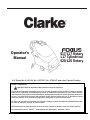
1
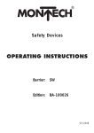
Operator's
Manual
S17/L17 Rotary
L17 Cylindrical
S20/L20 Rotary
U.S. Patent No. 6,105,192; No. 6,557,207; No. 6,760,947 and other Patents Pending
READ THIS BOOK
CAUTION: Read the Operator's Manual before using the appliance.
This book has important information for the use and safe operation of this machine. Failure to read this
book prior to operating or attempting any service or maintenance procedure to your Clarke machine
could result in injury to you or to other personnel; damage to the machine or to other property could occur
as well. You must have training in the operation of this machine before using it. If operator(s) cannot
read this manual, have it explained fully before attempting to operate this machine.
Si Ud. o sus operadores no pueden leer el Inglés, se hagan explicar este manual completamente antes
de tratar el manejo o servicio de esta máquina.
All directions given in this book are as seen from the operator’s position at the rear of the machine.
For new books write to: Clarke® , 2100 Highway 265, Springdale, Arkansas 72764.
Form No. 70899A
Clarke®
Printed in the U.S.A.
Table of Contents
Operator Safety Instructions ............................................................................................................................ 3
Machine Introduction ........................................................................................................................................ 4
S17/L17 Rotary Machine Specifications .......................................................................................................... 5
L17 Cylindrical Machine Specifications ........................................................................................................... 6
S20/L20 Rotary Machine Specifications .......................................................................................................... 7
Procedures for Transporting Machine ............................................................................................................. 8
Symbols Used on Machine .............................................................................................................................. 10
Machine Control Panel ..................................................................................................................................... 12
Machine Controls and Features ...................................................................................................................... 13
How to Prepare the Machine for Operation ...................................................................................................... 14
How to Install the Batteries ................................................................................................................ 14
Battery Maintenance ........................................................................................................................... 16
How to Charge the Batteries ............................................................................................................. 17
How to Install a Rotary Brush or Pad Driver ...................................................................................... 18
How to Remove a Rotary Brush or Pad Driver .................................................................................. 19
How to Change or Rotate Cylindrical Brushes ................................................................................. 19
How to Operate the Machine ............................................................................................................................ 20
How to Operate the Squeegee .......................................................................................................... 20
Filling the Solution Tank .................................................................................................................... 20
Operating the Machine ....................................................................................................................... 20
How to Clean a Dirty Floor ................................................................................................................. 21
Maintenance ..................................................................................................................................................... 22
Procedures Before Work is Begun .................................................................................................... 22
Procedures to Perform at the End of Work ........................................................................................ 23
Procedures to Perform Every Week ................................................................................................... 24
Maintenance for the Squeegee .......................................................................................................... 26
How to Adjust the Squeegee ............................................................................................................. 26
Accessories ...................................................................................................................................................... 27
SECTION II - Parts and Service Manual
How to Correct Problems in the Machine ........................................................................................................ 30
FOCUS S17 / L17 Final Assembly ................................................................................................................... 32
Parts List ............................................................................................................................................ 33
Recovery Tank Assembly ................................................................................................................................. 34
Parts List ............................................................................................................................................ 35
Solution Tank Assembly .................................................................................................................................. 36
Parts List ............................................................................................................................................ 37
Electrical Assembly .......................................................................................................................................... 38
Parts List ............................................................................................................................................ 39
Control Housing Assembly .............................................................................................................................. 40
Parts List ............................................................................................................................................ 41
Squeegee Lift Assembly .................................................................................................................................. 42
Parts List ............................................................................................................................................ 43
Squeegee Assembly ........................................................................................................................................ 44
Parts List ............................................................................................................................................ 45
Frame Assembly .............................................................................................................................................. 46
Parts List ............................................................................................................................................ 47
Cylindrical Brush Head Assembly ................................................................................................................... 48
Parts List ............................................................................................................................................ 49
Rotary Disk Head Assembly ............................................................................................................................ 50
Parts List ............................................................................................................................................ 51
Gearbox Assembly and Parts List ................................................................................................................... 52
Brush Motor Assembly and Parts List ............................................................................................................. 53
Transaxle Repair Parts .................................................................................................................................... 54
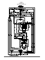
FOCUS S17/S20 Connection Diagram ........................................................................................................... 55
FOCUS S17/S20 Electrical Schematic ............................................................................................................ 56
FOCUS L17/L20 Connection Diagram ............................................................................................................ 57
FOCUS L17/L20 Electrical Schematic ............................................................................................................. 58
Page
-2-
Clarke® Operator's Manual -FOCUS S17/L17 and S20/L20
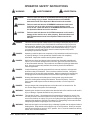
OPERATOR SAFETY INSTRUCTIONS
WARNING
AVERTISSEMENT
ADVERTENCIA
DANGER:
Failure to read and observe all DANGER statements could result in
severe bodily injury or death. Read and observe all DANGER
statements found in the Operator's Manual and on the machine.
WARNING:
Failure to read and observe all WARNING statements could result
in injury to you or to other personnel; property damage could
occur as well. Read and observe all WARNING statements found in
the Operator's Manual and on the machine.
CAUTION:
Failure to read and observe all CAUTION statements could result in
damage to the machine or to other property. Read and observe all
CAUTION statements found in the Operator's Manual and on the
machine.
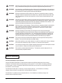
DANGER:
Failure to read the Operator's Manual prior to operating or attempting any service or
maintenance procedure to your Clarke machine could result in injury to you or to
other personnel; damage to the machine or to other property could occur as well.
You must have training in the operation of this machine before using it. If you or
your operator(s) cannot read English, have this manual explained fully before
attempting to operate this machine.
DANGER:
Operating a machine that is not completely or fully assembled could result in injury
or property damage. Do not operate this machine unless it is completely
assembled. Inspect the machine carefully before operation.
DANGER:
Machines can cause an explosion when operated near flammable materials and
vapors. Do not use this machine with or near fuels, grain dust, solvents, thinners,
or other flammable materials. This machine is not suitable for picking up hazardous
dust. Use only commercially available floor cleaning chemicals intended for
machine application.
DANGER:
Lead acid batteries generate gases which can cause an explosion. Keep sparks
and flames away from batteries. Do not smoke around the machine. Charge the
batteries only in an area with good ventilation. Make sure that the AC charger plug
is unplugged from the wall receptacle and stowed before operating the machine.
DANGER:
Working with batteries can be dangerous! Always wear eye protection and
protective clothing when working near batteries. Remove all jewelry. Do not put
tools or other metal objects across the battery terminals, or on the tops of the
batteries.
DANGER:
Using a charger with a damaged power cord could result in an electrocution. Do
not use the charger if the power cord is damaged.
WARNING:
Operating this machine from anywhere other than the back of the machine could result in
injury or damage. Operate this machine only from the rear.
WARNING:
This machine is heavy. Get assistance before attempting to transport or move it. Use
two able persons to move the machine on a ramp or incline. Always move slowly. Do
not turn the machine on a ramp. Do not use on surfaces having a gradient exceeding that
marked on the appliance. Read the "Procedures For Transporting" in this manual before
transporting as machine might topple over if not secured.
WARNING:
Machines can topple over and cause injury or damage if guided over the edges of stairs or
loading docks. Stop and leave this machine only on a level surface. When you stop the
machine, put all switches into their "OFF" position. On L17 and L20 models turn the key
switch "OFF" and remove the key.
Clarke® Operator's Manual
-FOCUS S17/L17 and S20/L20
Page -3-
WARNING:
Maintenance and repairs performed by unauthorized personnel could result in damage or
injury. Maintenance and repairs must be performed by authorized personnel only.
WARNING:
Any alterations or modifications to this machine could result in damage to the machine or
injury to the operator or other bystanders. Alterations or modifications not authorized by
the manufacturer voids any and all warranties and liabilities.
WARNING:
Electrical components to this machine can "short-out" if exposed to water or moisture.
Keep the electrical components of the machine dry. Wipe the machine down after each
use. This appliance is for dry use only and is not to be used or stored outdoors in wet
conditions.
WARNING:
Operating a machine without observing all labels and instructional information could result
in injury or damage. Read all machine labels before attempting to operate. Make sure all
of the labels and instructional information are attached or fastened to the machine. Get
replacement labels and decals from your Clarke distributor.
WARNING:
Wet floor surfaces can be slippery. Water solutions or cleaning materials used with this
type of machine can leave wet areas on the floor surface. These areas can cause a
dangerous condition for the operator or other persons. Always put "Caution" signs
around/near the area you are cleaning.
WARNING:
Improper discharge of waste water may damage the environment and be illegal.
The United States Environmental Protection Agency has established certain regulations
regarding discharge of waste water. City, state and national regulations regarding this
discharge may also be in effect in your area. Understand and follow the regulations in
your area. Be aware of the environment hazards of chemicals that you dispose.
WARNING:
Only use the brushes provided with the appliance or those specified in the Operator's
Manual. The use of other brushes may impair safety.
CAUTION:
Use of this machine to move other objects or to climb on could result in injury or damage.
Do not use this machine as a step or furniture. Do not ride on this machine.
CAUTION:
Your machine warranty will be voided if anything other than genuine Clarke parts are used
on your machine. Always use Clarke parts for replacement.
CAUTION:
This machine contains lead acid batteries. The batteries must be disposed of in an
environmentally acceptable manner.
Machine Introduction
Introduction & Machine Specifications
Clarke’s FOCUS S17/S20 and L17/L20 automatic scrubbers are efficient and superior floor cleaning
machines. The FOCUS uses one brush (rotary) to scrub a path 17" or 20" wide or 2 brushes (cylindrical)
to scrub a path 17" wide. A squeegee wipes the floor while the vacuum motor removes the dirty solution
from the floor - all in one pass.
The FOCUS S17/S20 and L17/L20 rotary comes complete with two - 12 volt batteries, one battery
charger, either one brush or one pad driver, and one operator’s manual.
The FOCUS L17 cylindrical comes complete with two - 12 volt batteries, one battery charger, two
brushes, and one operator’s manual.
Page
-4-
Clarke® Operator's Manual -FOCUS S17/L17 and S20/L20
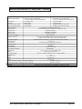
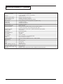
Machine Specifications (S17 Rotary and L17 Rotary)
Model
Machine Power Supply
FOCUS S17 Rotary
FOCUS L17 Rotary
24 Volt D.C., (2) 12V 130AH Wet
24 Volt D.C., (2) 12V 130AH Wet
or (2) 12V 100AH Gel Deep Cycle Batteries
or (2) 12V 100AH Gel Deep Cycle Batteries
Pad or Brush
3-Lug Driver Style
3-Lug Driver Style
Traverse
Brush Assist
1/3 HP (0.25 kW)
Traverse Forward Speed
Not Applicable
Variable to 200 ft./min (61 m/min)
Traverse Reverse Speed
Not Applicable
Variable to 140 ft./min. (43 m/min)
Battery Protection
Low Voltage Cut-Off of Brush and Solution
Motor Vacuum
3/4 HP(.569 kW) Acoustical High Efficient Tangential 3 stg
Solution Tank
11 Gallons (42 liters)
Solution Level
Calibrated Level Indicator
Recovery Tank
11 Gallons (42 liters)
Recovery Full Indicator
Electric Shut-Off
Parabolic Squeegee
Swing type with breakaway feature, No tool operation feature,
32" (81cm) hard width with 34" (86cm) flex blade width
Squeegee Operation
Reverse direction on floor and 3 - position manual lever style operation
Cleaning Swath
17" (43.2 cm)
Motor, Brush
3/4 HP (0,56 kW) 5.2:1 High Torque Gear Box
Brush / Pad Size
17" (43.2 cm)
Brush Speed
200 RPM
Brush Pressure
0-90 lbs. (0-40.8 kg)
Brush Solution Retention
Fiber Bristles
Drive Wheels
(2) 8" x 2" (20 cm x 5 cm) Neoprene tread
Caster
3½" X 1¼" (8.9 cm x 3.2 cm)
On-Board Charger
24 V D.C., 10 Amp, 115/60 or 24 V D.C., 10 Amp, 230/50
Grade Cleaning
2%
Length
48 3/4" (123.8 cm)
Width
19" (48.3 cm)
Height
42" (106.7 cm)
Weight w/batteries (130AH)
327 lbs. (148.3 kg)
345 lbs. (156.5 kg)
Shipping Weight w/Batteries (130AH)
454 lbs. (206 kg)
472 lbs. (214 kg)
Line of Sight (Operator Height = 5'8")
7.5 feet (2.3 m)
Warranty
Machine 3 Years, Polydur tanks 8 Years, Batteries 18 Months Pro-rated
Clarke® Operator's Manual
-FOCUS S17/L17 and S20/L20
Page -5-
Machine Specifications (L17 Cylindrical)
Model
Machine Power Supply
Traverse
Traverse Forward Speed
Traverse Reverse Speed
Battery Protection
Motor Vacuum
Solution Tank
Solution Level
Recovery Tank
Recovery Full Indicator
Parabolic Squeegee
Squeegee Operation
Cleaning Swath
Motor, Brush
Brush 2 per Machine
Brush Speed
Brush Pressure
Drive Wheels
Caster
On-Board Charger
Grade Cleaning
Length
Width
Height
Weight w/batteries (130 AH)
Shipping Weight w/Batteries (130AH)
Line of Sight -Operator Height = 5'8"
Warranty
Page
-6-
FOCUS L17 Cylindrical
24 Volt D.C., (2) 12V 130AH Wet
or (2) 12V 100AH Gel Deep Cycle Batteries
1/3 HP (0.25 kW)
Variable to 200 ft./min (61 m/min)
Variable to 140 ft./min. (43 m/min)
Low Voltage Cut-Off of Brushes and Solution
3/4 HP(.569 kW) Acoustical High Efficient Tangential 3 stg.
11 Gallons (42 liters)
Calibrated Level Indicator
11 Gallons (42 liters)
Electric Shut-Off
Swing type with breakaway feature, No tool operation feature,
32" (81cm) hard width with 34" (86cm) flex blade width
Reverse direction on floor and 3 - position manual lever style operation
17" (43.2 cm)
(2) 3/4 HP (0,56 kW)
(2) 4" (10 cm)
1000 RPM
70 lbs. (31.8 kg)
(2) 8" x 2" (20 cm x 5 cm) Neoprene tread
3½" X 1¼" (8.9 cm x 3.2 cm)
24 V D.C., 10 Amp, 115/60 or 24 V D.C., 10 Amp, 230/50
2%
48 ¼" (122.6 cm)
20" (50.8 cm)
42" (106.7 cm)
360 lbs. (163.3 kg)
487 lbs. (221 kg)
7.5 feet (2.3 m)
Machine 3 Years, Polydur tanks 8 Years, Batteries 18 Months Pro-rated
Clarke® Operator's Manual -FOCUS S17/L17 and S20/L20
Machine Specifications (S20 Rotary and L20 Rotary)
Model
Machine Power Supply
FOCUS S20 Rotary
FOCUS L20 Rotary
24 Volt D.C., (2) 12V 130AH Wet
24 Volt D.C., (2) 12V 130AH Wet
or (2) 12V 100AH Gel Deep Cycle Batteries
or (2) 12V 100AH Gel Deep Cycle Batteries
Pad or Brush
3-Lug Driver Style
3-Lug Driver Style
Traverse
Brush Assist
1/3 HP (0.25 kW)
Traverse Forward Speed
Not Applicable
Variable to 200 ft./min (61 m/min)
Traverse Reverse Speed
Not Applicable
Variable to 140 ft./min. (43 m/min)
Battery Protection
Low Voltage Cut-Off of Brush and Solution
Motor Vacuum
3/4 HP(.569 kW) Acoustical High Efficient Tangential 3 stg
Solution Tank
11 Gallons (42 liters)
Solution Level
Calibrated Level Indicator
Recovery Tank
11 Gallons (42 liters)
Recovery Full Indicator
Electric Shut-Off
Parabolic Squeegee
Swing type with breakaway feature, No tool operation feature,
32" (81cm) hard width with 34" (86cm) flex blade width
Squeegee Operation
Reverse direction on floor and 3 - position manual lever style operation
Cleaning Swath
20" (50.8 cm)
Motor, Brush
3/4 HP (0,56 kW) 5.2:1 High Torque Gear Box
Brush / Pad Size
20" (50.8 cm)
Brush Speed
200 RPM
Brush Pressure
0-90 lbs. (0-40.8 kg)
Brush Solution Retention
Fiber Bristles
Drive Wheels
(2) 8" x 2" (20 cm x 5 cm) Neoprene tread
Caster
3½" X 1¼" (8.9 cm x 3.2 cm)
On-Board Charger
24 V D.C., 10 Amp, 115/60 or 24 V D.C., 10 Amp, 230/50
Grade Cleaning
2%
Length
48 3/4" (123.8 cm)
Width
19" (48.3 cm)
Height
42" (106.7 cm)
Weight w/batteries (130AH)
327 lbs. (148.3 kg)
345 lbs. (156.5 kg)
Shipping Weight w/Batteries (130AH)
454 lbs. (206 kg)
472 lbs. (214 kg)
Line of Sight (Operator Height = 5'8")
7.5 feet (2.3 m)
Warranty
Machine 3 Years, Polydur tanks 8 Years, Batteries 18 Months Pro-rated
Clarke® Operator's Manual
-FOCUS S17/L17 and S20/L20
Page -7-
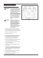
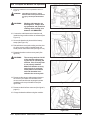
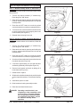
Procedures For Transporting
How to Put the Machine Into a Van or Truck
WARNING:
This machine is heavy. Get
assistance before attempting
to transport or move it. Use
two able persons to move the
machine on a ramp or
incline. Always move slowly.
Do not turn the machine on a
ramp. Do not stop and leave
the machine on a ramp or
incline. The loading ramp
must be a minimum of 32"
wide.
WARNING:
Machines can topple over if
guided over the edges of
stairs or loading docks and
cause injury or damage.
Stop and leave this machine
only on a level surface.
When you stop the machine,
put all switches into their
"OFF" position.
Figure #1
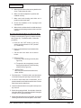
1. Make sure the loading ramp is at least eight
(8) feet (2.5m) long and a minimum of 32" (0.8m)
wide, and strong enough to support the machine.
2. Make sure the ramp is clean and dry.
3. Put the ramp in position.
4. Remove squeegee assembly, brush housing and
brush or pad driver before loading. Clarke
recommends that both the solution tank and
recovery tank are empty before loading.
5. On the L17/L20 models only, turn the key switch
"ON" and press the green "ON" button.
6. Align the machine on a level surface five (5) feet
(2 m) in front of the ramp.
7. Put the traverse knob at full speed (on L17/L20
models only).
8. For the L17/L20 machines, push in either one of
the forward/reverse switches while pushing in the
white reverse switch. Back the machine up the
ramp. See figure 1.
9. For the S17/S20 machines, push the machine
backwards to the top of the ramp.
10. Switch machine "OFF", and on the L17/L20
models, turn key switch "OFF".
Page
-8-
Clarke® Operator's Manual -FOCUS S17/L17 and S20/L20
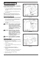
Procedures For Transporting (cont.)
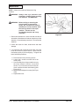
11. Fasten the machine to the vehicle. Clarke
recommends a strap over the top of the
machine and a strap to keep the machine from
rolling forward or backwards. If this is not done,
there is a possibility of the machine toppling
over. Three tie down points are provided on the
steel frame of the machine, for securing
machine (see figure 2a).
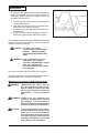
How to Remove the Machine From a Van or
Truck
1. Make sure there are no obstructions in the area.
2. Make sure the unloading ramp is at least eight
(8) feet (2.5m) long and a minimum of 32"
(0.8m) wide, and strong enough to support the
machine.
Figure #2
3. Make sure the ramp is clean and dry.
4. Put the ramp in position.
5. Unfasten the machine.
WARNING:
The machine is heavy.
Make sure you use two able
persons to assist in moving
the machine down the
ramp.
6. On S17/S20 models, get two people to pull
machine off ramp. It is recommended that the
"S" model be unloaded in the forward position.
7. On the L17/L20 models only, turn the key
switch "ON" and press the green "ON" button.
8. Set the traverse center knob to the slowest
forward speed setting. Carefully and slowly,
drive the machine to the top of the ramp and
start down (L17/L20 models only).
Tie Down Point
(both sides of
machine)
Tie Down Point
Figure #2a
9. While pushing in the right or left forward switch
the machine will go forward (L17/L20 models
only). See figure 2.
10. As the machine begins to travel down the ramp,
push in the forward switch to maintain a slow
downward speed (L17/L20 models only).
11. Replace squeegee assembly, brush housing,
and brush or pad driver after machine is
unloaded and ready to use.
Clarke® Operator's Manual
-FOCUS S17/L17 and S20/L20
Page -9-
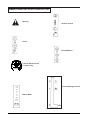
SYMBOLS USED ON FOCUS S17/S20 & L17/L20
+
Warning
Solution Control
Power
Brush Up/Down
Traverse Speed Control
("L Class" only)
Vacuum/Squeegee Control
Battery Meter
Page
-10-
Clarke® Operator's Manual -FOCUS S17/L17 and S20/L20
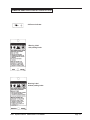
SYMBOLS USED ON FOCUS S17/S20 & L17/L20
AC Power Indicator
Warning Label
with parking brake
Warning Label
without parking brake
Clarke® Operator's Manual
-FOCUS S17/L17 and S20/L20
Page -11-
Machine Control Panel
Electrical Power Indicator (See Figure 3, Item "A")
A yellow light will be illuminated when the charger is
plugged into an AC electrical outlet. The electrical cord
must be unplugged and stowed before operating the
machine.
Reverse Switch (See Figure 3, Item "H")
On Traverse "L" Models Only - The reverse switch,
when used in conjunction with one of the forward/reverse
switches, causes the machine to reverse directions. The
reverse speed is 70% of the forward speed.
Key Switch (See Figure 3, Item "B")
The key switch is standard on the "L" models. It is used
primarily for preventing unauthorized use by removing
the key. To turn the control panel "ON", the key switch
must be turned clockwise and then the green "ON"
button must be pressed (see item "C"). To turn the
control panel "OFF", turn the key switch counterclockwise.
Brush Motor Buttons (See Figure 3, Item "I")
To lower brush head and activate brush motor(s) and
solution flow, press and hold the down button until the
green light is illuminated. Continue to press and hold
down button for additional brush pressure, or until brush
head stops. The brush motor(s) and solution will then
operate when either one or both of the forward/reverse
button(s) are pressed. To deactivate the brush motor(s)
and solution flow, raise the brush head by pressing and
holding the up button until the green indicator light turns
off.
ON/OFF Buttons (See Figure 3, Item "C")
Pressing the green button turns "ON" the power to the
control panel (if the machine is equipped with a key
switch, first turn the key clockwise). Pressing the red
button turns "OFF" power to the control panel (if the
machine is equipped with a key switch, the power can
also be turned "OFF" by turning the key counterclockwise.)
NOTE: The "L model" machine is equipped with self
diagnostics and will sometimes fail to operate if a fault
is detected. Once the fault is corrected the machine can
be reset by turning the power "OFF" and turning it back
"ON". If this fails to correct the problem, contact your
authorized service personnel immediately.
NOTE: This machine is equipped with a battery power
saving device. If the machine is unattended for more
than 16 minutes, it will automatically shut itself off.
Battery Meter (See Figure 3, Item "D")
The battery meter indicates the relative charge of the
battery pack. The meter has two green, one yellow and
one red light. When the light switches to "red" the
brush(es) and solution flow will stop. All other functions
will continue to operate. The batteries must then be
immediately recharged to prevent shortening the life of
the battery pack.
Solution Control Buttons (See Figure 3, Item "J")
The solution control buttons regulates the flow of chemical solution to the floor. When powering up the machine,
the solution setting will automatically adjust to the mid
setting (see your authorized Clarke serviceman if a
different setting is preferred). To increase the flow, press
and hold or press the upper button (+) multiple times.
The green bar will move up the scale as the flow increases. To decrease the flow, press and hold or press
the lower button (-) multiple times. The green bar will
move down the scale as the flow decreases. When the
bar reaches the lowest setting the solution flow is turned
"OFF". NOTE: The solution will only flow when the
brush head is down and in the operating position.
Vacuum Motor Switch (See Figure 3, Item "K")
To activate the vacuum motor, lower the squeegee
handle. The handle has three positions. Lowest position
is the operating water pickup position. The center
position is used during transport to clear vacuum hose.
The upper position is the vacuum motor "OFF" position.
G
Control Handles (See Figure 3, Item "E")
The control handles are located at the rear of the
machine. They are used to guide the machine.
Traverse Speed Knob (See Figure 3, Item "F")
To increase speed, turn knob clockwise. The machine
will not traverse when the knob is turned fully counterclockwise.
Forward/Reverse Switch (See Figure 3, Item "G")
On Traverse "L" Models Only - The forward/reverse
switch starts the traverse motor forward and when the
brush head is in the down or scrub position it also
activates the brush motor(s) and solution flow. There is
a two second delay for the brush motor(s) to stop after
releasing the switch. Either the right or the left switch
can be used. Use either switch in conjunction with the
white reverse switch to reverse the traverse motor.
"S" Model - On the non-traverse models these
switches activate the brush motor(s) and solution flow
when the brush head is in the down or scrub position.
Page
-12-
F
H
J
K
G
E
A
E
C
D
I
L M N 0 P Q
B
Figure 3
Clarke® Operator's Manual -FOCUS S17/L17 and S20/L20
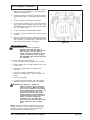
Machine Control Panel
Circuit Breakers (Figure 3, Items "L", "M", "N",
"O", "P" & "Q"
The circuit breaker reset buttons are located on the
lower control handle. The breakers are located as
follows:
Item "L" - Control Circuits (5 amps)
Item "M" - Control Module and Head Actuator (5 amps)
Item "N" - Vacuum Motor (25 amps)
Item "O" - Rotary Brush Motor (40 amps) or
Cylindrical Brush Motor (25 amps)
Item "P" - Cylindrical Brush Motor (25 amps)
Item "Q" - Traverse Motor (25 amps) (L17/L20 Only)
Figure 4
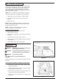
Machine Controls and Features
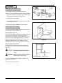
Squeegee Lift Handle, See Figures 4 and 5
The squeegee lift handle is located in the control
handle. It is used to raise or lower the squeegee. The
vacuum motor is turned on when the handle is lowered
to either the center or lowest position.
Float Shut Off, See Figure 6
The shut-off switch for the vacuum motor is located in
the recovery tank. It automatically turns off the
vacuum motor when the recovery tank is full. NOTE: If
excessive foaming occurs in recovery tank,
defoamer must be added. Damage to vacuum
motor could result from foam entering into the
vacuum motor.
Parking Brake (Optional)
NOTE: Parking Brake must be used if operating
machine on surfaces with greater than 2% gradient.
The parking brake prevents movement of the machine.
Figure 5
CAUTION: Do not activate the parking brake
while the machine is moving.
The brake is located to the right hand rear of the
machine. Press pedal to activate brake and lift pedal
to disengage brake.
Figure 6
Clarke® Operator's Manual
-FOCUS S17/L17 and S20/L20
Page -13-
How To Prepare the Machine For Operation
The FOCUS 17/20 machines use two 12-volt batteries.
The batteries are located in the battery compartment
under the recovery tank. It is recommended to remove
the recovery tank when installing the batteries.
How To Install The Batteries
To install the batteries, follow this procedure:
1. Turn the machine off. Set brake (if equipped).
2. Make sure the recovery tank is empty. NOTE:
The recovery tank on the FOCUS 17/20 is
designed for easy removal and cleaning.
Figure 7
3. Disconnect the hoses from the recovery lid (See
Figure 7.)
4. Unhook the recovery tank drain hose valve from
it's hanger bracket and lay the loose end on the
floor (See figure 8.)
WARNING: Before raising or removing the
recovery tank, be sure tank is
empty. Do not operate or perform maintenance on the machine while the recovery tank is
in the open position. The tank
can be accidentally bumped and
it may slam shut.
Figure 8
5. Disconnect the blue electrical float connector
(See Figure 9).
6. Unhook the tether clip from the recovery tank
(See Figure 10).
7. Unlatch and stow prop rod back in solution tank
and close recovery tank.
8. While pushing the tank to the rear, carefully lift
and remove recovery tank from the machine.
Leave the recovery drain hose attached to the
recovery tank.
Figure 9
Figure 10
Page
-14-
Clarke® Operator's Manual -FOCUS S17/L17 and S20/L20
How To Prepare the Machine For Operation
Place the batteries in the compartment shown in
Figure 11.
WARNING:
WARNING:
-
+
The batteries are heavy. Lifting
batteries without help could result in
an injury. Get help to lift the batteries.
Working with batteries can
be dangerous. Always wear
eye protection and protective
clothing when working near
batteries. NO SMOKING!
FRONT
9.
+
-
Figure 11
10. Connect the cable between the batteries and
install the long machine cables as indicated (See
Figure 11).
11. Secure the batteries in place with the battery
straps (See Figure 12).
12. Reinstall the recovery tank making sure the pivot
pin in the recovery tank is installed under the
metal plate on the solution tank (See figure 13A.)
13. Reattach the tether to the recovery tank (See
figure 10).
WARNING:
The recovery tank can fall off
of the machine when opening the tank or operating the
machine, if the recovery tank
is not properly installed.
Make sure that the recovery
tank pivot pin is under the
metal plate on the solution
tank and the tether is attached to the recovery tank.
14. Reconnect the vacuum and squeegee hoses to
the recovery lid. Make sure the hose to the
vacuum motor and the rear squeegee hose are
installed over the top of the drain hose (See
figure 13B).
Figure 12
Figure 13A
15. Reconnect the blue float connector (See figure 9,
page 12).
16. Charge the batteries before using the machine.
Figure 13B
Clarke® Operator's Manual
-FOCUS S17/L17 and S20/L20
Page -15-
How To Prepare the Machine For Operation
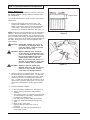
Battery Maintenance
The electrical power to operate the machine comes from
the storage batteries. Storage batteries need preventative maintenance.
Correct Level
To maintain the batteries in good condition, follow these
instructions.
1.
Keep the electrolyte at the correct level. The
correct level is between 1/4" (1/2 cm) below the
bottom of the tube in each cell and above the tops
of the plates. Check the level of the electrolyte
each time you charge the batteries. See figure 14.
NOTE: Check the level of electrolyte prior to charging the
batteries. Be sure the plates in each cell are covered
with electrolyte before charging. Do not top off the cells
prior to charging the battery. Electrolyte expands during
charging. As a result, the electrolyte could overflow from
the cells. Always top off the cells with distilled water
after charging.
Figure 14
CAUTION: Irreversible damage will occur to
the batteries if electrolyte does not
cover the plates. Keep the electrolyte at the correct level.
CAUTION: Machine damage and discharge
across the tops of the batteries can
occur if the batteries are over filled.
Do not fill the batteries up to the
bottom of the tube in each cell.
Wipe any acid from the machine or
the tops of the batteries. Never add
acid to a battery after installation.
Figure 15
CAUTION: Batteries must be refilled with
distilled water only. Do not use tap
water as it may contain contaminants that will damage batteries.
2. Keep the tops of the batteries clean and dry. Keep
the terminals and connectors clean. To clean the
top of the batteries, use a damp cloth with a weak
solution of ammonia or bicarbonate of soda solution. To clean the terminals and connectors, use a
terminal and connector cleaning tool. Do not allow
ammonia or bicarbonate of soda to get into batteries.
3.
Keep the batteries charged.
4.
To drain the battery compartment: See Figure 15.
a. Always wear eye protection and protective
clothing.
b. Add a weak solution of ammonia or bicarbonate
of soda solution to the battery compartment to
neutralize any spilled acid.
c. Pull drain hose out from under the transaxle.
d. Place your hand behind flange and open the
valve.
e. When empty, close valve.
f. Replace valve and drain hose on top of
transaxle.
g. Neutralize any acid spills with ammonia or
bicarbonate of soda.
Page
-16-
Clarke® Operator's Manual -FOCUS S17/L17 and S20/L20
How To Prepare the Machine For Operation
How To Charge The Batteries
WARNING: Charging the batteries in an area
without adequate ventilation could
result in an explosion. To prevent
an explosion, charge the batteries
only in an area with good
ventilation.
WARNING: Lead acid batteries generate gases
which could explode. Keep sparks
and flames away from batteries. NO
SMOKING!
To charge the batteries, follow this procedure:
Figure 16
1. Place the machine on a flat-level surface with
adequate ventilation.
2. Set the parking brake if one is provided.
3. Remove power to the control panel by pressing the
red "OFF" button. If the machine is equipped with
a key switch, turn the key counterclockwise to the
"OFF" position.
4. Before charging the batteries, the battery
compartment needs to be vented. To vent the
compartment, the recovery tank needs to be
propped open.
WARNING: Before raising or removing the
recovery tank, be sure tank is
empty. Do not operate or perform
maintenance on the machine while
the recovery tank is in the open
position. The tank can be
accidentally bumped and it may
slam shut.
Figure 17
5. The FOCUS 17/20 is equipped with an on-board
charger located behind the recovery tank (See
Figure 17). The charger is a 3-stage charger
designed to maximize battery life. The AC power
cord to the on-board charger is located in its
storage compartment under the control handle at
the rear of the machine (See Figure 16). Pull the
cord out of the storage compartment.
6. Connect the charger to a properly grounded single
phase (3-wire) wall receptacle. NOTE: When the
charger is plugged into the wall receptacle, the
yellow light will be illuminated on the control panel
next to the plug symbol and the charger with begin
charging (see figure 3, item A).
3-Stage Charging Sequence:
• Bulk Stage - In the bulk stage of charging, the
red light is illuminated on the charger (See
Figure 17). During this stage the charger is
supplying its full amp output to the batteries. It
will continue to charge the batteries at this rate
until the batteries reach approximately 75% of
their capacity.
Clarke® Operator's Manual
-FOCUS S17/L17 and S20/L20
Page -17-
How To Prepare the Machine For Operation
• Absorption Stage - In the absorption stage the red
and green light will be illuminated on the charger
(See Figure 17). During this stage the charger
maintains constant voltage and lets the batteries
absorb the charge at their own rate.
• Float and Maintenance Stage - In the maintenance stage the red light turns off and only the
green light will be illuminated on the charger (See
Figure 17. During this stage the charger applies a
lower, closely regulated voltage to maintain full
charge and prevents discharge. Batteries can be
connected indefinitely without harm.
Figure 18
8. Unplug charger power cord from the wall outlet before
powering up control panel on machine. Store the
charger power cord in the storage compartment
located under the control handle (See Figure 16).
9. Unlatch and stow prop rod back in solution tank and
close recovery tank after charging has been completed.
NOTE: It is not necessary to remove the brush housing assembly
when removing or installing the brush or pad driver. For greater
access to the brush or when driving the machine up a ramp, the
brush housing assembly can be removed. To remove brush
housing assembly, pull outward on the spring loaded pin on the
left side of the housing, then lift the brush housing assembly up
and outward (See Figure 18). Reinstall the brush housing
assembly in reverse order, making sure the cross bar in the
brush housing is inserted into the two slots located in the motor
mount and the spring loaded pin is locked into position (See
Figure 19).
Figure 19
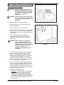
How To Install Rotary Brush or Pad Driver (if equipped)
To install the brushes or pad drivers on the machine, follow this
procedure:
1.
Turn the key switch clockwise ("L" models only). Press the
green "ON" button.
2.
Raise the brush head by pressing and holding the brush
up switch until brush head is in it's full up and rotated
position (See Figure 20).
3.
Press the red "OFF" button or turn the key switch counterclockwise on machines equipped with key.
4.
Put a brush or pad driver under the brush motor plate and
align the lugs on the motor with the slots on the brush
gimbal.
5.
Push the brush up and rotate counter direction to scrub
rotation, until lugs lock (See Figure 20).
6.
Reinstall brush housing if removed.
DANGER:
Page
-18-
Figure 20
Operating a machine that is not completely
or fully assembled could result in injury or
property damage. Do not operate this
machine unless it is completely assembled.
Inspect the machine carefully before
operation.
Clarke® Operator's Manual -FOCUS S17/L17 and S20/L20
How To Prepare the Machine For Operation
How To Remove Rotary Brush or Pad Driver (if
equipped)
To remove the brush or pad driver from the machine, follow
this procedure:
1. Turn the key switch clockwise ("L" models only).
Press the green "ON" button.
2. Raise the brush head by pressing and holding the
brush up switch until brush head is in it's full up and
rotated position.
3. Press the red "OFF" button or turn the key switch
counterclockwise on machines equipped with key.
4
To remove brush, rotate brush in the same direction
to scrub rotation with a quick snapping action until
brush releases (See Figure 21).
Figure 21
5. Reinstall brush housing if removed.
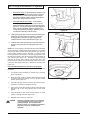
How To Change Or Rotate Cylindrical Brushes (if
equipped)
To install or rotate brushes on the machine, follow this
procedure:
1. Turn the key switch clockwise ("L" models only).
Press the green "ON" button.
2. Raise the brush head by pressing and holding the
brush up switch until brush head is in it's full up and
rotated position.
Figure 22
3. Press the red "OFF" button or turn the key switch
counterclockwise on machines equipped with key.
4
Go to front of the machine and remove thumb screw
from brush door (See Figure 22).
5. Lower door approximately 1/2 inch and slide door
and bearing assembly off shaft (See Figure 23).
6. Remove brush spacer and brush by sliding off of
brush shaft (See Figure 24).
7. Rotate brush or replace.
8. Slide brush on shaft and rotate slowly until drive pins
are lined up with brush slots. Push brush all the way
in.
Figure 23
9. Install brush spacer on shaft.
10. Slide brush door bearing assembly on shaft.
11. Raise door and install thumb screw.
DANGER: Operating a machine that is not
completely or fully assembled could
result in injury or property damage.
Do not operate this machine unless
it is completely assembled. Inspect
the machine carefully before
operation.
Clarke® Operator's Manual
-FOCUS S17/L17 and S20/L20
Figure 24
Page -19-
How To Operate The Machine
How To Operate The Squeegee
The squeegee wipes the floor while the vacuum motor
removes the dirty solution from the floor. Use your hand
to lower or raise the squeegee handle. To operate the
squeegee, follow this procedure:
1. To lower the squeegee and start the vacuum motor,
move the squeegee lever to the right and down (See
figure 25).
2. To raise the squeegee, lift the squeegee lever up
(See figure 26.)
NOTE: The center position lets the vacuum motor
continue to run with the squeegee off the floor to avoid
drips and also allows you to back up the machine.
How To Fill The Solution Tank
The solution tank is filled at the rear of the machine (See
figure 27). To fill the solution tank follow this procedure:
Figure 25
1. Add a cleaning chemical to the solution tank. For
the correct amount of chemical, follow the directions shown on the container.
2.
Remove the solution lid and fill the solution tank
with water.
WARNING: Water solutions or cleaning materials used with this type of machine
can leave wet areas on the floor
surface. These areas can cause a
dangerous condition for the operator
or other persons. Always put
CAUTION signs near the area you
are cleaning.
WARNING: Machines can ignite flammable
materials and vapors. Do not use
with or near flammables such as
gasoline, grain dust, solvents and
thinners. Use only a commercially
available cleaners and
concentrations intended for floor
scrubbing applications.
Figure 26
WARNING: Clarke recommends a maximum
water temperature of 120oF (49oC).
Operating The Machine
NOTE: Put the machine in the lowest traverse speed
setting. Use the machine in an area that has no furniture
or objects until you can do the following:
1. Move the machine in a straight direction, forward and
backward.
2. Stop the machine safely.
3. Turn the machine both left and right and return to a
straight direction.
Figure 27
To move the machine, follow this procedure:
1. Release the parking brake (if equipped with
machine).
2. Turn the key switch clockwise to the "ON" position (on
"L" models only). Press the green "ON" button.
3. Raise the brush to the highest setting.
4. Raise the squeegee.
Page
-20-
Clarke® Operator's Manual -FOCUS S17/L17 and S20/L20
How To Operate The Machine
5. When either the left or right forward/reverse switches
(figure 28, item A) are pushed in, the machine will go
forward ("L" models only).
6. Control the speed of traverse by using the traverse
speed control knob ("L" models only) (figure 28, Item
C).
B
C
A
A
7. To stop, release the forward/reverse switch.
8. To reverse the machine, push in the white reverse
switch (figure 28 item B) and either the right or left
forward/reverse switch (figure 28 item A) at the same
time ("L" models only).
9.
To stop, release the forward/reverse switch.
10. To turn the machine, push the rear of the machine to
the side.
11. When you stop the machine, press the red "OFF"
button or turn the key switch counterclockwise to the
"OFF" position ("L" models only). Remove the key
and set the parking brake (if equipped).
Figure 28
How To Clean A Floor
WARNING: Water solutions or cleaning
materials used with this type of
machine can leave wet areas on the
floor surfaces. These areas can
cause a dangerous condition for the
operator or other persons. Always
put CAUTION signs near the area you
are cleaning.
To clean a floor follow this procedure:
1. Set the parking brake (if equipped with machine.)
2. Put the water and a cleaning chemical in the clean
solution tank.
3. Release the parking brake (if equipped with
machine.)
4. Turn the key switch clockwise to the "ON"
position ("L" models only). Press the green "ON"
button.
5. Lower the squeegee.
6. Press the brush down button until yellow light is
illuminated and the correct pressure is achieved.
WARNING: This machine is capable of
maximum head pressure with worn
pads or brushes. With this feature,
there is the possibility of exceeding
the recommended brush pressure on
new pads or brushes. This will
either create re-occurring circuit
breaker tripping or the possibility of
lost traction and control. The brush
switch should be activated to
accomplish only enough brush
pressure for the job. This will allow
longer battery life and cleaning
time.
NOTE: Keep the machine moving when the brush is
rotating on the floor. Pre-wet brush/pad or keep light
pressure on brush until solution flow is adequate to
keep brush/pad from scratching the floor.
Clarke® Operator's Manual
-FOCUS S17/L17 and S20/L20
Page -21-
How To Operate The Machine
To pre-wet brushes you should first turn the speed knob to
the lowest traverse setting on the "L" model. Then on both
the "S" and "L" models, lower brushes until brushes are
just touching the floor and the yellow light on the control
panel in illuminated. Activate the forward/reverse switch to
start motor and solution flow.
NOTE: On the "L" model, the machine will not move when
the traverse speed knob is rotated fully counterclockwise.
7. Adjust the flow of clean solution to the flow desired.
8. Move the machine across the floor in the forward
direction.
9. Make a 180° turn.
NOTE: When you make more passes across the floor, let
the brush clean approximately 2 inches (5 cm) of the area
already cleaned by the brush.
NOTE: During most cleaning procedures, apply and
remove the solution in one operation.
How To Clean A Very Dirty Floor
To clean a very dirty floor, follow this procedure:
1. Apply solution to the floor.
2.
Do not lower the squeegee. This will keep the vacuum
motor off.
3.
Lower the brush or pad and scrub the floor.
4.
Scrub the floor again with additional solution and lower
the squeegee.
5.
Pick up all the solution with the squeegee.
Maintenance
WARNING:
Maintenance and repairs must be done by
authorized personnel only.
WARNING:
Always empty the solution tank and recovery tank before doing any maintenance.
WARNING:
Keep all fasteners tight.
These Maintenance Procedures Must Be Done
Every Day
Figure 29
Keep the machine clean, it will need fewer repairs and have
longer life.
Do These Procedures When You Begin Your Work Period
1.
Disconnect AC power from battery charger (follow
charger instructions).
2.
Store AC power cord to charger in machine storage
compartment (See Figure 29).
3.
Make sure the screen filter is installed properly in the
recovery lid and is clean (See figure 30).
4.
Make sure the recovery tank lid is on correctly (See
Figure 30).
Figure 30
Page
-22-
Clarke® Operator's Manual -FOCUS S17/L17 and S20/L20
Maintenance
5. Make sure the valve on the recovery drain hose is
clean. Tightly close the valve.
6. Make sure the brush/pad is in position and
installed correctly.
7. Make sure brush housing and skirts are in
position on the brush head.
8. Check the installation of the squeegee and
squeegee hose.
9. Make sure the solution drain / level indicator hose
is secure on the storage mount on the rear of the
machine.
Figure 31
Do These Procedures When You End Your Work
1. Drain the solution tank (Figure 31) and the recovery
tank (Figure 32). To drain the tanks , follow this
procedure:
a. Press the red "OFF" button or turn key
switch counterclockwise to "OFF" position
("L" model only).
b. Remove the drain hose from the back of the
machine.
c. Put the end of the hose over a drain or
bucket.
Figure 32
d. Recovery Tank:
1.) Turn the valve housing to the left (See
Figure 33).
2.) To open the valve completely, turn the
housing fully to the left. Pull the housing
off of the valve (Figure 34).
e. Solution Tank:
When hose is lowered below water level,
water will flow.
2. Flush the tanks. To flush the tanks, put clean water
in the tank through the opening on top of the tank.
Figure 33
3. If a tank or drain hose has an obstruction, use a
pressure water hose to flush the tank or hose. Put the
water hose into the drain hose.
4. Leave the tanks and the recovery drain valve open to
dry in the air.
5. Check the squeegee blade. Use a cloth to clean the
squeegee blade. If the squeegee blade is damaged
or worn, turn or replace the blade.
6. Check and clean the recovery lid gasket. Use a mild
cleaning solution and rinse the parts in clean water.
Figure 34
Clarke® Operator's Manual
-FOCUS S17/L17 and S20/L20
Page -23-
Maintenance
7. On machines with cylindrical brush head, the debris tray
needs to be emptied regularly to prevent overflow. To
remove the debris tray from the machine follow this
procedure (See Figure 35).
a. Go to the left side of the machine, to the rear of the
cylindrical brush head.
b. Grab the end of the tray with the left hand and the
center of the tray with the right hand.
c. Lift center of tray with right hand and slide tray out
with left hand.
d. Empty tray and clean before sliding tray back in.
Make sure upper and lower slides are engaged.
Figure 35
Check the batteries and if necessary add distilled water after
charging. The correct level is within 1/4 inch (1/2 cm) of the
bottom of the tube in each cell.
CAUTION: Tap water may contain
contaminants that will damage
batteries. Batteries must be
refilled with DISTILLED WATER
ONLY.
WARNING: Lead acid batteries generate
gases which can cause an
explosion. NO SMOKING. Always
wear eye protection and
protective clothing when working
near batteries.
Use a clean cloth and wipe the surface of the machine.
Charge the batteries. See the instructions in the section of
this book called “How To Charge The Batteries”.
Maintenance Procedures To Be Done Every Week:
WARNING:
Maintenance and repairs must be
done by authorized personnel only.
Always empty the solution tank and
the recovery tank before doing any
maintenance. Keep all fasteners
tight.
WARNING: Always wear eye protection and
protective clothing when working
near batteries. Do not put tools or
other metal objects across the battery
terminals or the tops of the batteries.
CAUTION:
Page
-24-
To prevent damage to the machine,
and discharge across the tops of the
batteries, do not fill the batteries
above the bottom of the tube in each
cell. Wipe any acid from the machine
or the tops of the batteries. Do not add
acid to battery after installation.
Clarke® Operator's Manual -FOCUS S17/L17 and S20/L20
Maintenance
NOTE: Always turn machine off before servicing
machine.
WARNING: Always wear eye protection and
protective clothing when working
near batteries. NO SMOKING!
WARNING: Before raising or removing the
recovery tank, be sure tank is
empty. Do not operate or perform
maintenance on the machine while
the recovery tank is in the open
position. The tank can be
accidentally bumped and it may
slam shut.
A
B
Figure 36
1. Disconnect the batteries. Use a cloth and a solution of
ammonia or bicarbonate of soda to wipe the top of the
batteries. Clean the battery terminals. Reconnect the
batteries.
2. Check the hoses for leaks, obstructions and other
damage.
3. On machines with cylindrical brush head, check the
brush drive belts for proper tension. Belts must be
tensioned properly to prevent slipping. To tighten the
belts, follow this procedure:
a. Remove belt cover by removing screws.
b. Loosen the 2 screws on either side of the
motor pulley.
c. Use a small pry bar or large screwdriver to pry
the motor upward to achieve correct belt
tension. Pry on the motor close to where the
motor contacts the brush head casting (See
Figure 36, A).
d. Hold tension and tighten 2 screws (See Figure
36,B).
e. Replace belt cover.
Clarke® Operator's Manual
-FOCUS S17/L17 and S20/L20
Page -25-
Maintenance
Maintenance For The Squeegee
To remove the squeegee, follow this procedure:
1. Remove the squeegee assembly by loosening the two
knobs that attach the squeegee to the machine. Pull
the squeegee assembly off (See figure 37).
2. Inspect the squeegee blade.
Figure 37
3. If the blade is worn, turn the blade so that a new edge
is in the wiping position.
4. Reinstall squeegee assembly on the machine.
How To Adjust The Squeegee
The following adjustments are set at the factory, however
they may require slight adjustment.
Adjusting Squeegee Tilt:
The tilt of the squeegee causes the rear blade to raise up
in the center or on the ends, depending on which
direction the tilt is changed. For tilt adjustment, refer to
figure 38. Loosen left and right screw "X". In order to
bring the blades down in the center, tip "Y" down. To
bring both ends down, tip "Y" up. Make very small
adjustments and try it until a uniform flare is achieved.
Figure 38
Adjusting Squeegee Blades:
When properly installed the front blade should be approximately 0.06" (1.5mm) above the rear blade (See
figure 39).
WARNING: Maintenance and repairs must be
done by authorized personnel
only .
WARNING: Electrical repairs must be done by
authorized personnel only.
Consult your Clarke Authorized Service Person to do
the service procedures.
REAR BLADE
0.06 (1.5 mm)
Figure 39
Use only genuine Clarke parts.
Page
-26-
Clarke® Operator's Manual -FOCUS S17/L17 and S20/L20
Clarke
FOCUS 17/20
Accessories
ACCESSORIES
Description
Clarke Care Kit
29" Squeegee Assembly
32" Squeegee Assembly
Poly Dur Protectant
Hour Meter Kit
Key Switch Kit
Parking Brake Kit
Vacuum Muffler Kit
Power Wand Kit
Urethane Caster Assembly
Dual Direct Clutch Plate
Center Lock Pad Retainer
Squeegee Hose "S" Trap
Rotary Disk Brushes and Pad Assemblies:
Description
17" Part No.
Pad Driver Asm.
10405A
Polypropylene
52539A
Nylon
52540A
Lite Grit
52543A
Clean Grit
52541A
Part No.
14607A
18820A
10129A
50478A
10656A
10490A
10491A
10492A
10489A
61290A
30034A
56941A
30482A
20" Part No.
30629A
30630A
30631A
30632A
30633A
Cylindrical Brushes
Size
Description
4"
Polypropylene
4"
Nylon
4"
Clean Grit
4"
Super Grit
Part No.
30231A
30232A
30233A
30234A
29" Squeegee Blades
Description
Blade, Rear - Gum Rubber
Blade, Rear - Nitrile Solid
Blade, Front - Ribbed Urethane
Blade, Front - Notched Neoprene
Part No.
30931A
30938A
30951A
30930A
32" Squeegee Blades
Description
Blade, Rear - Gum Rubber
Blade, Rear - Nitrile Solid
Blade, Rear - Ribbed Orange
Blade, Front - Ribbed Natural
Blade, Front - Slit Grout
Blade, Front - Ribbed Orange
Part No.
30067A
30081A
30085A
30066A
30079A
30083A
Clarke® Operator's Manual
-FOCUS S17/L17 and S20/L20
Page -27-
NOTES
Page
-28-
Clarke® Operator's Manual -FOCUS S17/L17 and S20/L20
S17/L17 Rotary
S17/L17 Cylindrical
S20/L20 Rotary
Section II
Parts and Service Manual
(70899A)
U.S. Patent No. 6,105,192; No. 6,557,207; No. 6,760,947 and other Patents Pending
Clarke® Operator's Manual
-FOCUS S17/L17 and S20/L20
Page -29-
HOW TO CORRECT PROBLEMS IN THE MACHINE
PROBLEM
There is no solution flow.
The solution flow does not stop.
The machine does not remove all the
water from the floor.
The batteries do not give the normal
running time.
Page
-30-
CAUSE
ACTION
The solution tank is empty.
Fill the solution tank.
There is an obstruction in the solution hose
or filter.
Remove the obstruction from the hose or filter.
The solution valve or electric wiring is
damaged.
Repair or replace the valve or the electric
wiring.
The control module is defective.
Replace control module
The solution valve is open.
Close or Clean the solution valve.
The solution valve or wiring is damaged.
Repair or replace the valve and the wiring.
The solution valve is dirty
Clean the solution valve.
There is a damaged seat and washer in the
solution valve.
Replace the seat and washer.
The control module is defective.
Replace control module.
The squeegee is up.
Lower the squeegee.
The squeegee tilt is not correct.
To adjust, see the section titled "How to Adjust
the Squeegee".
The recovery tank is full.
Drain the recovery tank.
The screen filter is dirty.
Clean the screen filter.
There is an obstruction or damage in the
squeegee or squeegee hose.
Remove the obstruction or repair the damage.
The vacuum motor is not running.
Check for tripped breaker. Have an authorized
service person make repairs.
The squeegee hose is disconnected, or
damaged
Check and connect hose.
The squeegee blade is damaged, worn, or
incorrectly installed.
Turn or replace the squeegee blade.
Correctly install the squeegee blade.
The gaskets on the cover of the recovery
tank are damaged.
Replace the gaskets.
The battery terminals are dirty or damaged.
Clean the terminals and connectors. Replace
the damaged cables. Charge the batteries.
The electrolyte level is too low.
Add distilled water to each cell and charge the
batteries.
The batteries are not fully charged.
Charge the batteries for a full 16 hour charge.
The charger is damaged.
Have an authorized service person repair the
charger.
The battery is defective.
Check voltage of each cell while discharging.
The batteries are disconnected.
Connect the batteries.
Brush is in heavy scrub setting.
Adjust Pressure.
Clarke® Operator's Manual -FOCUS S17/L17 and S20/L20
PROBLEM
The cleaning is not even.
CAUSE
ACTION
The scrub brush or pad is worn.
Replace the scrub brush or pad.
There is damage to the brush assembly,
caster or the solution valve.
The brush motor is not running
Have an authorized service person make
the needed repairs.
Check for tripped breaker. Reset. Check
for loose connections.
The solution level is low.
Fill the solution tank.
NOTE: If the problem continues consult an
authorized service person.
The machine does not run.
Clarke® Operator's Manual
The machine loses power.
Reset the circuit breaker.
Key or switch is off.
Turn key or switch on.
Batteries are disconnected.
Battery terminals are dirty.
Check the battery connections.
Batteries are discharged
Check battery meter and recharge
NOTE: If the problem continues consult an
authorized service person.
-FOCUS S17/L17 and S20/L20
Page -31-
Clarke®
FOCUS S17/20, L17/20 and L17 Cyl.
Final Assembly 1/05
1
2
14
3
12
13
4
5
12
12
2
16
3
15
3
6
2
11
7
2
8
9
10
Page
-32-
Clarke® Operator's Manual -FOCUS S17/L17 and S20/L20
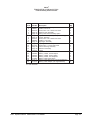
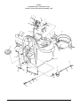
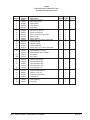
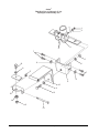
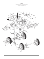
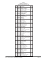
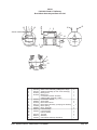
Clarke®
FOCUS S17/20, L17/20 and L17 Cyl.
Final Assembly Parts List 1/05
Ref. #
1
2
3
4
5
6
7
8
9
10
11
12
13
14
15
16
NI
NI
NI
NI
NI
NI
Part No.
Page 32
980651
80212A
Page 34
Page 48
Page 46
Page 44
80197A
980652
Page 42
Page 40
80179A
Page 38
Page 36
30334A
52570A
40606A
40605A
40070A
41206A
41217A
61337A
Description
Recovery Tank Assembly
Washer, Flat 5/16"
Screw, M8 x 1.25 x 35mm Hex Head
Solution Tank Assembly
Rotary Disk Head Assembly Option
Cyl. Head Asm. Option (L17 Cyl. model only)
Frame Assembly
Screw, M8 x 1.25 x 20mm Hex Head
Washer, Lock 5/16"
Squeegee Assembly
Squeegee Lift Assembly
Screw, M6 x 1 x 15mm Pan Head
Control Housing Assembly
Electrical Assembly
Tether
Clip, Tether
Battery, 130AH, 12V Wet Option
Battery, 130AH, 12V Dry Option
Battery, 100AH, 12V Gel Option
Battery Cable (Taper Style)
Battery Cable (Ring Style) (use w/gel batteries)
Battery Cable Adapter (use w/gel batteries)
Qty
1
8
4
1
1
1
1
4
4
1
1
6
1
1
1
1
2
2
2
1
1
2
NI = Not Illustrated
Clarke® Operator's Manual
-FOCUS S17/L17 and S20/L20
Page -33-
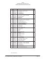
Clarke®
FOCUS S17/20, L17/20 and L17 Cyl.
Recovery Tank Assembly 1/05
1
2
27
30
3
28
29
4
5
14
8
15
6
14
9
6B 6C
6A
7
10
26
17
16
11
24
12
25
13
18
19
20
21
22
23
Page
-34-
18
Clarke® Operator's Manual -FOCUS S17/L17 and S20/L20
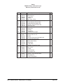
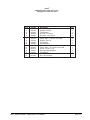
Clarke®
FOCUS S17/20, L17/20 and L17 Cyl.
Recovery Tank Parts List 1/05
Ref. #
1
2
3
4
5
6
6A
6B
6C
7
8
9
10
11
12
13
14
15
16
17
18
19
20
21
22
23
24
25
26
27
28
29
30
NI
Clarke® Operator's Manual
Part No.
80176A
30207A
30065A
692409
80196A
10660A
40002A
56459B
59877A
30218A
30227A
30226A
52560A
30225A
82100A
872102
962957
52206A
43402A
41809A
80193A
832002
35102A
61459A
980603
80110A
920296
752020
51060A
30482A
61451B
962666
53179A
77093A
Description
Screw, M5 x .8 x 12mm Pan Head
Recovery Lid
Lid Gasket
Chain
Nut, M5 x .8 Hex
Float Switch Kit (includes 6A, 6B, 6C)
Float Switch (included in #6)
Strain Relief (included in #6)
Washer, Seal (included in #6)
Recovery Tank
Drain Housing
Drain Plug
O-Ring
Drain Body
Locknut, 1/2" Conduit
Nylon Clip, 5/16 OD
Screw, #10-16 x 1/2
Chain
Housing, Connector (included in 6A)
Contact (included in 6A)
Screw, M5 x .8 x 10mm Pan Head
Drain Valve Clamp
Drain Hose
Latch Plate
Washer, LK #10 Ext Tooth
Hose Clamp
Nut, 10-24
Clamp
Vacuum Hose
Squeegee Hose
Vacuum Screen
Screw, 10-24 x 3/4 Pan Head
Red Cable Tie
Label, Falling Parts
-FOCUS S17/L17 and S20/L20
Qty
1
1
1
1
1
1
1
1
1
1
1
1
1
1
1
2
2
1
2
2
4
1
1
1
2
1
1
1
1
1
1
1
1
1
Page -35-
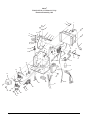
Clarke®
FOCUS S17/20, L17/20 and L17 Cyl.
Solution Tank & Front Cover Assembly 1/05
1
2
3
46
5
4
7
2
6
6
41
42
45
2
40
39
44
9
43
8
7
6
2
13
12
18
17
3
16
37
39
38
15
14
14
19
6
12
36
20
2
21
47
32
22
35
34
23
33
23
21
24
26
21
27
28
Page
-36-
Clarke® Operator's Manual -FOCUS S17/L17 and S20/L20
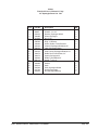
Clarke®
FOCUS S17/20, L17/20 and L17 Cyl.
Solution Tank & Front Cover Parts List 1/05
Ref. #
1
2
3
4
5
6
7
8
9
12
13
14
15
16
17
18
19
20
21
22
23
24
26
27
28
32
33
34
35
36
37
38
39
40
41
42
43
44
45
46
47
NI
Part No.
80199A
980614
87026A
40724A
61297B
80179A
80180A
61298B
52551A
52548A
30608A
80202A
87036A
80196A
80209A
61457A
61456A
30219A
50248A
53607A
30172A
51204A
820207
30453A
59614A
51518A
51526A
55189A
31242A
30239A
30222A
61280A
980603
52552A
41809A
43401A
80210A
80176A
61345A
40817A
53562A
70668A
Description
Nut, M6 x 1 Hex Nylock
Lock Washer, 1/4" Ext. Tooth
Flat Washer, 1/4"
Vacuum Motor
Front Motor Mount
Screw, M6 x 1 x 15mm, Pan Head
Screw, M6 x 1 x 30mm, Pan Head
Rear Motor Mount
Battery Strap
Screw Tab
Front Cover
Screw, M5 x .8 x 15mm, Pan Head
Flat Washer, #10
Nut, M5 x .8 Hex Nylock
Shoulder Bolt, M5 x 6 x 8mm
Left Front Cover Bracket
Right Front Cover Bracket
Solution Tank
Hose Clamp
Elbow, 1/4 NPT x 3/8
Hose
Valve, Solution
Adapter
Hose
Battery Drain Valve
Bushing
Hosebarb, 3.8 x 90°
Hosebarb, 1/2 x 90°
Bushing
Level, Drain Hose
Solution Lid
Drain Hose Hanger
Lock Washer, #10 Ext. Tooth
Battery Strap, w/Buckle
Contact, Connector
Housing, Connector
Screw, M6 x 1 x 10mm, Flat Head
Screw, M5 x .8 x 12mm, Pan Head
Hinge Bracket
Brush Mechanism
Filter Bowl
Label, FOCUS (Front Cover)
Qty
2
10
4
1
1
8
2
1
1
4
1
6
4
4
2
1
1
1
6
1
2
1
1
1
1
2
2
2
2
1
1
1
4
1
2
2
2
2
1
2
1
1
NI = Not Illustrated
Clarke® Operator's Manual
-FOCUS S17/L17 and S20/L20
Page -37-
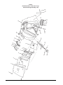
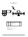
Clarke®
FOCUS S17/20, L17/20 and L17 Cyl.
Electrical Assembly 1/05
1
7
2
1
2
51
42 43
3
41
4
5
40
6
8
41
40
11
44
9
39
45
10
12
7
38
46
47
48
15
16
13
17
18
49
19
37
50
20
36
35
23
21
24
34
2
24
30
28
32
22
26
27
25
29
2
30
33
2
31
30
Page
-38-
Clarke® Operator's Manual -FOCUS S17/L17 and S20/L20
14
Clarke®
FOCUS S17/20, L17/20 and L17 Cyl.
Electrical Parts List 1/05
Ref. #
1
2
3
4
5
6
7
8
9
10
11
12
13
14
15
16
17
18
19
20
21
22
23
24
25
26
27
28
29
30
31
32
33
34
35
36
37
38
39
40
41
42
43
44
45
46
47
48
49
50
51
Clarke® Operator's Manual
Part No.
Description
80179A
980614
30097A
40635A
980607
962980
30287A
52548A
30175A
40614A
40615A
40611A
40609A
980692
438360
80178A
80202A
60975A
85389A
980666
60976A
52557A
40631A
80186A
40592A
80221A
40630A
40629A
193951
80205A
80204A
40169A
80208A
41811A
40612A
80222A
40633A
40634A
41810A
40613A
46106A
40626A
80206A
980603
80169A
80199A
60265A
60977A
61084A
61332A
52562A
80196A
912216
43006A
77094A
77092A
Screw, M6 x 1 x 15mm, Pan Head
Washer, Lock 1/4" Ext. Tooth
Insulator
Squeegee Switch
Washer, Lock #6 Ext. Tooth
Screw, 6-32 x 1, Pan Head
Strain Relief
Screw Tab
Squeegee Cam
Battery Charger, 115V, 50/60 Hz
Battery Charger, 230V, 50/60 Hz
Cord, Power Supply 115V
Cord, Power Supply 230V, European
Washer, Flat 5/16" SS
Squeegee Lift Spring
Shoulder Bolt, M6 x 8 x30mm
Screw, M5 x .8 x 15mm, Pan Head
Squeegee Cable
Screw, 3/8-16 x 5/8
Washer, 3/8" Ext. Tooth
Squeegee Lever
Squeegee Knob
Traverse Harness
Eyebolt, #10-24
Traverse Controller
Screw, M4 x .7 x 20mm, Pan Head
Main Harness, Traverse
Main Harness, Non-Traverse
Grommet, 8.5"
Screw, M5 x .8 x 20mm, Pan Head
Nut, M3 x .5, Nylock
Solenoid, Vacuum
Screw, M6 x 1 x 10mm, Pan Head
Contactor, Main
Red Battery Cable
Screw, M4 x .7 x 10mm, Pan Head
Relay, DPDT, 115V
Relay, DPDT, 230V
Contactor, Brush
Black Battery Cable
Rectifier
Terminal Block
Screw, M3 x .5 x 20mm, Pan Head
Washer, Lock #10 Ext. Tooth
Nut, M5 x .8 Hex
Nut, M6 x 1, Nylock
Nut Plate
Squeegee Lift Mount
Electrical Panel, Traverse
Electrical Panel, Non-Traverse
Strain Relief Bushing
Nut, M5 x .8 Nylock
Fuse, 15A
Fuse Holder
Label, Ground
Label, Gases & Chemicals
-FOCUS S17/L17 and S20/L20
Qty
Qty
S17/20 L17/20
6
12
1
1
2
2
1
2
1
1
1
1
1
2
1
1
1
1
1
1
1
1
1
3
1
1
1
2
1
6
1
1
2
1
1
1
1
1
1
2
2
2
1
1
1
1
1
1
1
1
1
1
6
12
1
1
2
2
1
2
1
1
1
1
1
2
1
1
1
1
1
1
1
1
1
1
1
3
1
1
1
2
1
6
1
1
2
1
1
1
1
1
1
2
2
2
1
1
1
1
1
1
1
1
1
1
Page -39-
20B
27
29
28
30
1
3
4
31
5
6
7
8
1
11
9
12 13
10
14
16
15
17
26
18
21
20
19
25 23
24 23
22
32 33
Clarke®
FOCUS S17/20, L17/20 and L17 Cyl.
Control Housing Assembly 1/05
Page
-40-
Clarke® Operator's Manual -FOCUS S17/L17 and S20/L20
Clarke®
FOCUS S17/20, L17/20 and L17 Cyl.
Control Housing Parts List 1/05
Ref. #
1
3
4
5
6
7
8
9
10
11
12
13
14
15
16
17
18
19
20
20B
21
22
23
24
25
26
27
28
29
30
31
32
33
Part No.
962957
70352A
60979A
52555A
60978A
87036A
80196A
40597A
962330
30214A
50961A
80192A
30213A
980608
40126A
80191A
52556A
30220A
30228A
47380A
55413A
80230A
87052A
41422A
41433A
41422A
41423A
80229A
40135A
980666
60259A
50962A
962262
70080A
83010A
Clarke® Operator's Manual
Description
Screw, 10-16 x 1/2"
Membrane Switch
Control Panel
Lever Gasket
Wear Plate
Washer, Flat #10
Nut, M5 x .8, Nylock
Panel Circuit Board
Screw, 6-32 x 3/8" Pan Head
Switch Lever
Spring, Switch
Screw, M5 x .8 x 16mm, Oval Head
Switch Housing
Washer, Flat #6
Switch Assembly
Screw, M3.5 x 6 x 10mm, Pan Head
Reverse Switch
Control Handle, Traverse
Control Handle, Non-Traverse
Key Switch
Key, Spare
Washer, Nylon
Washer, Key Switch
Circuit Breaker, 25A
Circuit Breaker, 40A
Circuit Breaker, 25A
Circuit Breaker, 5A
Arrow Clip, Nylon
Potentiometer Harness
Washer, Lock 3/8"
Potentiometer Retainer
Control Knob
Screw, Set 8-32 x 1/2" (included in #30)
Plate, Warning
Rivet, Pop
-FOCUS S17/L17 and S20/L20
Qty
Qty
Qty
S17/20 L17/20 L17 Cyl
6
6
6
1
1
1
1
1
1
1
1
1
1
1
1
3
3
3
3
3
3
1
1
1
4
4
4
2
2
2
4
4
4
4
4
4
2
2
2
4
4
4
2
2
2
4
4
4
1
1
1
1
1
1
1
1
1
1
1
1
1
2
3
1
1
1
2
2
2
1
1
1
1
1
1
1
1
1
1
1
1
1
1
1
2
2
2
Page -41-
Clarke®
FOCUS S17/20, L17/20 and L17 Cyl.
Squeegee Lift Assembly 1/05
1
2
3
4
7
5
8
16
6
11
17
7
9
8
10
11
12
15
14
5
13
Page
-42-
Clarke® Operator's Manual -FOCUS S17/L17 and S20/L20
Clarke®
FOCUS S17/20, L17/20 and L17 Cyl.
Squeegee Lift Parts List 1/05
Ref. #
1
2
3
4
5
6
7
8
9
10
11
12
13
14
15
16
17
Clarke® Operator's Manual
Part No.
80196A
87036A
61305A
80199A
80198A
980652
80195A
87026A
61292A
61296A
980651
80194A
80101A
61461A
60256A
80197A
81104A
Description
Nut, M5 x .8, Nylock
Washer, Flat #10
Tube Bracket
Nut, M6 x 1, Nylock
Nut, M8 x 1.25, Nylock
Washer, Lock 5/16"
Screw, M6 x 1 x 20mm, Hex Head
Washer, Flat 1/4"
Pin Bracket
Squeegee Arm
Washer, Flat 5/16"
Screw, M8 x 1.25 x 30mm, Hex Head
Screw, 1/4-20 x 3 1/4"
Squeegee Swivel Spacer
Pivot Bracket
Screw, M8 x 1.25 x 20mm, Hex Head
Nut, 1/4-20 Nylock
-FOCUS S17/L17 and S20/L20
Qty
1
1
1
2
2
1
4
2
1
1
2
1
1
1
1
1
1
Page -43-
Clarke®
FOCUS S17/20, L17/20 and L17 Cyl.
32" Squeegee Assembly 1/05
1
2
21
21
5
3
19
4
5
4
18
20
21
7
17
8
9
10
11
12
13
22
14
16
Page
-44-
15
Clarke® Operator's Manual -FOCUS S17/L17 and S20/L20
Clarke®
FOCUS S17/20, L17/20 and L17 Cyl.
32" Squeegee Parts List 1/05
Ref. #
1
2
3
4
5
6
7
8
9
10
11
12
13
14
15
16
17
18
19
20
21
22
Clarke® Operator's Manual
Part No.
80252A
980657
60243A
30049B
81104A
60254A
50958A
30048A
60234A
50835A
930086
60232A
30067A
30047A
30066A
80011A
81301A
34260B
25201A
60358A
61370A
80280A
Description
Screw, ¼-20 x 1 Hex SS
Washer, ¼ Lock
Bracket, Squeegee Wheel
Wheel, Squeegee
Nut, ¼-20
Bolt, Shoulder 5/16x 2¼
Ring, 3/8 ID Snap
Wheel, Guide, 4 Inch Diameter
Channel, Squeegee Weldment 32”
Latch, Squeegee Clamp
Rivet, 3/16 x .450 Aluminum
Strap, Clamp, Squeegee Retainer 32
Blade, Rear, Gum Rubber, 32”
Spacer, Squeegee 32
Blade, Front Ribbed 32”
Screw, 3/8-16 x 3
Nut, 3/8-16 Jam SS
Gasket
Knob
Shim, Squeegee Wheel
Weight, Squeegee
Nut, Squeegee Backup
-FOCUS S17/L17 and S20/L20
Qty
4
4
2
4
2
2
2
2
1
1
2
1
1
1
1
2
2
1
2
2
4
2
Page -45-
Clarke®
FOCUS S17/20, L17/20 and L17 Cyl.
Frame Assembly 1/05
4
7
37
35
8
1
36
1
5
24
9
2
3
12
16
1
1
34
2
31
11
2
12
12
32
10
33
11 10
17
14
15
18
12
24
12
31
12
12
19
20
31
13
1 2
21
12
15
22
23B
23A
12
29
2
30
12
27B
24
24
25
26
38 28
27A
Page
-46-
Clarke® Operator's Manual -FOCUS S17/L17 and S20/L20
Clarke®
FOCUS S17/20, L17/20 and L17 Cyl.
Frame Parts List 1/05
Ref. #
1
2
3
4
5
7
8
9
10
11
12
13
14
15
16
17
18
19
20
21
22
23A
23B
24
25
26
27A
27B
28
29
30
31
32
33
34
35
36
37
38
Part No.
80199A
87026A
80204A
80225A
54179A
80196A
61077A
80164A
61075A
80165A
980651
980692
61592A
80173A
80195A
980614
61302A
47422B
80203A
59610A
51526A
52635A
30311A
61455A
61076A
80197A
57423A
87616A
61436A
61437A
980205
60289A
81104A
80198A
61079A
61460A
61073A
80223A
980645
80226A
980652
Clarke® Operator's Manual
Description
Nut, M6 x 1, Nylock
Washer, Flat 1/4" SS
Nut, M3 x .5 Nylock
Spring, Front (1.25" long)
Spring, Front (2.25" long)
Nut, M5 x .8 Nylock
Rear Actuator Bracket
Shoulder Bolt, M5 x 6 x 20mm
Actuator
Shoulder Bolt, M6 x 8 x 12mm
Washer, Flat 5/16"
Washer, Flat 5/16" SS
Lift Bracket
Bolt, M6 x 1 x 65mm Hex Head
Screw, M6 x 1 x 20mm Hex Head
Washer, Lock 1/4" Ext Tooth
Static Strap
Switch, Wisker
Screw, M3- x 5 x 30mm Pan Head
Solution Valve
Hosebarb, 90°, 3/8 x 3/8
Hosebarb, 90°, 3/8 x 1/2
Hose
Axle, Non-Traverse
Transaxle
Screw, M8 x 1.25 x 20mm Hex Head
Snap Ring
Washer, Nylon
Wheel, Non-Traverse
Wheel, Traverse
Washer, 5/16" Fender
Transaxle Clamp
Nut, 1/4-20 ESNA SS
Nut, M8 x 1.25 Nylock
Head Bracket
Caster Assembly
Main Frame
Nut, M10 x 1.5 Nylock
Washer, Flat 3/8"
Spring, Rear (2" long)
Washer, Lock 5/16"
-FOCUS S17/L17 and S20/L20
Qty
S17
5
7
2
1
1
1
1
1
2
2
18
1
1
2
1
2
1
1
1
1
12
2
4
2
2
8
1
1
1
1
1
1
2
Qty
L17
6
17
2
1
1
1
1
1
2
2
18
1
1
3
2
1
1
2
1
1
1
1
10
2
2
8
8
1
1
1
1
1
1
-
Qty
L17 Cyl
6
17
2
1
1
1
1
1
2
2
18
1
1
3
2
1
1
2
1
1
1
10
2
2
8
8
1
1
1
1
1
1
-
Qty
S20
5
7
2
1
1
1
1
1
2
2
18
1
1
2
1
2
1
1
1
12
2
4
2
2
8
8
1
1
1
1
1
1
2
Qty
L20
6
17
2
1
1
1
1
1
2
2
18
1
1
3
2
1
1
2
1
1
1
10
2
2
8
8
1
1
1
1
1
1
-
Page -47-
Page
-48-
45
16
46
10
58
49
47
10
44
25
43
51
42
48
52
50
41
29
40
20
58
53 54
38
3
39
6
25
55
57
37
36
56
3
10
35
60
7 29 32
31
59
34
30
11
6
3
2
33
3
7
1
5
27
4
26
7 29
12 13
8
9
5
28
4
6
25
14
3
15
6
7
24
17
23
18
16
19
20
10
21
22
Clarke®
FOCUS L17 Cylindrical
Cylindrical Head Assembly 1/05
Clarke® Operator's Manual -FOCUS S17/L17 and S20/L20
Clarke®
FOCUS L17 Cylindrical
Cylindrical Head Parts List 1/05
Ref. #
1
2
3
4
5
6
7
8
9
10
11
12
13
14
15
16
17
18
19
20
21
22
23
24
25
26
27
28
29
30
31
32
33
34
35
36
37
38
39
40
41
42
43
44
45
46
47
48
49
50
51
52
53
54
55
56
57
58
59
60
Clarke® Operator's Manual
Part No.
80198A
980652
980692
80165A
980651
80199A
87026A
80196A
61306A
80176A
61080A
915082
50436A
30230A
61286A
ref.
61398A
61449A
52477A
80180A
30545A
30209A
30208A
30544A
53399A
80179A
61282A
80214A
980657
61396A
21058A
57994A
61397A
52818A
80178A
59932A
80187A
80177A
61448A
80208A
30049B
30235A
61287A
70465A
61285A
61283A
61450A
77091A
782002
50248A
10387A
61430A
41602A
41601A
930113
61288A
80158A
53182A
80249A
962262
Description
Qty
Nut, M8 x 1.25 Nylock
3
Washer, 5/16" Lock
3
Washer, 5/16" Flat SS
13
Shoulder Bolt, M6 x 8 x 12mm
2
Washer, 5/16" Flat
2
Nut, M6 x 1 Nylock
8
Washer, 1/4" Flat SS
8
Nut, M5 x .8 Nylock
2
Switch Bracket
1
Screw, M5 x . 8 x 12mm Pan Hd
17
Head Bracket
1
Key, 3/16" Sq. X 3/4"
2
Drive Pin
4
Debris Tray
1
Brush Shaft
2
See accessories page, cyl. brush 2
Brush Spacer
2
Door, L.H. Brush
1
Clamping Knob
2
Screw, M6 x 1 x 30mm Pan Hd
8
Skirt, Brush Door
2
Bumper, Brush Door
2
Bumper, Belt Cover
2
Skirt, Belt Cover
2
Flange Bearing
4
Screw, M6 x 1 x 15mm Pan Hd
4
Cover L.H. Belt
1
Screw, M6 x 1 x 12 Hex Head
2
Washer, 1/4" Lock
10
Motor Pulley
2
Brush Housing
1
Screw, M6 x 20mm, Hex Head
4
Brush Pulley
2
Drive Belt
2
Shoulder Bolt, M6 x 8 x 30mm
2
Front Wheel
2
Bolt, M8 x 1.25 x 30mm Hex Hd.
3
Shoulder Bolt, M6 x 8 x 60mm
2
Roller Bracket
2
Screw, M6 x 1 x 10mm Pan Hd
4
Wheel, 1 x 2 x 5/16
4
Bumper, Housing
1
Bumper Retainer
1
Label, 17
1
Motor Cover
1
Door, R.H. Brush
1
Cover, R.H. Belt
1
Label, Moving Parts
2
Clamp, Solution Tube
1
Clamp, 3/8 Hose
2
Solution Tube Assembly
1
Motor
2
Housing, Connector
4
Contact, Connector
4
Rivet, 1/8"
3
Tray Rail
1
Key, 1/8" Sq. x 1/2"
2
Cap, Tube
2
Screw, M5-.8 x 12 mm HH
2
Screw, Set 8-32 x 1/4
2
-FOCUS S17/L17 and S20/L20
Page -49-
20
18
15
14
6 5
21
8
9
23
24
25
26
27
28
22
9
31
34
1
30
2
29
7
32
33
17
11
19
16
11
9
4
3
13
10
35
12
5
6
8
7
Clarke®
FOCUS S17/20 & L17/20 Rotary
Rotary Disk Head Assembly 1/05
Page
-50-
Clarke® Operator's Manual -FOCUS S17/L17 and S20/L20
Clarke®
FOCUS S17/20 & L17/20 Rotary
Rotary Disk Head Parts List 1/05
Ref. #
Part No.
Description
1
2
3
4
5
6
7
8
9
10
11
12
13
41602A
41601A
40591A
20014A
87026A
80199A
80165A
980651
80196A
61306A
980692
80249A
61078A
61593A
98451A
80184A
20308A
980679
980210
980652
80197A
30216A
30607A
30217A
30599A
70667A
70897A
66550A
80224A
980643
920278
61289A
52515A
87036A
80227A
980645
80202A
80169A
77091A
Housing, Connector
Contact, Connector
Brush Motor
Motor Shim
Washer, Flat 1/4"
Nut, M6 x 1 Nylock
Shoulder Bolt, M6 x 8 x 12mm
Washer, Flat 5/16"
Nut, M5 x .8 Nylock
Switch Bracket
Washer, Flat 5/16"
Screw, M5 x .8 x 12mm Hex Head
Motor Mount Bracket
Motor Mount Bracket
Washer, Lock 7/16"
Bolt, M10 x 1.5 x 25mm Hex Head
Motor Adaptor
Washer, Flat 3/4"
Washer, Impeller
Washer, Lock 5/16"
Screw, M8 x 1.25 x 20mm Hex Head
Upper Brush Housing
Upper Brush Housing
Lower Brush Housing
Lower Brush Housing
Label, 17
Label, 20
Pin Assembly
Shoulder Bolt, M5 x 6 x 16mm
Washer, Flat
Nut, 1/2-20 SS Hex
Motor Cover Rod
Bearing Sleeve
Washer, Flat #10
Extension Spring
Washer, Flat 3/8"
Screw, M5 x .8 x 15mm, Pan Head
Nut, M5 x .8 Hex
Label, Moving Parts
14
15
16
17
18
19
20
21
22
23
24
25
26
27
28
29
30
31
32
33
34
35
Clarke® Operator's Manual
-FOCUS S17/L17 and S20/L20
Qty
S17
1
1
1
1
2
2
2
2
3
1
2
2
1
4
4
1
1
1
1
1
1
1
1
1
2
2
1
1
1
1
1
2
1
2
1
Qty
L17
1
1
1
1
2
2
2
2
3
1
2
2
1
4
4
1
1
1
1
1
1
1
1
1
2
2
1
1
1
1
1
1
2
1
Qty
S20
1
1
1
1
2
2
2
2
3
1
2
2
1
1
4
4
1
1
1
1
1
1
1
1
1
1
1
1
2
2
1
1
1
1
1
1
2
1
Qty
L20
1
1
1
1
2
2
2
2
3
1
2
2
1
1
4
4
1
1
1
1
1
1
1
1
1
1
1
1
2
2
1
1
1
1
1
1
2
1
Page -51-
Clarke®
FOCUS S17/20 & L17/20 Rotary
Gearbox Assembly and Parts List 1/05
8
7
4
5
3
2
1
Ref #
1
2
3
4
5
7
9
10
11
Page
-52-
Part No.
57846A
507641
52050A
56668A
51176A
902605
58144A
NI
52855A
Description
Ring, Snap
Seal, Oil, Small
Cap End
O-Ring
Bearing, Large
Bearing, Small
Seal, Oil Large
Darina EP2 Grease
Complete Gearbox Asm.
Qty
1
1
1
1
1
1
1
4 oz.
1
Clarke® Operator's Manual -FOCUS S17/L17 and S20/L20
Clarke®
FOCUS S17/20 & L17/20 Rotary
Brush Motor Assembly and Parts List 1/05
13
7
12
1
12
2
Seam Location
13
3
14
16
4
15
5
6
17
8
9
10
11
Item
1
2
3
4
*5
Part No.
56478A
50142A
902654
902550
6
7
8
9
10
11
12
13
* 14
15
16
17
50520A
56480A
962546
50517A
448396
40826A
55657A
55656A
50515A
80501A
54238A
Description
Qty
Stator Frame Assembly (w/Magnets & Clips)
1
Armature Assembly (w. B.E. & F.E. Bearings)
1
Bearings B.E.
1
Bearing F.E.
1
Commutator Bracket Assembly
1
(w/Brush BRD Assembly Leads)
Commutator Bracket
1
Strain Relief
2
Brush Board Screw
2
Brush Board Assembly (w/ Springs & Brushes)
1
Brush Spring
4
Brush Assembly
4
Lead Assembly
1
Lead Assembly
1
Helical Washer
1
Thru Bolt
2
Shaft Key
1
B.E. Bracket Assembly (Gear Box)
1
* NOTE: Parts not available at this time.
Clarke® Operator's Manual
-FOCUS S17/L17 and S20/L20
Page -53-
Clarke®
FOCUS L17/L20 & L17 Cylindrical
Transaxle Drawing 1/05
BLK
RED
4, 5
1
3
2
6
Item
1
2
Part No.
10135A
51056A
Description
Wheel Flange Kit
Transaxle Mounting Sleeve
Qty
2
2
3
4
40593A
40594A
Motor Brush
Motor Urethane Sleeve
2
1
5
6
40595A
40596A
Motor
Transaxle Only
1
1
Specifications:
- Motor: 24VDC, Permanent Magnet, Tenv
- Transaxle: 30:1 Ratio
- Gear Oil: Mobile SHC634 12 oz.
Page
-54-
Clarke® Operator's Manual -FOCUS S17/L17 and S20/L20
BLK
RED
RED
YEL
Clarke®
FOCUS S17/20
Connection Diagram 1/05
Clarke® Operator's Manual
-FOCUS S17/L17 and S20/L20
Page -55-
Clarke®
FOCUS S17/20
Electrical Schematic 1/05
Page
-56-
Clarke® Operator's Manual -FOCUS S17/L17 and S20/L20
BLK
RED
RED
YEL
Clarke®
FOCUS L17/20
Connection Diagram 1/05
Clarke® Operator's Manual
-FOCUS S17/L17 and S20/L20
Page -57-
Clarke®
FOCUS L17/20
Electrical Schematic 1/05
Page
-58-
Clarke® Operator's Manual -FOCUS S17/L17 and S20/L20
CLARKE PRODUCT SUPPORT BRANCHES
U. S. A. Locations
CORPO
PRODUCTION FACILITIES
Clarke® , Springdale, Arkansas
2100 Highway 265
Springdale, Arkansas 72764
(479) 750-1000
Customer Service - 1-800-253-0367
Technical Service - 1-800-356-7274
American Lincoln®, Bowling Green, Ohio 43402
1100 Haskins Road
European Locations
PRODUCTION FACILITIES
ALTO Danmark A/S, Aalborg
Blytaekkervej 2
DK-9000 Aalborg
+45 72 18 21 00
ALTO Danmark A/S, Hadsund
Industrikvarteret
DK-9560 Hadsund
+45 72 18 21 00
SALES SUBSIDIARIES
SERVICE FACILITIES
®
Clarke , Elk Grove, Illinois 60007
2280 Elmhurst Road
(847) 956-7900
®
Clarke , Denver, Colorado 80204
1955 West 13th Ave.
(303) 623-4367
Clarke® Canada Ltd., Rexdale Ontario
24 Constellation Ct.
(416) 675-5830
ALTO Overseas Inc., Sydney (Australia)
1B/8 Resolution Drive
Caringbah NSW 2229
+61 2 9524 6122
Clarke®, Houston, Texas 77040
7215 North Gessner Road
713-937-7717
ALTO Cleaning Systems Asia Pte Ltd., Singapore
No. 17 Link Road
Singapore 619034
+65 268 1006
SERVICE AND SALES FACILITY
ALTO Deutschland GmbH, Bellenberg (Germany)
Guido-Oberdorfer-Straße 2-8
89287 Bellenberg
+49 0180 5 37 37 37
American Lincoln® / Clarke, Madison Heights,
Michigan 48071-0158
29815 John R.
(810) 544-6300
American Lincoln® / Clarke, Marietta, Georgia 30066
1455 Canton Road
(770) 973-5225
SALES AND DISTRIBUTION CENTER
Clarke®, Secaucus, NJ 07094
74 Henry Street
(201) 864-5503
Clarke®
Clarke American Sanders
A.L. Cook
Customer Service Headquarters and Factory
2100 Highway 265
Springdale, Arkansas 72764
(479) 750-1000
Technical Service
1-800-356-7274
ALTO Cleaning Systems (UK) Ltd., Penrith
Gilwilly Industrial Estate
Penrith
Cumbria CA11 9BN
+44 1768 868 995
ALTO France S.A. Strasbourg
B.P. 44, 4 Place d’Ostwald
F-67036 Strasbourg
Cedex 2
+33 3 8828 8400
ALTO Nederland B.V.
Postbus 65
3370 AB Hardinxveld-Giessendam
The Netherlands
+31 184 677 200
ALTO Sverige AB, Molndal (Sweden)
Aminogatan 18
Box 4029
S-431 04 Molndal
+46 31 706 73 00
ALTO Norge A/S, Oslo (Norway)
Bjornerudveien 24
N-1266
+47 2275 1770
Clarke® LIMITED U.S. WARRANTY
This Clarke Industrial/Commercial Product is warranted to be free from defects in materials and workmanship under
normal use and service, when operated and maintained in accordance with Clarke's Maintenance and Operations instructions. The warranty period is subject to the conditions stated below.
3 YEARS FOR PARTS AND 1 YEAR FOR SERVICE LABOR (See exceptions below)
Motors must be inspected for carbon motor brush wear at six-month intervals by an authorized Clarke repair station.
Failure to comply with the six-month inspection requirement or failure to replace worn motor brushes identified during the
inspection will void the warranty on the motors. Cost of the six-month inspection and replacement of carbon motor brushes is
the responsibility of the purchaser. In the event of a warranty claim on the motors, proof of inspection and any required motor
brush replacement must be provided. This warranty is extended only to the original purchaser for use of the product. It does not
cover normal wear parts such as electrical cable, rubber parts, hoses and motor brushes.
BATTERY WARRANTY
In addition to the items above, any original equipment Clarke Battery which becomes unserviceable under normal use within
a period of ninety (90) days from date of sale to the original user will be repaired or replaced with one of equal specification
at our option, F.O.B. any authorized Clarke Sales or Service Branch, with no charge to the user, except transportation
costs. After expiration of the above ninety (90) day period, any battery which fails under normal use will be adjusted to the
original user with a new battery of equal specification on an eighteen (18) months pro rate basis from the date of purchase.
Adjustment will be determined using the then current list price, plus transportation costs.
Warranty is rendered null and void if battery is not kept filled to the proper level with DISTILLED WATER.
Clarke: POLYDUR® AUTOMATIC SCRUBBER SOLUTION AND RECOVERY TANK EIGHT-YEAR U.S. GUARANTEE
Your new Clarke FOCUS 17 has polydur Solution and Recovery Tanks. Polydur is a rotationally molded, low-density
linear polyethylene that won't crack or dent, and withstands most corrosives and temperature extremes. Clarke backs
up your Polydur tanks with an eight-year guarantee. If a tank breaks or leaks under normal use within eight years of
the date of purchase, it will be replaced free.
Clarke UNIBODY FRAME EIGHT-YEAR U.S. WARRANTY
Clarke warranties the frame of the FOCUS 17 for a period of eight years against defects in materials and workmanship
under normal use and service.
STATED WARRANTIES ARE IN LIEU OF ALL OTHER WARRANTIES, EXPRESSED OR IMPLIED
Clarke's liability under this warranty is limited to repair of the product and/or replacement of parts and is given to purchaser
in lieu of all other remedies, including INCIDENTAL AND CONSEQUENTIAL DAMAGES.
THERE ARE NO EXPRESS WARRANTIES OTHER THAN THOSE SPECIFIED HEREIN. THERE ARE NO WARRANTIES
WHICH EXTEND BEYOND THE DESCRIPTION OF THE FACE HEREOF. NO WARRANTIES, INCLUDING BUT NOT LIMITED
TO WARRANTY OF MERCHANTABILITY, SHALL BE IMPLIED. A warranty registration card is provided with your Clarke
product. Return the card to assist Clarke in providing the performance you expect from your new floor machine.
If a difficulty develops with the product, you should: a) Contact the nearest authorized Clarke repair location or contact the
Clarke Service Operations Department, 2100 Highway 265, Springdale, Arkansas 72764, for the nearest authorized Clarke
repair location. Only these locations are authorized to make repairs to the product under this warranty. (b) Return the
product to the nearest Clarke repair location. Transportation charges to and from the repair location must be prepaid by the
purchaser. Clarke will repair the product and/or replace any defective parts with out charge within a reasonable time after
receipt of the product.
Clarke, 2100 Highway 265, Springdale, Arkansas 72764.
Clarke reserves the right to make changes or improvements to its machine without notice.
Always use genuine Clarke Parts for repair.
2100 Highway 265
Springdale, Arkansas, 72764