1
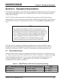
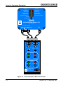
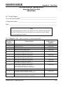
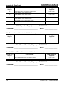
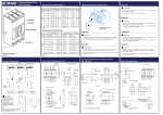
Union Switch & Signal Inc., an Ansaldo Signal company
SM 9020
1000 Technology Drive, Pittsburgh, PA 15219 ● 645 Russell Street, Batesburg, SC 29006
, Field
Test Unit
(N42252601)
for the
Electronic Circuit Controller
(ECC)
Operation
Copyright © 2002
Union Switch & Signal Inc.
SM 9020, Rev. 0, September 2002
Proprietary Notice
This document and its contents are the property of Union Switch & Signal Inc.
(hereinafter US&S). This document has been furnished to you on the following
conditions: no right or license under any patents or any other proprietary right in respect
to this document or its content is given or waived in supplying this document. This
document or its content are not to be used or treated in any manner inconsistent with the
rights of US&S, or to its detriment, and are not to be copied, reproduced, disclosed to
others, or disposed of except with the prior written consent of US&S.
Important Notice
US&S constantly strives to improve our products and keep our customers abreast of changes
in technology. Based on US&S’s experience, our customers will obtain the best possible
operational reliability by following the recommendations contained in the attached service
manual. The data contained herein purports solely to describe the product, and it is not a
warranty of performance or characteristics.
Within the scope of the attached manual, it is impossible to take into account every eventuality
that may arise with technical equipment in service. Please consult US&S local sales
representative in the event of any irregularities with our product.
We expressly decline liability for damages resulting from any improper handling or use of our
equipment, even if these instructions contain no specific indication in this respect. We stress
the fact that only genuine approved US&S spare parts should be used for replacements.
SM 9020, Rev. 0, September 2002
i
Revision History
Revision History
Original
ii
September 2002
SM 9020, Rev. 0, September 2002
Table of Contents
Table of Contents
Section 1 Introduction ......................................................................................................................................... 1-1
1.1
Application ................................................................................................................................... 1-1
1.2
Purpose of Manual ...................................................................................................................... 1-1
1.3
Conventions in Manual ................................................................................................................ 1-2
1.3.1
Abbreviations, Acronyms, and Definitions............................................................................ 1-2
1.4
Safety ......................................................................................................................................... 1-4
Section 2 Equipment Description...................................................................................................................... 2-1
2.1
Power Requirement..................................................................................................................... 2-1
Section 3 Functional Description ...................................................................................................................... 3-1
3.1
ECC DIAGNOSTIC INFORMATION ........................................................................................... 3-1
3.2
ECC Field Test Unit Controls ...................................................................................................... 3-2
Section 4 Installation ........................................................................................................................................... 4-1
Section 5 Operating Procedures........................................................................................................................ 5-1
5.1
ECC Diagnostic Testing .............................................................................................................. 5-1
5.2
ECC Vital/Non-Vital Sensor Testing............................................................................................ 5-5
5.2.1
Vital Sensor Test.................................................................................................................. 5-5
5.2.2
Non-Vital Sensor Test .......................................................................................................... 5-6
Section 6 Maintenance/Repair ........................................................................................................................... 6-1
Section 7 Technical Support .............................................................................................................................. 7-1
Appendix A
Data Sheet ...................................................................................................................................A-1
List of Figures
Figure 2-1 – Field Test Unit to ECC Connections...................................................................................... 2-2
List of Tables
Table 2-1 – WAGOâ Block to ECC Field Test Unit Power Wiring ............................................................. 2-1
Table 3-1– ECC Diagnostic LED Definitions ............................................................................................. 3-1
SM 9020, Rev. 0, September 2002
Page iii
Table of Contents
iv
!UNION SWITCH & SIGNAL!~
SM 9020, Rev. 0, September 2002
Section 1 – Introduction
Section 1. Introduction
This service manual describes the use and function of the Field Test Unit for the Electronic Circuit
Controller (ECC) for the M23E and M23 retrofitted style switch machines. For detailed information on
the installation, operation, maintenance, and adjustment of the ECC, please refer to Service Manual
6263A. For detailed information on the installation, operation, maintenance, and adjustment of the Mstyle machines, please refer to Service Manuals 6263 and 7100. The US&S Electronic Circuit
Controller (ECC) is used on US&S M-3 and M-23 (A or B) style switch machines. The (ECC) uses
four vital proximity sensors: two to detect the position of the switch points (normal or reverse) and two
to detect that the machine is fully locked (normal or reverse). The ECC is a microprocessor-based
controller that vitally monitors the state of the four vital proximity sensors and can identify each
possible sensor state (on, off, shorted, or open). In addition to the four vital proximity sensors, the ECC
can be equipped with an optional auxiliary point detection system. This system provides a normally
ON bipolar output to warn maintenance personnel of marginal switch machine operation. The sensing
threshold of each auxiliary sensor is offset from the vital point detector sensors by approximately 1/8”
to detect switch point displacement before the vital sensors indicate point detector bar movement. With
the auxiliary system, switch point displacement that is caused by debris build-up or expansion and
contraction of the rail can be detected before a switch failure occurs. The ECC provides advanced
diagnostics for identifying the current state of the machine and the indication state of an adjacent
(daisy-chained) machine. LEDs on the ECC indicate the delivery of indication power and auxiliary
indication power to the wayside, as well as provide information on motor power availability and the
state of the latch-out function.
1.1. Application
The ECC Field Test Unit is a diagnostic tool for testing an ECC while installed in a switch machine; it
can also test individual proximity sensors associated with a given switch machine.
WARNING
1. To avoid severe personal injury, open the gold nut test link in the
motor compartment prior to performing any internal machine
maintenance.
2. Always keep hands and feet clear of switch points and the internal
moving parts of the machine. Ensure that loose clothing is properly
secured prior to working on the switch machine.
The Field Test Unit attaches to the ECC and can test the ECC to ensure it is properly operating without
actually cycling the switch. While connected to the ECC, the Field Test Unit can also verify the proper
operation of the sensors on that switch machine.
1.2. Purpose of Manual
This service manual provides descriptive information on the use of the Field Test Unit for the US&S
Electronic Circuit Controller which is installed on the M23E, M-3, and M-23 Switch Machines. The
SM 9020, Rev. 0, September 2002
1-1
Section 1- Introduction
Field Test Unit itself is used in the maintenance of switch machines and is intended for use as a
diagnostic tool to provide feedback on the status of an ECC unit and all related proximity sensors.
1.3. Conventions in Manual
1.3.1.
Abbreviations, Acronyms, and Definitions
ac
alternating current
AAR
Association of American Railroads - Communication and Signal Section
(currently known as AREMA)
AREA
American Railway Engineering Association
AREMA
American Railway Engineering and Maintenance-of-Way Association (formerly
known as AAR)
AWG
American wire gauge
CAUTION
Caution statements indicate conditions that could cause damage to equipment
dc
direct current
ECC
Electronic Circuit Controller
Front of Machine
The physical area of the switch machine furthest from the motor
FRA
Federal Railroad Administration
Latch-Out
A device that does not allow switch point indication to restore if the switch point
moves away from the stock rail (point detection is momentarily lost). This
function will be activated if the point sensors are actuated before their
corresponding locking sensors are actuated.
Latch-Out
Restoration
The term latch-out restoration refers to resetting the machine to an operable switch
machine indication state from a latched-out condition.
LED
Light-emitting diode
Left Hand Switch
The position of a switch machine designated when the machine is located on the
left-hand side of the track, looking into the switch points in the direction of the
arrow as shown in Figure 1-1.
LHPC
“Left-hand point closed,” which refers to the switch point position when the point
is normally closed to the left-hand side, looking into the switch points in the
direction of the arrow as shown in Figure 1-1.
Point Detection
The positive indication achieved when the switch points are closed adequately
against the stock rail.
Locking
Locking is achieved when the lock box, connected to the slide bar, enters the
narrow locking notch of the lock rods and extends a minimum of 1/2” into the
locking rod
MCU
Motor control unit - a high-current, solid-state device used to control motor power
MOV
Metal oxide varistor (protection device for electronic components)
1-2
SM 9020, Rev. 0, September 2002
Section 1 – Introduction
LEFT- HAND
RIGHT- HAND
Figure 1-1- Left-Hand and Right-Hand Switch Machines
Non-Vital
Any circuit with a function that does not affect the safety of train operation
PCB
Printed circuit board
Rear of Machine
The physical area of the switch machine closest to the motor
Reference
Designator
An abbreviation assigned to designate an electrical component. It generally
consists of a capital letter and a number. Each letter designates a particular type of
component. For example, “L” identifies an inductor and “R” identifies a resistor.
Right Hand
Designator
The position of a switch machine designated when the machine is located on the
right-hand side of the track, looking into the switch points in the direction of the
arrow shown in Figure 1-1.
RHPC
“Right-hand point closed,” which refers to the switch point position when the
point is normally closed to the right-hand side of the track, looking into the switch
points in the direction of the arrow shown in Figure 1-1.
RMS
root-mean-square (method for expressing ac voltage rating
Switch Machine
Indication
A vital determination of a safe switch configuration, due to positive indication that
the switch machine has properly thrown, locked and detected switch point closure
Switch and Lock
Movement and/or
Switch Machine
A device which performs the three operations of unlocking, operating, and locking
a switch, movable point frog, or derail
US&S
Union Switch & Signal
Vital Circuit
Any circuit with a function that affects the safety of train operation
WAGO®
Registered trademark for WAGO Corporation
WARNING
Warning statements indicate conditions that could cause physical harm, serious
injury, or loss of life
SM 9020, Rev. 0, September 2002
1-3
Section 1- Introduction
1.4. Safety
Read and thoroughly understand this manual before attempting any of the procedures listed. Pay
particular attention to the WARNING and CAUTION statements that appear throughout this manual.
Always exercise care and observe standard precautions familiar to properly trained personnel. Always
adhere to all safety regulations stipulated by the railroad.
1-4
SM 9020, Rev. 0, September 2002
Section 2 – Equipment Description
Section 2. Equipment Description
For information regarding the system functions and components related to the electronic control system
inside of the switch machine refer to service manuals SM-6263A for M23 retrofit machines and SM7100 for M23E machines.
The ECC Field Test Unit connects directly to the three front connectors of the ECC and does not
require that the ECC be removed from a switch machine. When looking at the Field Test Unit from the
top side, the three cables are connected directly to the ECC for testing without crossing them (Figure
2-1).
NOTE
The cables for TB1 and JB1 are keyed in the same manner. Cable
lengths and cable ties should prevent cross connections; however, in
the event they are incorrectly re-connected and power is applied, the
ECC will appear as if no power has been applied. Because there is no
power, if cross connections are made, no damage to the unit will
occur. Swapping the connectors should return the ECC to normal
operation if no problems were found during diagnostic testing.
Connector keying will prevent any other incorrect connections.
The Field Test Unit is designed to simulate the equipment that is connected to the ECC and to
manipulate the states of that equipment to determine how the ECC responds. This provides fast
indication as to the status of the ECC and assists in the diagnosis of any problem that may arise.
2.1. Power Requirement
When connected to an ECC and power is applied to the Field Test Unit, the ECC will also be powered
on. The power required for the ECC Field Test Unit is 9.8Vdc to 16.2Vdc @ 1.5A and may be brought
from an independent external source or power may be fed from the WAGOâ terminal block and
connected as detailed in Table 2-1. (Approximately 8 feet of 20AWG wire (minimum) is
recommended for each of these connections.)
Table 2-1 – WAGOâ Block to ECC Field Test Unit Power Wiring
WAGOâ Terminal Block Connection
ECC Field Test Unit Connection
Signal
Block Number 20
Red Power Terminal
B12 – Battery +
Block Number 16
Black Power Terminal
N12 – Battery -
SM 9020, Rev. 0, September 2002
2-1
Section 2- Equipment Description
NORMAL
REVERSE
Point Detected
Point Detected
Point Locked
Point Locked
Indication Input
Indication Input
Indication Output
Indication Output
Auxiliary Point Detected
Auxiliary Point Detected
Latch Out
Motor Disabled
LED Diagnostics
UNION SWITCH & SIGNAL ECC
N47303401
Latch Out Restoration
(Press for 1 Second and Release)
TB1
JB1
TB2
BROWN
BLUE
BROWN
BLUE
VITAL SENSOR TEST NON-VITAL SENSOR TEST
NONE
LHPC
RHPC
DIRECTION
DISABLE
NONE
MANUAL
AUTO
LATCHOUT
Vital Sensors
ON
OFF
POINT SENSE 1
POINT SENSE 2
LOCK SENSE 1
LOCK SENSE 2
Non-Vital
Sensors
ON
OFF
AUXILIARY SENSE 1 AUXILIARY SENSE 2
HAND THROW
HAND CRANK
ECC FIELD TEST UNIT
UNION SWITCH & SIGNAL
645 Russell St.
Batesburg, SC 29006
POWER 9.8-16.2VDC
Figure 2-1 – Field Test Unit to ECC Connections
2-2
SM 9020, Rev. 0, September 2002
Section 3 – Functional Description
Section 3. Functional Description
3.1. ECC DIAGNOSTIC INFORMATION
The ECC is equipped with a series of LEDs to indicate the current state of the switch machine. Dualcolored LEDs are provided to indicate the state of each vital point and lock sensor. Green LEDs are
provided for indication input, indication output, and auxiliary sensor state definition. Red LEDs are
provided to determine when the motor is disabled and when the ECC is in a latched-out state. Table
3-1describes what the ECC diagnostics represent.
Table 3-1– ECC Diagnostic LED Definitions
LED Name
(NORMAL or
REVERSE)
Point Detected
State 1 / /Meaning
State 2 / Meaning
State 3 / Meaning
GREEN
Normal Point Sensor
Detected
RED
Point Sensor Not Detected
DARK
ECC Malfunctioning
Point Locked
GREEN
Normal Point Lock Sensor
Detected
RED
Point Lock Sensor Not
Detected
DARK
ECC Malfunctioning
Indication
Input
GREEN
Power is present to
generate an Indication
Output
GREEN
All ECC internal
diagnostics complete
correctly, machine state
dictates that all vital
sensors are in legal states,
configuration jumpers are
installed in legal positions,
and power is present to
generate the Indication
Output
GREEN
Auxiliary Point Sensor
Detected
RED
Machine is latched out
DARK
Power is not present to
generate Indication Output
RED
Motor power is disabled
DARK
Motor power is enabled
Indication
Output
Auxiliary Point
Detected
Latch Out
Motor Disabled
WARNING
The GOLD Nut must be
removed when
performing machine
maintenance
SM 9020, Rev. 0, September 2002
Flashing/Meaning
FLASHING RED
Point Sensor in
Indeterminate State, or
LHPC/RHPC not
selected
FLASHING RED
Point Lock Sensor in
Indeterminate State, or
LHPC/RHPC not
selected
FLASHING GREEN
ECC Malfunctioning
DARK
Power is not present to
generate Indication Output
even if the machine state
dictates, configuration
jumpers not installed or
multiple jumpers installed,
ECC internal diagnostics
failure
FLASHING GREEN
ECC Malfunctioning
DARK
Auxiliary Point Sensor Not
Detected
DARK
Machine is not latched out
FLASHING GREEN
ECC Malfunctioning
FLASHING RED
No latchout mode
selected, or multiple
latchout modes selected
FLASHING RED
ECC internal diagnostics
fail (Both Indication
Input LEDs will be
GREEN when using the
Field Test Unit)
NOTE: When using the
Field Test Unit, if this
state exists the ECC box
has failed and needs to
be replaced
3-1
Section 3- Functional Description
3.2. ECC Field Test Unit Controls
The controls on the ECC Field Test Unit are comprised of eight push button switches that are
illuminated GREEN when pushed in (ON state) and are illuminated RED when released (OFF state).
These buttons represent the eight possible sensors that can be installed in an M23E or M23 retrofit
switch machine and simulate the LEDs on the ECC. Some configurations of switch machines do not
include all of the non-vital sensors, but the ECC does not distinguish this fact. It does not illuminate
the auxiliary sensor LEDs if they are not installed. The hand crank and hand throw sensors are
simulated on the WAGOâ terminal block by a resistor such that the ECC still reads a return current as
if they were installed. So regardless of the machine’s configuration, the ECC can still be tested using
the Field Test Unit as described below.
Two rotary switches simulate the jumper configurations that are contained in the junction box. The
DIRECTION rotary switch tells the ECC if the switch is configured as Left Hand Points Closed
(LHPC) or Right Hand Points Closed (RHPC). The LATCHOUT rotary switch tells the ECC how to
respond to a latchout situation that can be simulated by the Field Test Unit. Both of these rotary
switches provide a NONE position to simulate no jumper being installed in the junction box for that
function. The ECC should respond correctly to that condition as well.
The two momentary push buttons at the top of the Field Test Unit are used to switch a vital or non-vital
sensor into the circuit for testing.
3-2
SM 9020, Rev. 0, September 2002
Section 4 – Installation
Section 4. Installation
Installation of the Field Test Unit is accomplished by removing the three cables connected to the ECC
and connecting the corresponding cables from the Test Unit to the ECC. Power is applied as described
in Section 2.1. No other connections are required. The ECC under test does not need to be removed
from the machine.
WARNING
1. To avoid severe personal injury, open the gold nut test link in the
motor compartment prior to performing any internal machine
maintenance.
2. Always keep hands and feet clear of switch points and the internal
moving parts of the machine. Ensure that loose clothing is properly
secured prior to working on the switch machine.
CAUTION
When reconnecting the machine cables, ensure the collars are turned
until they lock. Additionally, if power is fed from the WAGOâ
terminal block, carefully remove the wires without disturbing other
connections. If other connections are disturbed, removed, cut, or
otherwise disconnected, then breakdown or other types of testing may
be required to be performed again.
NOTE
The cables for TB1 and JB1 are keyed in the same manner. Cable
lengths and cable ties should prevent cross connections; however, in
the event they are incorrectly re-connected and power is applied, the
ECC will appear as if no power has been applied. If cross
connections are made, no damage to the unit will occur. Swapping
the connectors should return the ECC to normal operation if no
problems were found during diagnostic testing. Connector keying
will prevent any other incorrect connections.
SM 9020, Rev. 0, September 2002
4-1
Section 4- Installation
4-2
!UNION SWITCH & SIGNAL!~
SM 9020, Rev. 0, September 2002
Section 5 – Operating Procedures
Section 5. Operating Procedures
The ECC Field Test Unit may be used to fully gauge the performance of an ECC unit by connecting it
to the ECC as shown in Figure 2-1. It may also test individual vital and non-vital sensors used in a
switch machine.
NOTE
The sensors used for both Auxiliary Point Detection sensors and for both the
Hand Crank and Hand Throw functions are all electrically identical and are all
considered “non-vital” types. They may vary in barrel length.
The following procedure verifies the correct performance of an ECC and/or any of the proximity
sensors. Record the results of the procedure on the Data Sheet supplied in Appendix A.
5.1. ECC Diagnostic Testing
1. After power up, set switches on the Field Test Unit as follows:
DIRECTION = LHPC
LATCHOUT = DISABLE
POINT SENSE 1 = ON (GREEN)
POINT SENSE 2 = OFF (RED)
LOCK SENSE 1= ON (GREEN)
LOCK SENSE 2 = OFF (RED)
AUXILIARY SENSE 1 = ON (GREEN)
AUXILIARY SENSE 2 = OFF (RED)
HAND THROW = ON (GREEN)
HAND CRANK = ON (GREEN)
2. Verify that the LEDs on the ECC controller appear as follows:
NORMAL
REVERSE
POINT DETECTED = GREEN
POINT DETECTED = RED
LOCK DETECTED = GREEN
LOCK DETECTED = RED
INDICATION INPUT = GREEN
INDICATION INPUT = GREEN
INDICATION OUTPUT = GREEN
INDICATION OUTPUT = DARK
AUXILIARY POINT DETECTED = GREEN
AUXILIARY POINT DETECTED = DARK
LATCHOUT = DARK
MOTOR DISABLED = DARK
3. Move the DIRECTION switch on the Field Test Unit to the RHPC position. Verify that the LEDs
on the ECC controller appear as follows:
SM 9020, Rev. 0, September 2002
5-1
Section 5 – Operating Procedures
NORMAL
REVERSE
POINT DETECTED = RED
POINT DETECTED = GREEN
LOCK DETECTED = RED
LOCK DETECTED = GREEN
INDICATION INPUT = GREEN
INDICATION INPUT = GREEN
INDICATION OUTPUT = DARK
INDICATION OUTPUT = GREEN
AUXILIARY POINT DETECTED = DARK
AUXILIARY POINT DETECTED = GREEN
LATCHOUT = DARK
MOTOR DISABLED = DARK
4. Move the DIRECTION switch on the Field Test Unit to the NONE position. Verify that the LEDs
on the ECC controller appear as follows:
NORMAL
REVERSE
POINT DETECTED = BLINK RED
POINT DETECTED = BLINK RED
LOCK DETECTED = BLINK RED
LOCK DETECTED = BLINK RED
INDICATION INPUT = GREEN
INDICATION INPUT = GREEN
INDICATION OUTPUT = DARK
INDICATION OUTPUT = DARK
AUXILIARY POINT DETECTED = DARK
AUXILIARY POINT DETECTED = DARK
LATCHOUT = DARK
MOTOR DISABLED = RED
5. Move the DIRECTION switch on the Field Test Unit to the LHPC position. Set the POINT
SENSE 1 push button switch on the Field Test Unit to OFF or RED. Verify that the LEDs on the
ECC controller appear as follows:
NORMAL
REVERSE
POINT DETECTED = RED
POINT DETECTED = RED
LOCK DETECTED = GREEN
LOCK DETECTED = RED
INDICATION INPUT = GREEN
INDICATION INPUT = GREEN
INDICATION OUTPUT = DARK
INDICATION OUTPUT = DARK
AUXILIARY POINT DETECTED = GREEN
AUXILIARY POINT DETECTED = DARK
LATCHOUT = RED
MOTOR DISABLED = DARK
6. Set the POINT SENSE 1 push button switch on the Field Test Unit to ON or GREEN and verify
the LEDs on the ECC controller return to the configuration of Step 2.
7. Move the LATCHOUT switch on the Field Test Unit to the MANUAL position. Set the POINT
SENSE 1 push button switch on the Field Test Unit to OFF or RED. Verify that the LEDs on the
ECC controller appear as follows:
5-2
SM 9020, Rev. 0, September 2002
Section 5 – Operating Procedures
NORMAL
REVERSE
POINT DETECTED = RED
POINT DETECTED = RED
LOCK DETECTED = GREEN
LOCK DETECTED = RED
INDICATION INPUT = GREEN
INDICATION INPUT = GREEN
INDICATION OUTPUT = DARK
INDICATION OUTPUT = DARK
AUXILIARY POINT DETECTED = GREEN
AUXILIARY POINT DETECTED = DARK
LATCHOUT = RED
MOTOR DISABLED = DARK
8. Set the POINT SENSE 1 push button switch on the Field Test Unit to ON or GREEN, push the
Latchout Restore button on the ECC Controller for a minimum of 1 second and verify the LEDs on
the ECC controller return to the configuration of Step 2.
9. Move the LATCHOUT push button switch to the AUTO position. Set the POINT SENSE 1 push
button switch to OFF or RED. Verify that the LEDs on the ECC controller appear as follows:
NORMAL
REVERSE
POINT DETECTED = RED
POINT DETECTED = RED
LOCK DETECTED = GREEN
LOCK DETECTED = RED
INDICATION INPUT = GREEN
INDICATION INPUT = GREEN
INDICATION OUTPUT = DARK
INDICATION OUTPUT = DARK
AUXILIARY POINT DETECTED = GREEN
AUXILIARY POINT DETECTEDE= DARK
LATCHOUT = RED
MOTOR DISABLED = DARK
10. Set the LOCK SENSE 1 push button switch to OFF or RED, then set the POINT SENSE 1 push
button switch back to ON or GREEN, and then set the LOCK SENSE 1 push button switch back to
ON or GREEN. Verify the LEDs on the ECC controller return to the configuration of Step 2
above.
11. Move the LATCHOUT switch to the NONE position. Verify that the LEDs on the ECC controller
appear as follows:
NORMAL
REVERSE
POINT DETECTED = GREEN
POINT DETECTED = RED
LOCK DETECTED = GREEN
LOCK DETECTED = RED
INDICATION INPUT = GREEN
INDICATION INPUT = GREEN
INDICATION OUTPUT = DARK
INDICATION OUTPUT = DARK
AUXILIARY POINT DETECTED = GREEN
AUXILIARY POINT DETECTED = DARK
LATCHOUT = BLINK RED
MOTOR DISABLED = RED
SM 9020, Rev. 0, September 2002
5-3
Section 5 – Operating Procedures
12. Move the LATCHOUT switch to the MANUAL position. Set the AUXILIARY SENSE 1 push
button switch to OFF. Verify that the LEDs on the ECC controller appear as follows:
NORMAL
REVERSE
POINT DETECTED = GREEN
POINT DETECTED = RED
LOCK DETECTED = GREEN
LOCK DETECTED = RED
INDICATION INPUT = GREEN
INDICATION INPUT = GREEN
INDICATION OUTPUT = GREEN
INDICATION OUTPUT = DARK
AUXILIARY POINT DETECTED = DARK
AUXILIARY POINT DETECTED = DARK
LATCHOUT = DARK
MOTOR DISABLED = DARK
13. Reset the AUXILIARY SENSE 1 push button switch to ON. Set the AUXILIARY SENSE 2 push
button switch to ON. Verify that the LEDs on the ECC controller appear as follows:
NORMAL
REVERSE
POINT DETECTED = GREEN
POINT DETECTED = RED
LOCK DETECTED = GREEN
LOCK DETECTED = RED
INDICATION INPUT = GREEN
INDICATION INPUT = GREEN
INDICATION OUTPUT = GREEN
INDICATION OUTPUT = DARK
AUXILIARY POINT DETECTED = GREEN
AUXILIARY POINT DETECTED = GREEN
LATCHOUT = DARK
MOTOR DISABLED = DARK
14. Reset the AUXILIARY SENSE 2 push button switch to OFF. Set the HAND THROW push button
switch to OFF. Verify that the LEDs on the ECC controller appear as follows:
NORMAL
REVERSE
POINT DETECTED = GREEN
POINT DETECTED = RED
LOCK DETECTED = GREEN
LOCK DETECTED = RED
INDICATION INPUT = GREEN
INDICATION INPUT = GREEN
INDICATION OUTPUT = DARK
INDICATION OUTPUT = DARK
AUXILIARY POINT DETECTED = GREEN
AUXILIARY POINT DETECTED = DARK
LATCHOUT = DARK
MOTOR DISABLED = RED
15. Set the HAND THROW push button switch to ON. Set the HAND CRANK push button switch to
OFF. Verify that the LEDs on the ECC controller appear as follows:
5-4
SM 9020, Rev. 0, September 2002
Section 5 – Operating Procedures
NORMAL
REVERSE
POINT DETECTED = GREEN
POINT DETECTED = RED
LOCK DETECTED = GREEN
LOCK DETECTED = RED
INDICATION INPUT = GREEN
INDICATION INPUT = GREEN
INDICATION OUTPUT = DARK
INDICATION OUTPUT = DARK
AUXILIARY POINT DETECTED = GREEN
AUXILIARY POINT DETECTED = DARK
LATCHOUT = DARK
MOTOR DISABLED = RED
16. Set the HAND CRANK push button switch to ON. Set the HAND CRANK and HAND THROW
push button switches to OFF. Verify that the LEDs on the ECC controller appear as follows:
NORMAL
REVERSE
POINT DETECTED = GREEN
POINT DETECTED = RED
LOCK DETECTED = GREEN
LOCK DETECTED = RED
INDICATION INPUT = GREEN
INDICATION INPUT = GREEN
INDICATION OUTPUT = DARK
INDICATION OUTPUT = DARK
AUXILIARY POINT DETECTED = GREEN
AUXILIARY POINT DETECTED = DARK
LATCHOUT = DARK
MOTOR DISABLED = RED
17. Set the HAND CRANK and HAND THROW push button switches to ON. Verify the LEDs on the
ECC appear as in Step 2.
If the ECC responded correctly, the ECC is operating properly and should not be causing any problems.
In this case, any operating problem is due to the switch machine itself. Refer to the switch machine
manual for troubleshooting procedures.
If the ECC did not respond as it should have during the test, there is a problem with the ECC. Because
there are no field or shop maintenance procedures for the ECC, US&S recommends that the ECC be
replaced and the unit be returned to the US&S Batesburg location for repair.
5.2. ECC Vital/Non-Vital Sensor Testing
To test a vital or non-vital sensor, connect the Field Test Unit to an ECC per Section 4. Press down on
the black quick-connect terminals at the top of the unit for the type of sensor to be tested (VITAL
SENSOR TEST or NON-VITAL SENSOR TEST). Insert the two sensor wires per the color indicated
on the Field Test Unit label. See Figure 2-1.
5.2.1.
Vital Sensor Test
Initially when the sensor is connected it is not “in-circuit” for the ECC to be able to test. Press and
hold the momentary push button below the terminals labeled VITAL SENSOR TEST while
implementing all test steps.
SM 9020, Rev. 0, September 2002
5-5
Section 5 – Operating Procedures
Step 1:
If the sensor is not near a metallic or conductive surface (more than 1.2mm), the LED
that corresponds to Point Detected on the NORMAL side of the ECC will be steady RED indicating the
sensor is OFF or is not sensing a target.
Step 2:
Move the sensor near a metallic or conductive surface (less than 1.2mm). The LED that
corresponds to Point Detected on the NORMAL side of the ECC will be steady GREEN indicating the
sensor is in ON or is sensing a target.
Step 3: (Optional) Under normal circumstances the sensor is either ON or OFF. However, careful
placement of the sensor near a metallic or conductive surface (more than 1.2mm but less than 4mm)
may result in the Point Detected LED flashing RED indicating the sensor is in the indeterminate state
between ON and OFF. This may be difficult to achieve.
If the NORMAL side Point Detected LED is flashing RED, steady RED, or steady GREEN regardless
of sensor position, the sensor is not functioning properly. Additionally, if the NORMAL side Point
Detected LED does not function, as indicated in Steps 1 and 2, the sensor is not functioning properly.
5.2.2.
Non-Vital Sensor Test
Initially when the sensor is connected, it is not “in-circuit” for the ECC to be able to test. Press and
hold the momentary push button below the terminals labeled “NON-VITAL SENSOR TEST” while
implementing the test.
Step 1:
If the sensor is not near a metallic or conductive surface (more than 1mm), the LED that
corresponds to Auxiliary Point Detected on the NORMAL side of the ECC will be DARK indicating
the sensor is OFF or is not sensing a target.
Step 2:
Move the sensor near a metallic or conductive surface (less than 1mm). The LED that
corresponds to Auxiliary Point Detected on the NORMAL side of the ECC will be steady GREEN
indicating the sensor is ON or is sensing a target.
If the NORMAL side Auxiliary Point Detected LED is flashing GREEN, the ECC is not functioning
properly.
If the NORMAL side Auxiliary Point Detected LED is steady GREEN or DARK regardless of sensor
position, the sensor is not functioning properly. Additionally, if the NORMAL side Auxiliary Point
Detected LED does not function, as indicated in Steps 1 and 2, the sensor is not functioning properly.
If the sensor is not functioning properly, change the sensor. Repeat the test to verify proper operation of
the sensor before replacing it in the switch machine.
5-6
SM 9020, Rev. 0, September 2002
Section 6 – Maintenance / Repair
Section 6. Maintenance/Repair
There are no maintenance or repair procedures that field or shop personnel can perform on the Field
Test Unit. If there are any problems with the Field Test Unit, US&S recommends that the Unit be
returned to the US&S Batesburg location for repair.
Proper operation of the Field Test Unit may be verified by performing the tests in Section 5 using an
ECC and vital/non-vital sensors that are known to be properly functioning.
SM 9020, Rev. 0, September 2002
6-1
Section 6 – Maintenance / Repair
6-2
!UNION SWITCH & SIGNAL!~
SM 9020, Rev. 0, September 2002
Appendix 7 – Technical Support
Section 7. Technical Support
The Rapid Action Information Link Team (RAIL Team) is a group of experienced product and
application engineers ready to assist you to resolve any technical issues concerning this product.
Contact the RAIL Team at 1-800-652-7276 or by e-mail at [email protected].
SM 9020, Rev. 0, September 2002
7-1
Appendix A – Data Sheet
7-2
!UNION SWITCH & SIGNAL!~
SM 9020, Rev. 0, September 2002
Appendix A – Data Sheet
Appendix A
Data Sheet
SM 9020, Rev. 0, September 2002
A-1
Appendix A – Data Sheet
A-2
!UNION SWITCH & SIGNAL!~
SM 9020, Rev. 0, September 2002
Appendix A – Data Sheet
Test Data Sheet for Testing the ECC
Using the Field Test Unit
(N42252601)
ECC Serial Number: _____________________________________________________
Test Unit Serial Number: _________________________________________________
Technician’s Name: _____________________________________________________
Date: _________________________________________________________________
Note
In completing this form, please circle PASS or FAIL to indicate if the step has
Passed or Failed. Do not use check marks or try to mark out a result. Merely
circle the appropriate response.
ECC Diagnostic Test – (Refer to Section 5.1 for the test procedure.)
Section 5.1
Step No.
Switch /Position
LEDs Appear as
Required
1
Initial Switch Set UP
As stated in Step 1
2
Initial Switch Set Up
PASS / FAIL
3
DIRECTION switch in RHPC position
PASS / FAIL
4
DIRCTION switch in NONE position
PASS / FAIL
5
DIRECTION switch in LHPC position
POINT SENSE 1 pushbutton in OFF position
PASS / FAIL
6
POINT SENSE 1 pushbutton in ON position
PASS / FAIL
7
LATCHOUT switch in MANUAL position
POINT SENSE 1 pushbutton in OFF position
PASS / FAIL
8
POINT SENSE 1 pushbutton in ON position
PASS / FAIL
9
LATCHOUT switch in AUTO position
POINT SENSE 1 pushbutton in OFF position
PASS / FAIL
10
LOCK SENSE 1 pushbutton in OFF position
POINT SENSE 1 pushbutton in ON position
Then LOCK SENSE 1 pushbutton in ON position
PASS / FAIL
11
LATCHOUT switch in NONE position
PASS / FAIL
12
LATCHOUT switch in MANUAL position
AUXILIARY SENSE 1 pushbutton in OFF position
PASS / FAIL
13
AUXILIARY SENSE 1 pushbutton in ON position
AUXILIARY SENSE 2 pushbutton in ON position
PASS / FAIL
SM 9020, Rev. 0, September 2002
A-3
Appendix A – Data Sheet
Section 5.1
Step No.
Switch /Position
LEDs Appear as
Required
14
AUXILIARY SENSE 2 pushbutton in OFF position
HAND THROW switch in OFF position
PASS / FAIL
15
HAND THROW switch in ON position
HAND CRANK switch in OFF position
PASS / FAIL
16
HAND CRANK switch in ON position
HAND THROW switch in OFF position
Then HAND CRANK switch in OFF position
PASS / FAIL
17
HAND CRANK switch in ON position
HAND THROW switch in ON position
PASS / FAIL
ECC Operating Properly
PASS / FAIL
Technician: _________________________________ DATE: _________________
Vital Sensor Test – (Refer to Section 5.2.1 for the test procedure.)
Section 5.2.1
Step No.
Sensor Position
LEDs Appear as
Required
1
Sensor NOT NEAR metallic or conductive surface
PASS / FAIL
2
Sensor NEAR metallic or conductive surface
PASS / FAIL
Sensor > 1.2 mm but <4mm from metallic or conductive surface
PASS / FAIL
3 (Optional)
Vital Sensor Operating Properly
PASS / FAIL
Technician: _________________________________ DATE: _________________
Non-Vital Sensor Test – (Refer to Section 5.2.2 for the test procedure.)
Section 5.2.2
Step No.
Sensor Position
LEDs Appear as
Required
1
Sensor NOT NEAR metallic or conductive surface
PASS / FAIL
2
Sensor NEAR metallic or conductive surface
PASS / FAIL
Vital Sensor Operating Properly
PASS / FAIL
Technician: _________________________________ DATE: _________________
A-4
SM 9020, Rev. 0, September 2002