1
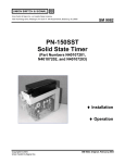
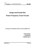
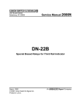
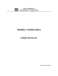
Union Switch & Signal Inc., an Ansaldo Signal company
1000 Technology Drive, Pittsburgh, PA 15219 ● 645 Russell Street, Batesburg, SC 29006
SM 9488
ECC Chaining Modules
Input Isolation Module
Bipolar Output Isolation Module
US&S Part No.
N34800901
N34801201
♦ Installation
♦ Maintenance
Copyright © 2006
Union Switch & Signal Inc.
Original
June 2006
Proprietary Notice
This document and its contents are the property of Union Switch & Signal Inc. (hereinafter
US&S). This document has been furnished to you on the following conditions: no right or
license under any patents or any other proprietary right in respect of this document or its
content is given or waived in supplying this document. This document and its contents are
not to be used or treated in any manner inconsistent with the rights of US&S, or to its
detriment, and are not to be copied, reproduced, disclosed to others, or transferred without the
prior written consent of US&S.
Important Notice
US&S constantly strives to improve our products and keep our customers apprised of changes
in technology. Following the recommendations contained in the attached service manual will
provide our customers with optimum operational reliability. The data contained herein purports
solely to describe the product, and does not create any warranties.
Within the scope of the attached manual, it is impossible to take into account every eventuality
that may arise with technical equipment in service. Please consult your local US&S Account
Executive in the event of any irregularities with our product.
We expressly disclaim liability resulting from any improper handling or use of our equipment,
even if these instructions contain no specific indication in this respect. We strongly recommend
that only approved US&S spare parts be used as replacements.
SM 9488, Original, June 2006
i
Revision History
Revision History
ii
Rev.
Date
Nature of Revision
Original
June 2006
Initial Issue of manual.
SM 9488, Original, June 2006
Table of Contents
Table of Contents
1
Introduction............................................................................................................................................................... 1-1
1.1
Description......................................................................................................................................... 1-1
1.1.1 Input Isolation Module ............................................................................................................... 1-1
1.1.2 Bipolar Output Isolation Module ................................................................................................ 1-3
2
Specifications ........................................................................................................................................................... 2-1
2.1
Input Isolation Module ....................................................................................................................... 2-1
2.1.1 Electrical Isolation ..................................................................................................................... 2-2
2.2
Bipolar Output Isolation Module ........................................................................................................ 2-2
2.2.1 Electrical Isolation ..................................................................................................................... 2-3
2.3
Environmental.................................................................................................................................... 2-3
3
Installation................................................................................................................................................................. 3-1
3.1
Input Isolation Module ....................................................................................................................... 3-1
3.2
Isolation Modules Wired for Chaining Indication Signals .................................................................. 3-2
4
Maintenance.............................................................................................................................................................. 4-1
5
Troubleshooting....................................................................................................................................................... 5-1
5.1
Troubleshooting the Input Isolation Module ...................................................................................... 5-1
5.2
Troubleshooting the Bipolar Output Isolation Module ....................................................................... 5-1
6
Technical Support.................................................................................................................................................... 6-1
List of Figures
Figure 1-1
Figure 1-2
Figure 1-3
Figure 1-4
Figure 3-1
Figure 3-2
Figure 3-3
-
Input Isolation Module .................................................................................................................. 1-1
Input Isolation Module Wiring and Dimensions ............................................................................ 1-3
Bipolar Output Isolation Module ................................................................................................... 1-4
Bipolar Output Isolation Module Wiring and Dimensions............................................................. 1-5
Inputs Wired as Two Unipolar Inputs. .......................................................................................... 3-1
Inputs Wired as a Single Bipolar Input. ........................................................................................ 3-2
Block Diagram Showing Typical Application for ECC Chaining
Using the Input Isolation and Bipolar Output Isolation Modules .............................................. 3-3
Figure 3-4 - An Input Isolation Module and a Bipolar Output Isolation Module
Wired for ECC Chaining of Indication Signals. ........................................................................ 3-4
List of Tables
Table 1-1
Table 1-2
Table 2-1
Table 2-2
Table 2-3
-
Input Isolation Module Screw Terminal Assignment ..................................................................... 1-2
Bipolar Output Isolation Module Screw Terminal Assignment ...................................................... 1-5
Approximate Output Voltages........................................................................................................ 2-1
Approximate Input Impedances..................................................................................................... 2-2
Approximate Output Voltage.......................................................................................................... 2-3
SM 9488, Original, June 2006
iii
Table of Contents
iv
SM 9488, Original, June 2006
Introduction
1
Introduction
This manual covers the Input Isolation Module (N34800901) (Figure 1-1) and the Bipolar Output
Isolation Module. (N34801201) (Figure 1-3) used for isolating external battery and chaining of the
electronic circuit controllers (ECC) of the M-3 and M-23 style switch machine indication circuits.
These two modules are considered vital when used in an application where the input is a vital signal.
The modules cannot deliver an output without this vital signal.
1.1
Description
There are two circuit boards in each 22.5 mm wide, DIN rail mountable module (see Figure 1-2 and
Figure 1-4). All connections to the module are accomplished using screw terminations and keyed plug
connectors. Two separate screw terminals are provided for each electrical connection on the modules.
There are two yellow LEDs on the front edge of each module to indicate the states of the circuit
outputs.
1.1.1
Input Isolation Module
The Input Isolation Module (N34800901) (Figure 1-1) performs two separate functions. In its simplest
application it provides a stand alone component that can isolate an external battery source. When used
in conjunction with the Bipolar Output Isolation Module the unit can drive an ECC conditional power
supply for switch machine indications.
Figure 1-1 - Input Isolation Module
SM 9488, Original, June 2006
1-1
Introduction
This Input Isolation Module is similar in operation to other US&S Isolation Modules; however, instead
of being driven from a Microlok II OUT16 board, this module is driven from an external battery
source. In addition, the module provides increased surge protection on the front end using multiple
stages of MOV’s, inductors, and tranzorbs.
Each input and output on the Input Isolation Module has two separate connections (Figure 1-2). The
+INPUT #1 is applied to connectors 1 and 2; the –INPUT #1 is applied to connectors 3 and 4. Table
1-1 lists the individual screw connections for each input and output terminal. The input to this module
can be set up as two separate unipolar inputs or as a single bipolar input (Section 3.1).
Connections to the module are made with four plug-in screw connectors. There are 16 screw
connections which will accommodate wire size from AWG 24 to AWG 12 with two screw terminals
for each connection. The plug-in connectors are individually keyed for easy replacement. When
assembled in the module the terminal numbers on the plug-in connectors should be sequential – 1
through 8 at the top of the module and 9 through 16 at the bottom of the module.
OUT #1 and OUT #2 are yellow LED indications of the status of the output. When voltage is applied
to the INPUT #1 terminals, OUT #1 LED will light and output power will be available at the OUTPUT
#1 terminals. In the same manner, when voltage is applied to the INPUT #2 terminals, OUT #2 LED
will light and output power will be available at the OUTPUT #2 terminals.
Table 1-1 - Input Isolation Module Screw Terminal Assignment
Screw Terminal
Description
+ INPUT #1
- INPUT #1
+ OUTPUT #1
- OUTPUT #1
1-2
Screw Terminal
Number
1
2
3
4
5
6
7
8
Screw Terminal
Description
+ INPUT #2
- INPUT #2
+ OUTPUT #2
- OUTPUT #2
Screw Terminal
Number
9
10
11
12
13
14
15
16
SM 9488, Original, June 2006
Introduction
4.507"
114.5mm
- OUTPUT #1
+ OUTPUT #1
SCREW TERMINAL PLUG-IN
CONNECTORS 1-8
- INPUT #1
+ INPUT #1
1.771"
45mm
1
2
3
+
INPUT #1
4
5
6
7
8
+
OUTPUT #1
OUT #1
INPUT ISOLATION
MODULE
3.897"
99mm
OUT #2
INPUT #2
+
OUTPUT #2
+
9 10 11 12 13 14 15 16
+ INPUT #2
- INPUT #2
SCREW TERMINAL PLUG-IN
CONNECTORS 9-16
+ OUTPUT #2
- OUTPUT #2
Figure 1-2 - Input Isolation Module Wiring and Dimensions
1.1.2
Bipolar Output Isolation Module
The Bipolar Output Isolation Module (N34801201) (Figure 1-3) is used in combination with the Input
Isolation Module as an isolating amplifier stage to drive multiple ECC conditional power supply
circuits. Currently switch machines equipped with ECC’s are not well suited to connect the indication
circuits of more than two machines in series, contrary to their mechanical counterparts. This is
primarily because indication output circuits are linear amplifiers with an efficiency in the order of
30%. With mechanical controllers the circuits are completed through electrical contacts with virtually
no limit as to how many machines can be connected in series.
When more than two ECC indication circuits are cascaded, the first ECC sees a load that appears to be
a series string of four machines. To overcome this problem, an isolation amplifier is connected
between the second and third ECC in a four-machine configuration, or to connect two isolation
amplifiers between the second and third ECC (Figure 3-3) and between the 4th and 5th ECC in a sixmachine configuration.
Connections to the module are made with four plug-in screw connectors. There are 16 screw
connections which will accommodate wire size from AWG 24 to AWG 12 with two screw terminals
SM 9488, Original, June 2006
1-3
Introduction
Figure 1-3 - Bipolar Output Isolation Module
for each connection. The plug-in connectors are individually keyed for easy replacement. When
assembled in the module the terminal numbers on the plug-in connectors should be sequential – 1
through 8 at the top of the module and 9 through 16 at the bottom of the module.
Each input and output on the Bipolar Output Isolation Module has two separate connections (Figure
1-4). Table 1-1 lists the individual screw connections for each input and output.
OUT #1 and OUT #2 are yellow LEDs that indication the status of the output. When voltage is
applied to the INPUT #1 terminals (+ on connectors 1, 2 and – on connectors 3, 4), the OUT #1 LED
will light and output power (-/+) will be available on BIPOLAR OUTPUT screw terminals (connectors
5, 6 will be – and 7, 8 will be +). When voltage is applied to the INPUT #2 terminals (+ on connector
9, 10 and – on 11, 12); OUT #2 LED will light and output power (+/-) will be available on BIPOLAR
OUTPUT screw terminals (connectors 5, 6 will be + and the output on connectors 7, 8).
A battery must be applied to the BATTERY INPUT (+ on connector 13, 14 and – on connector 15, 16)
for the module to work properly. However only power applied to INPUT # 1 or INPUT #2 connectors
will light an LED or switch on the OUTPUT.
CAUTION
Do not apply power simultaneously to both inputs; damage may
occur to the Bipolar Output Isolation Module under these conditions.
1-4
SM 9488, Original, June 2006
Introduction
Figure 1-4 - Bipolar Output Isolation Module Wiring and Dimensions
Table 1-2 - Bipolar Output Isolation Module Screw Terminal Assignment
Screw Terminal
Description
+ INPUT #1
- INPUT #1
Screw Terminal
Number
1
2
3
4
-/+ BIPOLAR
OUTPUT
5
+/- BIPOLAR
OUTPUT
7
6
8
Screw Terminal
Description
+ INPUT #2
- INPUT #2
+ BATTERY INPUT
- BATTERY INPUT
Screw Terminal
Number
9
10
11
12
13
14
15
16
.
SM 9488, Original, June 2006
1-5
Introduction
1-6
SM 9488, Original, June 2006
Specifications
2
Specifications
2.1
Input Isolation Module
•
Connections - The input circuit may be connected as two individual isolated unipolar circuits
or a single bipolar input circuit (Figure 3-1 and Figure 3-2).
•
Input Battery Range - 9.8VDC to 16.2VDC for the circuit to be energized.
•
Load - Each circuit will drive loads having 400 ohms impedance or higher.
•
Output Voltage - Dependent on load and voltage at the input. Table 2-1 shows the
approximate output voltages with loads of 400, 1000, and 2000 ohms over the operating input
voltage range.
•
Input Source - The input circuits are connected to an external battery source. Surge protection
must be used with low voltage arresters line to line and high voltage arresters line to ground.
Line to Line: USGA low voltage blue arresters N451552-0101.
Line to Ground: USGA high voltage red arresters N451552-0201.
•
Input Impedance - The input impedance is dependent on the load connected to the input
module output. Table 2-2 shows the approximate input impedance as a function of the load
connected to the output.
•
Short Circuit Protection - The Input Isolation Module will withstand a continuous short circuit
condition without sustaining damage.
Table 2-1 - Approximate Output Voltages
Input
Voltage*
Output Voltage*
Output Voltage*
with 1000-Ohm
Output Voltage*
with 2000-Ohm
Load (VDC)
Load (VDC)
(VDC)
with 400-Ohm
Load (VDC)
9.80
9.95
10.00
10.50
10.00
10.30
10.80
10.90
11.00
11.55
12.10
12.20
12.00
12.65
13.20
13.45
13.00
13.85
14.45
14.65
14.00
15.00
15.60
15.90
15.00
16.25
16.90
17.15
16.00
17.35
18.10
18.35
16.20
17.75
18.45
18.70
* Voltages are +/- 5%.
SM 9488, Original, June 2006
2-1
Specifications
Table 2-2 - Approximate Input Impedances
2.1.1
Load Impedance
Input Impedance
Open Circuit Output
550 Ohms
400-Ohm Load
190 Ohms
1000-Ohm Load
310 Ohms
2000-Ohm Load
400 Ohms
Bipolar Output Isolation Module
280 Ohms
Electrical Isolation
The module is isolated between the input and output and between circuit #1 and circuit #2 for up to
2000 Vrms.
2.2
•
Bipolar Output Isolation Module
Connections - There are two non-isolated input circuits in the module with a single isolated
bipolar output drive.
CAUTION
Do not apply power simultaneously to both inputs; damage may
occur to the Bipolar Output Isolation Module under these conditions.
•
Input Voltage Range - 9.8VDC to 16.2VDC.
•
Battery Input Range - 9.8VDC to 16.2VDC. This input must be protected with a battery line
surge protection device.
•
Load - Each circuit will drive loads having 200 ohms impedance or higher.
•
Output Voltage - Table 2-3 shows the approximate voltages of the output with loads of 400,
1000, and 2000 ohms over the operating battery and input voltage range.
•
Output Source - The output circuit is connected to an external ECC and must used low
voltage arresters line to line and high voltage arresters line to ground.
Line to Line: USGA low voltage blue arresters N451552-0101.
Line to Ground: USGA high voltage red arresters N451552-0201.
•
2-2
Short Circuit Protection - The Bipolar Output Isolation Module will withstand continuous
short circuit condition without sustaining damage.
SM 9488, Original, June 2006
Specifications
Table 2-3 - Approximate Output Voltage
Battery
Voltage
Input
Voltage
Output Voltage* Output Voltage*
with 200-Ohm
with 1000-Ohm
Output Voltage*
with 2000 Ohm
(VDC)
(VDC)
Load (VDC)
Load (VDC)
Load (VDC)
9.80
9.80
14.00
14.38
14.46
10.00
10.00
14.03
14.39
14.48
11.00
11.00
14.06
14.40
14.48
12.00
12.00
14.07
14.41
14.49
13.00
13.00
14.08
14.42
14.50
14.00
14.00
14.08
14.42
14.50
15.00
15.00
14.09
14.42
14.50
16.00
16.00
14.09
14.42
14.50
16.20
16.20
14.09
14.43
14.50
* The voltages are +/- 5%.
2.2.1
Electrical Isolation
The module is isolated between the inputs and the bipolar output and the battery input and the bipolar
output to a voltage level of 2000 Vrms. Battery input is common with both module inputs.
2.3
•
Environmental
Temperature Range - –40 C to +70 C
SM 9488, Original, June 2006
2-3
Specifications
2-4
SM 9488, Original, June 2006
Installation
3
Installation
3.1
Input Isolation Module
The Input Isolation Module can be used anywhere that the battery coming in from an external source
needs to be isolated and the current demands of the output are less than 1.5 watts.
The Input Isolation Module can be set up with two unipolar inputs (Figure 3-1) or with a single bipolar
input (Figure 3-2).
Figure 3-1 - Inputs Wired as Two Unipolar Inputs.
SM 9488, Original, June 2006
3-1
Installation
Figure 3-2 - Inputs Wired as a Single Bipolar Input.
When the input to this module is connected to a remote battery source (not inside the same equipment
house), the inputs must be protected with the standard lightning arrester configuration. This consists
of a low voltage arrester line to line (USGA low voltage blue arresters N451552-0101) with high
voltage arresters from each line to ground (USGA high voltage red arresters N451552-0201).
3.2
Isolation Modules Wired for Chaining Indication Signals
As shown in Figure 3-3 and Figure 3-4, ECC Chaining modules can be wired together to provide an
amplifier for the indication circuit for multiple ECC controlled switch machines.
The Input Isolation Module and Bipolar Output Isolation Module are wired for ECC chaining of the
NORMAL and REVERSE indications. The Input Isolation Module is wired as bipolar or unipolar
inputs with the outputs wired to the inputs of the Bipolar Output Isolation Module.
When energizing the Bipolar Output Isolation Module, the output reverses polarity depending on
which input is energized. With INPUT #1 energized, pins 5 and 6 will be – and pins 7 and 8 will be +.
With INPUT #2 energized, pins 5 and 6 will be + and pins 7 and 8 will be -.
3-2
SM 9488, Original, June 2006
Installation
Multiple ECC Machines with indication circuits
*
*
Both Modules together form
an Isolation Amplifier
B12
B12
N12
N12
*
(+)
B12 N12
Battery
(+)
Bi-Polar
Output
N in
(-)
B12
N12
2nd ECC
1st ECC
N in
(-)
15,16
*
Bi-Polar
Output
5,6
1,2
3,4
7,8
3,4
5,6
9,10
13,14 9,10
11,12
15,16 11,12
*
Bi-Polar
Output
7,8
(+)
R in
(-)
(+)
R in
(-)
1,2
13,14
Input
Isolation
Module
Bipolar
Output
Isolation
Module
*
*
3rd ECC
4th ECC
B12
B12
N12
*
(+)
N in
(-)
(+)
R in
(-)
Bi-Polar
Output
N12
*
(+)
N in
(-)
(+)
R in
(-)
Bi-Polar
Output
Two 400 ohm relays
Indicates Wiring
* Line Loss
Resistance is not to exceed 10 ohms in any of the leads connecting
any of the ECC units or chaining modules.
Figure 3-3 - Block Diagram Showing Typical Application for ECC Chaining Using the
Input Isolation and Bipolar Output Isolation Modules
CAUTION
Do not apply power simultaneously to both inputs; damage may
occur to the Bipolar Output Isolation Module under these conditions.
When the input to the Bipolar Output Isolation Module is connected to a remote battery source (not
inside the same equipment house), the inputs must be protected with the standard lightning arrester
configuration. This consists of a low voltage arrester line to line (USGA low voltage blue arresters
N451552-0101) with high voltage arresters from each line to ground (USGA high voltage red arresters
N451552-0201).
Local battery connections to the Bipolar Output Isolation Module must be protected with a secondary
surge protection device such as one of the USSP modules.
SM 9488, Original, June 2006
3-3
Installation
Note
When driving relays, arrestors are not necessary.
Figure 3-4 - An Input Isolation Module and a Bipolar Output Isolation Module Wired
for ECC Chaining of Indication Signals.
3-4
SM 9488, Original, June 2006
Maintenance
4
Maintenance
There is no routine maintenance required on the Input or Bipolar Output Isolation Modules.
In the unlikely event that a module will need replaced, just replace the entire module on the DIN rail
and ensure that the connections are properly made before applying power to the module.
Note
Prior to attempting to replace these modules, disconnect the
power to the module in accordance with standard railroad
procedures.
SM 9488, Original, June 2006
4-1
Maintenance
4-2
SM 9488, Original, June 2006
Troubleshooting
5
Troubleshooting
If a module fails, ensure that all of the connections to the module are tight and verify that there is no
trouble with the power inputs. If this does not solve the problem, please contact the US&S RAIL
Team (Section 6).
5.1
Troubleshooting the Input Isolation Module
If the LED does not light and there is no output voltage proceed as follows.
1. Ensure that the screw terminals are tight and plugged into the correct slot.
2. Ensure that the wire is stripped back to at least 3/8”.
3. Check the input voltage and the polarity on the input terminals, the voltage must be between
9.80 to 16.20VDC. The polarity of the inputs should be as follows:
Input #1 - + on terminals 1, 2 and – on terminals 3, 4.
Input #2 - + on terminals 9, 10 and – on terminals 11, 12.
4. Check for a shorted output by removing plug terminals or wiring. If the LED lights, check for
shorted output. With the input voltage at or greater than 9.80VDC the output will be at or
greater that 9.80VDC. Verify the polarity on the output terminal. The polarity should be as
follows.
Output #1 - + on terminals 5, 6 and – on terminals 7, 8.
Output #2 - + on terminals 13, 14 and – on terminals 15, 16.
5. Replace the module if the everything checked above is correct and the LED still does not light
or the in no output voltage.
5.2
Troubleshooting the Bipolar Output Isolation Module
If the LED does not light and there is no output voltage proceed as follows.
1.
Ensure that the screw terminals are tight and plugged into the correct slot.
2. Ensure that the wire is stripped back to at least 3/8”.
3. Check the input voltage and the polarity on the input terminals, the voltage must be between
9.8 to 16.2VDC:
Input #1 - + on terminals 1, 2 and – on terminals 3, 4.
Input #2 - + on terminals 9, 10 and – on terminals 11, 12.
4. Check for a battery voltage input; it must be between 9.80 and 16.20VDC
SM 9488, Original, June 2006
5-1
Troubleshooting
Battery - + on terminals 13, 14 and – on terminals 15, 16.
5 Check for a shorted output by removing the plug terminals or wiring. If the LED lights, check
for a shorted output. With the input voltage at or greater than 9.80VDC the output will be at or
greater that 9.80VDC.
6. With Input #1 ON - (+ on terminals 1, 2 and – on terminals 3, 4) output terminals 5, 6 will be and 7, 8 will be +.
7. With Input #2 ON - (+ on terminals 9, 10 and – on terminals 11, 12) output terminals 5, 6 will
be + and 7, 8 will be -.
CAUTION
Do not apply power simultaneously to both inputs; damage may
occur to the Bipolar Output Isolation Module under these conditions.
8. Replace the module if the everything checked above is correct and the LED still does not light
or the in no output voltage.
5-2
SM 9488, Original, June 2006
Technical Support
6
Technical Support
The Rapid Action Information Link Team (RAIL Team) is a group of experienced product and
application engineers ready to assist you to resolve any technical issues concerning this product.
Contact the RAIL Team at 1-800-652-7276 or by e-mail at [email protected].
SM 9488, Original, June 2006
6-1
Technical Support
6-2
SM 9488, Original, June 2006