1
~
@
ItIIOTOROLA
INC.
~..
-.'"
@
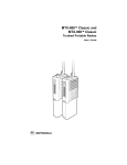
MT1000'
VEHICULAR
ADAPTER
INSTRUCTION
-::,,~.
MANUAL
~.
:"',,""
"
. <~~.-:..,
.,.
:(.,
/c
~://-,
.(--.'
('~ -"
~1~t~~ ~~
'"
..
c-::=
- '.:'"
';-....
". ~
.'
, .
-{>
,; , - .c..:.
'-" '.
".
".,-
.;
~,,~ ;:~,.
..:.; ,;'
'..
':..'.:' -:-
,.
,"
'",.,
.i
.'
MT1000@
VEHICULARADAPTER
CONTENTS
PAGE
SECTION
FOREWORD
SPECIFICATIONS
MODEL CHART
inside front cover
ij
ii
DESCRIPTION
1. GEN ERAl .....................................................................................................................................
.
2.
CONSOLE
3.
EXTERNAL 12-WATT SPEAKER..................................................................................................
"""""""""""""""""""""""""""""""""""""""""""
4.
MOBilE
5 .
ROO
MICROPHONE
FT 0 PAN
TEN
....
"""""'"
"'"
.......
N A . . . .. . . . .. . . . .. . .. . . . . . . . . . .. . . . . . . . . . . . . . . . . . . .. . . .. .. . .. .. . . . . . . . . . . .. . .. . . . .. . . . .. . . . .. .. . .. .. . .. .. .. .. . . .. . . .. .
INSTAllATION
1.
INSTAllATION PLANNING
2. CONSOLE INSTAllATION ..
3. MICROPHONE BRACKET INSTAllATION
4. 12-WATT SPEAKER INSTAllATION
5. ANTENNA INSTAllATION..
6.
CONSOLE
7.
ANTI-SKID BRAKING PRECAUTIONS
CABLING.
8.
INSTAllATION
...
..,
,
...
...
""0 0" 0"
CHECKOUT..
""""""'"
...
... """"0
.........
.....
.......
.....
"'0" ................
""0"""""'0
'0'
0""'0""""""'"
""""""""""""""""""""""'"
............
"
o................
2
3
3
3
4
4
5
6
THEORY OF OPERATION
1.
G EN ERAl
2.
CIRCUIT
. 00"""""""""""""""""""""""""
o
DESCRIPTION.
~.. 0" o.o.0"""""""
00'" 00""""""'"
0"""""""""""""""
0""'"
"""""""""""""
MAINTENANCE
1. PREVENTIVE MAINTENANCE
0""""""""""""""'"
......................
2. CORRECTIVE MAlNTENANCE ....................................................................................................
REPLACEMENT PARTS ORDERING
:
,'..
RELATED PUBLICATIONS AVAilABLE SEPARATELY
MT1000 VHF Service Manual
MT1000 UHF Service ManuaL
0""""""'"
'0"""""""""""
0"0"""""""""'"
MT1 000 Theory/Maintenance
Operating Instructions
Manual
0""
0"
0"""""""""'"
0"""""""""""'"
0"""
0 .....
o'
.....
0""""""""""""""""""""""""""""
0'"
0""""""""""""""'"
0""""""""""""""""""""'"
0"'"
0"
0 0""
0"
0""""""""
Reducing Noise Interference in Mobile Radios.........................................................................
7
7
10
10
inside back coV'er
68P81061 C40
68P81061C45
68P81061C50
68P81062C70
68P81109E33
@ , Motorola, MT1000, HT600, HT600E, HT800, MTX-800, MTX-900, Handie-Talkie, and Private-Line are trademarks of Motorola Inc.
@ 1989 by Motorola Inc., Portable Products Division,
8000 W. Sunrise Blvd., Ft. Lauderdale, FL 33322-9934
Printed in U.S.A. 4/89, All Rights Reserved
Instruction Manual
68P81062C75-0
SPECIFICATIONS
One MT1000, HT600, MTX-800,* MTX-900, HT800, or HT600E radio.
265.5x158.5x83mm (10.43"x6.24"x3.26")
CAPACITY:
DIMENSIONS (LxHxW):
WEIGHT:
1.70kg (3.76Ibs)
13.8Vdc (11Vdc min.-16Vdc max.) negative ground
CHARGED BATTERY
DISCHARGED BATTERY
200mA
600mA
300mA
750mA
1.2A
1.2A
(without portable radio)
NOMINAL INPUT VOLTAGE:
CURRENT DRAIN:
Radio OFF:
Radio ON:
Transmit:
CHARGE RATE:
Three hours (Rapid Charge) and Sixteen hours
(Standard Charge) Batteries
50 Ohms
ANTENNA INPUT IMPEDANCE:
AUDIO OUTPUT:
500mW with Internal Speaker
12W with External Speaker**
(at less than 5% distortion)
* MTX-800 radios have no external rf hookup.
** Optional
Specifications
,
MODEL NUMBER'
. ",
rr-EM NO~
X
X
X
X
X
A
A
A
A
A
A
A
A
X
X
X
X
X
X
A
A
A
A
A
A
A
A
'.'"
! :...
'
"c;,,:..'
,.
'
:
Basic Package
Enhanced Package
NTN 1048A
NTN 1050A
xI
,
.' ','DES'CR'IPti0~{
subject to change without notice.
NTN5612A
NTN5613A
NSN6054A
NTN5489A
HMN1035A
HMN1037A
HMN1056A
TAD6111A
TAD6112A
TAD6113A
TAD6114A
RAE4012ARB
RAE4014ARB
RAE4015ARB
RAE4016ARB
'
I
,'))ESCRIPTI,ON~
KEY X = ITEM INCLUDED
A = ALTERNATE ITEM SUPPLIED; CHOICE DEPENDS UPON FREQUENCY
ii
. .',
Charging Console (Basic)
ChargingcConsole (Enhanced
12-Watt Speaker
Speaker Adapter
Palm Mobile Mitrophone
DTMF Palm Microphone
Mini Mobile Microphone
Antenna, 1/4 Wave Rooftop (136-144 MHz)
Antenna, 1/4 Wave Rooftop (144-152 MHz)
Antenna, 1/4 Wave Rooftop (152-162 MHz)
Antenna, 1/4 Wave Rooftop (162-174 MHz)
Antenna, 5dB Gain Rooftop (406-420 MHz)
Antenna, 5dB Gain Rooftop (445-470 MHz)
Antenna, 5dB Gain Rooftop (470-494 MHz)
Antenna, 5dB Gain Rooftop (494-512 MHz)
MAEPF-20088-0
DESCRIPTION
1. GENERAL
3. EXTERNAL 12-WATT SPEAKER
The Basic Motorola Mobile Radio Adapter (MVA) is
a vehicular mounted unit used to adapt MT1000@,
HT600TM, MTX-800TM (no external rf hookup),
MTX-900TM, MTX-800TM, HT800TM, or HT600ETM
Handie-TalkieQ!J
portable FM two-way radios for mobile
operation. The vehicular adapter system consists of a
console, an external 12-watt speaker/amplifier, a handheld mobile microphone, a rooftop antenna, mounting
hardware, and cables.
The NSN6054A 12-watt speaker provides 12-watts
of audio ouput power for use in high noise level
environments. The audio level of the speaker can be
adjusted from the console's panel.
When the radio is inserted into the console pocket
for vehicular operation, the resulting combination acts
as a mobile radio, with the following functions
occurring automatically:
The vehicular adapter's external antenna is
connected to the radio, and the radio's internal
antenna is disconnected.
The vehicular adapter's mobile microphone is
connected to the radio, and the radio's internal
microphone is disconnected.
The console's charging circuits are connected to
the radio to charge the radio's battery.
The radio's audio output is connected to the
external 12-watt speaker/amplifier, and the radio's
internal speaker is disconnected.
2. CONSOLE
The NTN5612A (Basic) console is the vehicular
adapter's central unit. The Basic console includes
three LEOs on the front control panel, palm
microphone, 12-watt external speaker, mounting
hardware, and power cables. When the MT1000 or
MTX-900 radio is loaded into place, the MVA
overrides the portable's volume control. All MVA
consoles have a key lock located below the radio
pocket.
When the radio is loaded in the console, the
combined radio/console operates as a mobile two-way
radio. The radio must have a battery attached when it
is inserted into the console; this battery will be
automatically charged when the radio is inserted. A
key lock is provided on the console to minimize theft
when the vehicle is left unattended. Appropriate
mounting hardware is provided with the console to
facilitate mounting at any suitable location.
4.
MOBILE MICROPHONE
Three different types of mobile microphones are
available for the MVA: the HMN1056A compact
microphone, the HMN1035A palm microphone, and
the HMN1037A DTMF palm microphone.
The microphones are palm-type, weatherproof,
cartridge
microphones,
with
transistorized
preamplifiers as an integral part of the cartridge. Each
microphone is equipped with a push-to-talk (PTT)
switch on the side, has a coiled cord, and an 8-pin
connector which plugs into a jack on the left side of the
console. Mounting hardware is provided as part of the
console package.
5. ROOFTOP ANTENNA
To enable the vehicular adapter to function as a
mobile vehicular radio, an external rooftop antenna
must be ordered from C&E Parts. This antenna is cut
to correspond to the frequency band of the radio used'
with the vehicular adapter. Refer to the MODEL
CHART for specific antenna model numbers and
frequencies.
INSTAllATION
1.
INSTAllATION PLANNING
a. General
Before starting the installation, determine the
location of the console, microphone, and 12-watt
speaker. Also, check the mounting penetrations
required. On most vehicles, it is necessary to penetrate
the firewall to reach the battery. Check the opposite
side of the firewallfor cable clearance before drilling
holes, and protect the cable where it passes through
the firewall by using the supplied grommets or other
similar protective measures. Because of the wide
variations in vehicle design, these instructions may be
modified to suit each particular installation
requirement.
A properly installed MVAwillminimizeservice calls
and equipment downtime. Consider the following
guidelines when planning the installation:
The console should be mounted to provide 12inches of clearance in front of the console for inserting
and removing the radio. A 4-inch clearance at the rear
and left side of the console is necessary for connection
of power, microphone, antenna, and speaker cables; a
2.5 inch clearance is required above the vents on the
top of the console. Consider accessibility to the
controls by the operator. When possible, mount the
console on the floor near the center of the vehicle.
c. Microphone Bracket location
When possible, mount the microphone bracket on
the dash near the left side of the console. The location
should be within easy reach of the operator, and it
should be convenient to remove and replace the
microphone without interfering with any of the vehicle
controls.
1
DO use all mounting holes provided.
DO use lockwashers where provided
DO ensure that unit cables are not placed under
stress, are not weathered, and are not subjected to
damage due to engine heat.
DO follow proper A+ and A- connections.
DO tape all splices securely.
DON'T attach the units to any part of the vehicle
that is not rigidor is subject to excessive vibration.
DON'T install units in areas where rain or snow
can easily get into them, such as next to a vehicle
window which may be left open.
DON'T dress cables over sharp edges that could
cause wear or tearing of cable insulation.
DON'T install the units in locations where they
might interfere with the vehicle operator or
operating controls.
DON'Tinstallthe unitswhere they will be difficult
for the operator to reach.
CAUTION ~
Do not attach the microphone
the housing of the sole.
mounting bracket to
d.
Speaker location
Select a location for the speaker that will be
neither dangerous to the operator nor damaging to the
speaker. A trunnion bracket is provided for mounting
the speaker. The speaker is normally hung under the
dash near the right side of the console; however, the
trunnion bracket permits mounting the speaker against
a wall or other vertical surface, if desired.
e. Antenna location
Compfete antenna installation instructions are
supplied with each antenna ordered. Refer to those
instructions for all information pertaining to the
antenna. Also, refer to the SAFETY INFORMATION
paragraph in the FOREWORD of this manual for
additional information.
f. Battery Connections
IWARNING~
For vehicles with electronic anti-skid braking
systems, refer to the "Anti-Skid
Braking
Precautions" section of this manual.
b. Console location
NOTE
If possible, avoid mounting the console in a vertical
position. This will minimize the danger of foreign
substances being dropped or spilled into the
console pocket.
2
Determine the best cable route from the rear of the
console to the vehicle battery through the engine
firewall. The best route should include the shortest
path to the battery terminals, yet provide the cable with
protection from engine heat. Be sure the supplied
grommet or similar protective measure is used
wherever a cable must pass through a hole in a metal
panel, such as a firewall. The power cables must be
routed in a way that protects them from being pinched
or crushed. For best results, connect the positive and
negative leads directly to the battery terminals.
2.
3.
CONSOLE INSTAllATION
Referring to Figure 1, crimp the S-hook (supplied
with the mounting hardware) to the microphone cable
approximately 1.5 inches to 2 inches from the
connector end. When hooked to the baseplate, this
prevents inadvertent damage to the cable connections
when using the microphone. Care should be taken to
prevent cutting into the cable jacket when installing the
S-hook.
Referring to Figure 1, install the console using the
following procedure, or modify the procedure as
necessary to conform to the vehicle type:
a. Using the trunnion bracket as a template, drill the
mounting holes, and mount the bracket with the
hardware supplied. If the trunnion bracket is to be
mounted on the floor or vehicle console, bend the
tabs on the bracket to conform to the shape of the
floor or vehicle console (see Figure 1).
Referring to Figure 2, use the microphone
mounting bracket as a template and drill two 1/8-inch
holes. Attach the microphone bracket to the mounting
surface with the two self-tapping screws provided. Be
sure to leave sufficient room above the bracket for
insertion and removal of the microphone.
b. Position the console onto the trunnion bracket so
that the knurled fittings of the console and trunnion
bracket mesh together.
c.
MICROPHONE BRACKET INSTAllATION
Place the lockwashers on the Allen-head screws,
then insert the screws through the trunnion bracket
and screw them into the console. Since the
console will have to be removed later to connect
the cables, do not tighten the screws at this time.
When connecting the DTMF palm microphone to
the MVA, press
the"1"
tone and tune the
microphone's adjustable DTMF level to 60% of the
radio's system deviation (i.e. 3kHz on a radio with
5kHz maximum system deviation or 1.5kHz for
MTX-900 radio).
DASH
MOUNT
tOR
AEPF-19494-Q
.
FLOOR
HOUNT
Figure 2. Microphone
4.
Bracket Installation Detail
12-WATT SPEAKER INSTAllATION
The 12-watt speaker includes a trunnion bracket, a
hanger bracket, and a wall-mount bracket, permitting
the speaker to be mounted in a variety of ways.
MOUNTI '~G 6fJM "L
~
,
CUTAU,'>OF~'.
CONSOLEOR
FLOOR MOUNT
~,
1. NO 10-16x3/4 SELF'TAPPING SCREW
2. 5/16-24 x 3/8 ALLEN HEAD SCREW
3. 5/16 LOCKWASHER
(1
".
"",
CEPF-19493-0
'
'.
~
.
The trunnion bracket is used to permanently mount
the speaker on the dashboard or accessible
firewall areas, while permitting the speaker to be
tilted to a desired angle.
The hanger bracket permits temporary mounting,
such as on an automobile window. The speaker
must be removed from the trunnion bracket to use
the hanger bracket.
Figure 1. Console Installation Detail
3
DASHBOARD
HANGER BRACKET
PHILLIPS
MACHINE SCREW
6-32
X 1/4"
(SEE
TRUNNION
(HOLE
"'0
(
BRACKET
I
SIZEJO.157IN.DIA.
~
~.,
~
~
'RAm'
,
I
r Il l
,l
A
~
W
'
OR
WINDOW MOUNTING
DETAIL
11.'.
:
.
WALLMOUNT
BEND TAB TO CONFORM
TO FLOOR OR CONSOLE
FOR MOUNTING
FIREWALL
II~'
~~~~~rT-
NOTE)
ALL MOUNT
-
SELF TAPPING
SCREW
SIZE)
O.lOIIN.DIA
.
".'
",
ET D"
ETAI~~
BRACK
NOTE:
THE REAR COVER OF THE 12W SPEAKER MUST BE
TEMPORARILY REMOVED TO MOUNT THE HANGER BRACKET.
USE TWO 6-32XI/4"
PHILLIPS MACHINE SCREWS AND
TWO TINNERMAN NUTS.
~/
!..-IO-16XS/8"
l(HOLE
.
//
/
1l11f
"."//~I
~ /./
0
')
.
6-20X1/2
SELF-TAPPING
SCREWS
BEPF-t9496-0
MOUNTING BRACKET DETAIL
Figure 3. 12- Watt Speaker Installation Detail
The wall-mount bracket can be used for
permanent mounting if the trunnion bracket is too
large to fit in the desired area. In this case, the
trunnion bracket is removed, and the speaker is
attached to the wall-mount bracket by the hanger
bracket.
Referring to Figure 3 for installation
perform the following procedure:
only. The console should be cabled using the following
procedure:
ICAUTION Remove the 5-ampere fuse from the power cable
(red wire) before proceeding.
information,
NOTE
Due to space restrictions, it may be necessary to
remove the console before making connections to
the connectors at the back of the console. If this is
the case, make the connections and re-mount the
a. Using the trunnion bracket as a template, drillthe
necessary mounting holes and secure the bracket
with the self-tapping screws provided.
\
a.
b. Position the 12-watt speaker onto the trunnion
bracket, and secure it using the wing screws
pr()vided.
5.
ANTENNA INSTAllATION
Install the antenna and antenna cable as outlined
in the installation instructions supplied with the
antenna. Pertinent information on frequency matching,
and mounting details are also provided with each
antenna.
Refer to Figures 4 and 5 before routing or
connecting any console cable. As shown in Figure 5,
the console is used with a negative ground system
4
Route the main power cable through the firewall
and into the battery com~artment. Use an existing
opening or, if necessary, drill a 3/4-inch hole
through the firewall. Insert the grommet provided
with the mounting kit into the hole to prevent
damage to the power cable.
b. Connect the black lead to the chassis of the
vehicle.
ICAUTION -
NOTE.
The rf jack, on the MVA console is a mini-UHF jack,
and must be mated with either a mini-UHF plug
(P3) or a UHF-to-mini-UHF adapter (Motorola part
number 5880367822).
6. CONSOLE CABLING
consolebeforereplacingthe 5-ampfuse.
It is not good practice to connect the black lead to
the negative (-) battery terminal; the MVAcould be
damaged ifthere were a malfunction in the vehicle's
electrical system.
c. Connect the red lead to the positive ( + ) battery
terminal. Ensure that the plug and jack in the wire
are connected firmly together.
d.
Connect the yellow lead to the switched side of the
ignition circuit.
e. Dress the cable so that it does not obstruct any
vehicle controls or touch any hot or moving parts
of the engine.
f.
any irregular audible sounds, or by any change in the
performance of the braking system itself.
NOTE
During procedure steps (1) through (6), however,
none of the above conditions should be observed.
Connect power cable jack J7 to console plug P7.
Attach the strain-relief hook to the console.
g. Connect speaker cable plug P6 to console jack J6,
applying three in. lb. of torque to each screw.
Attach the strain-relief hook to the console.
(1) With the car gear selector in NEUTRAL or PARK,
your foot off the brake pedal, and the engine
running at a fast idle, key (turn the carrier on and
off) the transmitter with and without modulation.
Refer to the note above.
h. Connect external antenna cable plug.
i.
Connect microphone cable plug P4 to console jack
J4. Attach the strain-relief hook to the console.
j.
Make certain that no radio is installed in the
console, then replace the 5-amp fuse.
7. ANTI-SKID BRAKING PRECAUTIONS
a. General
The following transmitter installation suggestions
and test procedures are recommended for vehicles
with electronic anti-skid braking systems.
b. Installation Suggestions
Determine the location of the braking modulator
box in the vehicle. This box is located in the trunk of
Chrysler Corporation cars, and either in the trunk or
under the dash in General Motors and Ford
Corporation automobiles. A service manual may be
helpful in finding the location of the braking modulator
box.
Install the MVA console in accordance with the
following recommended guidelines:
If the braking modulator box is mounted in the right
side of the vehicle, mount the console on the left
side to give as much space as possible between
Jhe box and the console. If the box is mounted on
the left side of the vehicle, mount the console on
the right side.
Use the shortest practical length of Motorola
coaxial cable.
Mount the antenna on the side of the car trunk
opposite from the braking modulator box.
Route all cables along the side of the vehicle
opposite from the braking modulator box.
DO NOT operate the transmitter while the vehicle
is in motion with the trunk lid open.
(2) Repeat step (1) with your foot gently pressing the
brake pedal. Refer to the note above.)
(3) When performing this step, allow at least two car
lengths of clear area in front of the vehicle while it
is stationary. Press your foot on the brake pedal
with just enough pressure to keep the vehicle from
moving. Put the car in a forward gear with the
engine running at a fast idle, then key the
transmitter with and without modulation.
IWARNING
~
Disruption of the anti-skid braking system may
cause the vehicle to move forward in addition to the
lights and audible sounds mentioned above.
(4) Drive at a moderate speed (15-25 mph) with your
foot off the brake pedal, and have an assistant key
the transmitter with and without modulation. Refer
to the above warning.
(5) Repeat step (4) with your foot lightly on the brake
pedal to turn off the brake lights. Refer to the
above warning.
I
WARNING'
Severe disruption of the electronic anti-skid braking
system may cause loss of control of the vehicle in
steps (6). (7). and (8).
(6)
Increase
the vehicle speed to 25-30 mph.
Decelerate slowly and come to a stop. As you are
doing this, have an assistant key the transmitter
with and without modulation. Refer to the above
warning.
(7) While making abrupt stops from 20 mph, have an
assistant key the transmitter with and without
modulation. Refer to the above warning.
c. Test Procedure
This test is divided to cover several different types
of interference. Disturbance of the electronic anti-skid
device can usually be detected in several different
ways in the vehicle's braking system: by the lights, by
(8) If no interference or disruption is noticed, repeat
step (7), making abrupt stops from 30 mph. Refer
to the above warning.
5
If no malfunctions are observed in performing the
above steps, it can be assumed that no apparent
problem exists and the car can be released to the
Also, check all mechanical parts for tight and secure
mounting.
customer.
Check for proper operation of the console,
microphone, speaker, and radio as described in the
operating
instructions,
Motorola
publication
68P81061C35.
.
If any of the above steps results in a brake
malfunction, contact the car manufacturer's service
department as soon as possible, and remove the radio
from the vehicle. DO NOT complete the installation.
8. INSTAllATION CHECKOUT
a. General
After completing the installation of the vehicular
adapter, check all electrical wiring for tight connections.
6
NOTE
If alternator or other vehicular noise is present in
the received signal or in the transmission, refer to
"Reducing Noise Interference in Mobile Two-Way
Radios," Motorola publication 68P81109E33. This
publication may be ordered separately from
Motorola Communications Sector National Parts
Department.
THEORY OF OPERATION
1. GENERAL
The MVA is compatible with HT600, MTX900,
MT1000, HT800 and HT600E FMtwo-way radios. The
resulting combination of the console and portable radio
gives the same or better performance as a standard
mobile system. The MTX800 radio can also be placed
in the MVA;however, the MTX800does not have the
abilityto port external rf.
Connection between the radio battery and the
console is made through the charger contact block
(mountedon the printedcircuitboard)inthe rear of the
radio pocket. The contacts on this block and the
associated circuitry automatically charge the portable
radio battery.
Connection between the console and the portable
radio functions is made through the portable radio
control top universal contacts. When the portable radio
is inserted intothe console pocketand pushedin, the
radio universal contacts are automatically engaged by
the MVA pogo pins, and all basic portable radio
functions are available to the console.
On the basic model MVA(NTN5612A), all basic
portable radio controls remain with the radio except for
the volume control when the 12W speaker option
is used.
The mobile microphone and antenna are also
automaticallyconnectedto the portableradiowhen it is
inserted into the console pocket.
/?'
2. CIRCUITDESCRIPTION
a. General (Refer to the schematic diagram)
The console is powered directly from the vehicle
battery and through the vehicle ignition switch. The
console consists of battery charging, PAC. RT
interface, switching regulation, microphone and audio
PA interface capabilities.
b. Ignition and PAC. RT Interface
Turning the ignition switch on causes the car
ignitionvoltage to be supplied at J7 pin 2. Ifa radio is
in the MVA,ground will be present at J5 pin 5. This
groundwill providea biasingpath which turns 022 on.
When 022 is on, 024 is turned on and switches the
relay (K1). The relay supplies the MVAwith power for
all circuitry.
When the PAC. RT switch (81) is turned off, J6
pin 9 is grounded and the PAC. RT is disabled. When
the PAC. RT switch is on and a radio is in the MVA,
023 is saturated, J6 pin 9 is low,and the PAC. RT is
still disabled. When the radio is removed from the
MVAand the PAC. RT switch is on, 023 is off and J6
pin9 is high, and the PAC .RT is enabled.
c. Switching Regulator
Due to the variation of the vehicle's battery voltage
of 13.8V:t20%, the switching regulator is required to
step up the vehicle's voltage to the constant 16.5V:t5%
required by the charging circuit to provide a constant
rate of charge. The switching regulator operates at
40KHz and the input voltage is stepped up to 16.5V.
The output capacitors (C8 to C10) reduce the ripple
voltage to less than 100mV for an 800mA load at
25° C.
d. Current Regulator
The charger is receptive to two different charge
rates: A three hour fast charge (OAC) and a sixteen
hour slow charge (0.1C). Features for dead battery
operation during transmit (PTT), with constant 800mA
charge rate and extra 70mA charging ifthe radio is on,
is incorporated.
The charging current is controlled by a current
regulator with negative feedback. The current regulator
is comprised of transistor circuits 02 thru 06,
U11,U12, a differential amplifier (U3C), and single
inputamplifier(U3D).Undernormalconditions,05 and
U12-C are in saturation (ON)giving a rapid charge rate
of OAoC. When the radio is loaded, the momentary
increase in charging current through R19 (1Q) results
in an increase in differentialamplifieroutput (pin 8) and
input to the single input amplifier (pin 13). Its output
drops and the base drive of 02 and 03 is reduced.
Therefore,the chargingcurrentdrops and maintainsa
constant charge rate according to the sensing resistors
of the battery.
Diodes CR3, CR4, transistor 04 and resistor R15
provide for a constant current input of transistor 05,
turning on 05, independent of battery terminal voltage
and charge rate. Together with 06, this constant
current source can be switched off for trickle-charging
by switching off 06, 04, and 05. With 05 turned off,
R16 ,R154 and R153 are added in the charging path.
7
The following chart lists the three different battery capacities, RC's, and rapid charging current and trickle
charging current.
BAlTERY
CAPACITY
500
900
950
RC
Q
5.6K
3.3K
3.3K
CHARGINGCURRENT(mA)
RAPIDWITHRADIO
ON
OFF
320
430
430
At dead battery operation, the console provides a
constant 800mA to the radio for transmitting. Pressing
the PTT switch causes 027 to turn off, and U12 pins 7
and 8, to go low. This switches off U12C and the
charging current is no longer controlled by RC, but is
controlled by R36 instead.
e. Battery Sense Detect
With no battery in the charger, the voltage at U3-B
pin 6 is approximately 9.6V, holding the output of U3B pin 7 low. When the radio is loaded in the console,
U12-C conducts. Voltage at U3-B pin 6 drops to
approximately 1AV. This drop in voltage results in a
high output at U3-B pin 7 turning on 012 and
charging LED CR28.
f.
TemperatureWindow and
Bistable Multivibrator
Comparators U4-B, U4-C, and U4-0 sense the RT
line and set the cold and hot sides of the temperature
window respectively. The cold side temperature is
below 8° C while the hot side temperature is above
41°C. If the temperature rises above 60°C, the output
of U4-B goes low cutting off charging completely.
Temperature sensing is through a thermistor (RT),
and its resistance is converted to voltage and
compared with preset voltages of each comparator.
During normal operation (8°C to 41°C), the output
at U4-D pin 14 is high turning on 05 and the charging
rate is OAC. If the temperature falls below 8°C the
output at U4-D pin 14 is low, turning off 06,04, and
05, charging at 0.1C.
As the battery charges, the temperature of the
battery increases causing RT resistance drops. As the
temperature increases and exceeds 41°C, the output
of U4-C goes from high to low, causing the output of
U4-A to go low and turning off 06, 04, and 05; the
MVA is now in slow charge (0.1°C). Once the battery
temperature goes above 41°, the rate of charging will
latch at 0.1C with the help of 030, 031, 032 and
associated circuitry. This prevents a fully charged
battery going back to rapid charge as its temperature
drops. The sudden low output at U4-A results in a low
8
250
360
360
CHARGINGCURRENT(mA)
TRICKLEWITHRADIO
ON
OFF
130
160
160
62
90
90
output at U5-C pin 2 changing the LEDs (CR28
&CR29) from red to green indicating complete state
of charge. This charging rate will continue as long as
the temperature of the battery remains below 60°C. If
the battery temperature exceeds 60 degrees the output
of U4-B goes low, and the pass transistor (02) turns off
and all charging stops. U4-B going low also results in
the enabling of the oscillator and the LEOs will flash.
Due to the linearity of RC with charging current,
resistor R96 is added to compensate for 900mAH and
950mAH battery capacity. Resistors R98 and R100
provide an extra 70mA charging current (rapid and
slow) when the radio is on.
g. Oscillator
The oscillator circuit turns the green and yellow
LEDs on and off (flashing) indicating that a problem
(shorted or open cells, shorted terminals) is detected
with the battery or the contacts when the output of the
short circuit detector circuit, U5-C pin 13, or the battery
open circuit detector, U5-0 pin 14, goes low. This pulls
pin 7 of U5-B lower than pin 6, and the output of the
oscillator U5-B pin1 changes from high to low. Hence,
C38 discharges through R80 and R81 until the voltage
falls"below the output at pin 7 of U5-B and toggles the
alP again. The output of the oscillator flips back and
forth and turns the green and yellow LEDs on and off.
If a problem occurs during the charge complete cycle,
only the yellow LED will flash.
h. Battery (O/C) Open Circuit Detector
During normal operation, pin 9 of U5-0 is higher
than pin 8 of U5-D unless an open circuited battery is
detected (RC present but no charging current). The
low impedance of RC causes the differential
operational amplifier output to go low, pulling pin 9 of
U5-D lower than pin 8 of U5-D and, thereby, pulling the
output low. This low output turns the oscillator on,
triggering the green and yellow LEOs which causes
them to flash.
i.
Shorted Cells and Short Circuit Detect
This circuit compares the voltage at the battery
terminals with a preset reference voltage of 4.0V. As
long as the terminal voltage goes low, the charging
.
current is cut off completely thru U8-D. This circuit also
activates the oscillator that flashes the green and
yellow LEOs.
Capacitor C37 (100uF) is used to hold the output
high when the console is powered on and is also used
to time the response of the short circuit detect.
Dynamic Voltage Clamp
As long as the voltage at the battery terminals
remains below 15V, the output of U3-A is held high.
When the battery voltage exceeds 15V, the voltage at
pin 2 U3-A is greater than the voltage at pin 3 U3-A.
This causes the output of U3-A to go low and reduces
the base drive for 02, thus limiting the terminal
voltage to 15V. This prevents over voltage loads and
(protects the radio from high voltage damage.
j.
I.
Microphone and AUdio PA Interface
An external microphone and audio amplifier are
connected to the MVA through Telco and DB-25
connectors, respectively. Audio path selection is made
by adjusting switches 81 and 82 (white switches
located on back of console). The MVA is shipped
standard with the 12W PA, and both 81 and 82 should
be in the dQwnposition. For MT1000 and MTX radios,
the volume control is remoted to the MVA. For HT600
radios, either the radio or MVA volume control can be
used. For best results, the HT600 radio should be
adjusted to 3/4 maximum volume when placed into the
console. All volume adjustments should be made using
the MVA volume control. The chart below shows other
methods for routing audio.
METHOD I
12 W AUDIO
k. Radio ON/OFF Sensing Circuitry
The MVA contains sensing circuitry detecting
whether the radio is on or off. When the radio is on,
the MVA supplies an extra 70 mA of charging current
to the battery to compensate for the current drawn by
the radio in the standby mode. When the radio is on,
B+ voltage (J5 pin 3) and Busy (J5 pin 3) go high.
When the busy line goes high, the output of U13-A will
go high. Option B+ and/or the output of l:J'13-A pull
U12 pins 3 and 4 low. This causes U12 pins 1 and 2 to
go high and supply bias to U11 pin 13. This switches
R98 into the circuit and modifies the charging current
to supply the extra 70 mA.
RADIO AUDIO
S1 POSITION
1
S2 POSITION
DOWN
DOWN
UP
UP
.
Receive audio from the radio (J5 pin 8 and 2)
passes through volume pot R109 and attenuator
resistors R110, R111 and R142 to the 12 watt audio
PA (J6 pins 20 and 21). The 12 W squelch is
controlled via transistors 020 and 021. When the
radio unsquelches, 020 turns on and 021 turns off.
This causes the PA squelch line to go high (J6 pin 5).
The microph.one receives its bias voltage from the
MVA's 12 volt regulator through R127 and R128 to J4
pin 5. The microphone signal comes from J4 pin 5
through C103 and R126 to the radio via J5 pin 1.
~
l--
.
-J
9
I.
Microphone and Audio PA Interface
An external microphone and audio amplifier are
connected to the MVA through Telco and OB-25
connectors, respectively. Audio path selection is made
by adjusting switches 81 and 82 (white switches
located on back of console). The MVA is shipped
standard with the 12W PA, and both 81 and 82 should
be in the dQwn position. For MT1000 and MTX radios,
the volume control is remoted to the MVA. For HT600
radios, either the radio or MVA volume control can be
used. For best results, the HT600 radio should be
adjusted to 3/4 maximum volume when placed into the
console. All volume adjustments should be made using
the MVA volume control. The chart below shows other
methods for routing audio.
current is cut off completely thru U8-0. This circuit also
activates the oscillator that flashes the green and
yellow LEOs.
Capacitor C37 (100uF) is used to hold the output
high when the console is powered on and is also used
to time the response of the short circuit detect.
j.
Dynamic Voltage Clamp
As long as the voltage at the battery terminals
remains below 15V, the output of U3-A is held high.
When the battery voltage exceeds 15V, the voltage at
pin 2 U3-A is greater than the voltage at pin 3 U3-A.
This causes the output of U3-A to go low and reduces
the base drive for 02, thus limiting the terminal
voltage to 15V. This prevents over voltage loads and
(protects the radio from high voltage damage.
I
METHOD
12 W AUDIO
k. Radio ON/OFF Sensing Circuitry
The MVA contains sensing circuitry detecting
whether the radio is on or off. When the radio is on,
the MVA supplies an extra 70 mA of charging current
to the battery to compensate for the current drawn by
the radio in the standby mode. When the radio is on,
B+ voltage (J5 pin 3) and Busy (J5 pin 3) go high.
When the busy line goes high, the output of U13-A will
go high. Option B+ and/or the output of Ij13-A pull
U12 pins 3 and 4 low. This causes U12 pins 1 and 2 to
go high and supply bias to U11 pin 13. This switches
R98 into the circuit and modifies the charging current
to supply the extra 70 mA.
RADIO AUDIO
I
S1 POSITION
DOWN
UP
I
S2 POSITION
DOWN
UP
]
Receive audio from the radio (J5 pin 8 and 2)
passes through volume pot R109 and attenuator
resistors R110, R111 and R142 to the 12 watt audio
PA (J6 pins 20 and 21). The 12 W squelch is
controlled via transistors 020 and 021. When the
radio unsquelches, 020 turns on and 021 turns off.
This causes the PA squelch line to go high (J6 pin 5).
The microphone receives its bias voltage from the
MVA's 12 volt regulator through R127 and R128 to J4
pin 5. The microphone signal comes from J4 pin 5
through C103 and R126 to the radio via J5 pin 1.
"-
9
MAINTENANCE
1. PREVENTIVE MAINTENANCE
a. Periodic Inspections
Slow degradation of equipment performance, if left
uncorrected, can lead to costly equipment downtime
and repair. Preventive maintenance (PM) differs from
corrective maintenance in that minor equipment
operating deficiencies can be corrected before
breakdown occurs. Periodic and systematic PM
inspection schedules should be set up to keep the
equipment operational and failure free. The frequency
of PM schedules will be determined
by the
environment in which the equipment is being used.
..
c...
The periodic inspections should include:
Visual inspection of cables for frayed or oxidized
leads.
Ensuring that battery connections are free from
oxidation or corrosion.
. Checking the external rooftop antenna for clean
and rust-free mounting.
Checking for tight connection of the console-toantenna cable connecto~s.
Checking the system ground lead (black) for clean
and proper electrical contact.
Checking all jack and plug connections for
tightness and good electrical pin contact. Pins
should be visually checked for wear.
Checking for loose components.
Checking
compqnent
assemblies
and mechanical
assemblies for tight and secure installation. The
. majority of MVA failures is directly related to poor
installation.
Inspecting all mounting brackets and associated
mounting screws for secure and tight mounting.
Checking
for overh-eated
or discolored
components.
Checking for proper (13.8Vdc) vehicular alternator
charging. Vehicular voltage can vary from as low
as 12.9Vdc to as high as 18Vdc without being
evident to the operator; however, it can affect MVA
operation.
b. Cleaning
Procedures
In areas of high dust or salt conditions, periodically
check the mechanical 'operation of the console's
battery contacts. If contact "movement requires
excessive effort, clean any dust or salt deposits from
the moving parts as described below. Cleaning may be
accomplished by performing the following procedure:
(1) Remove the console from the vehicle and place it
rightside-up on a flat working surface. The working
surface should offer protection from scratching to
the console's surfaces.
10
(2) Referring to the "Disassembly/Reassembly
Procedures" (paragraph d) in the "CORRECTIVE
MAINTENANCE"
section of this manual,
disassemble the unit for cleaning.
(3) Clean the external surfaces of the console using
the recommended cleaning agent. These surfaces
should be cleaned whenever a periodic visual
inspection reveals the presence of excessive dust,
grease, and/or grime.
The only recommended agent for cleaning the
internal and external plastic MVA surfaces is a
0.5% solution of a mild dishwashing detergent in
water (one teaspoon of detergent per gallon of
water).
ICAUTION
~
The effects of certain chemicals and their vapors
can be harmful to some types of plastics. Aerosol
sprays, tuner cleaners, and other such chemicals
should be avoided.
(4) The internal circuit boards and components should
ordinarily be cleaned when the console must be
disassembled for servicing or repair. The only
factory recommended liquid for cleaning the circuit
boards and their components is isopropyl alcohol
(70% by volume).
NOTE
When the MVA is used under adverse marine
conditions, the circuit board must be cleaned of salt
deposits at least twice a year.
Isopropyl alcohol may be applied-Jwith a stiff, nonmetallic, short-bristled
brush to dislodge
embedded or caked-on materials located in hardto-reach areas. The brush stroke should direct the
dislodged material out and away from the inside of
the console.
Alcohol is a high-wetting liquid and can carry
contamination
into unwanted places if an
excessive quantity is used. Make sure that the
controls ,are not soaked with the liquid. Upon
completion of the cleaning process, use a soft,
absorbent, lintless cloth to dry the area.
NOTE
Always use a fresh supply of alcohol and a clean
container to prevent comtamination by dissolved
material from previous usage.
(5) Reassemble
the
console,
disassembly procedure.
reversing
the
2. CORRECTIVE MAINTENANCE
a. Introduction
Efficient corrective maintenance requires an
orderly and logical troubleshooting procedure for
localizing malfunctions in the MVA's internal or
external circuits. Troubleshooting and repair will be
greatly simplified by becoming familiar with the overall
MVA and radio operation.
This section provides detailed information required
to isolate malfunctions to the MVA's internal or external
circuits. The troubleshooting chart at the end of this
section provides information on possible circuit
failures,
related
symptoms,
and suspected
malfunctioning stages.
Generally it may be assumed that, if the MVA is
totally inoperative, the vehicle's battery is completely
discharged, the fuse is blown, or the power lead is
opened. However, if the MVA is partially operative, it
may be assumed that the batteries are serviceable
and that one or more internal or external functional
MVA circuits are defective or marginal. Using
diagrams, the troubleshooting chart, the voltage table,
and deductive creasoning, the qefective circuit may
readily be found.
To further aid in analyzing the symptoms and
,
possible causes of the malfunction,check: rf power
output using an in-Ifne wattmeter, audio deviation, and
current drain. Once the general problem area of the
MVA is identified, careful use of a dc voltmeter,
ohmmeter, and/or oscilloscope should help isolate. the
problem to a defective component.
b. Test Equipment and Service Aids
The "RECOMMENDED TEST EQUIPMENT" chart
lists the test equipment recommended to properly
service the MVA. Refer to the service' manual for the
associated radio for the recommended radio test
equipment. For field servicing, jhe vehicle's battery.is
an adequate power source. Battery-operated test
equipment is recommended when available.
RECOMMENDED TEST EQUIPMENT
R-2001,R-2002,
or R-2200
NAME
CHARACTERISTICS
ServiceMonitor
-----
APPLICATION
Audio
circuit,
testing ,frequency!
deviation,
See your Motorola csalesrepresentative for aid in
ordering test equipment. The sales representative will
analyze your requirements and help you select the
latest available equipment and service aids to suit your
individual needs.
(1) MAV-PACK 3 (VID-952)
The VID-952 Motorola Video Visual Package
(MAV-PACK) is a video tape training program on
leadless component repair techniques. This VHS
format video cassette and supplemental literature
describe the removal and replacement of leadle~s
components
using the following
specialized
equipment:
RRX-4033 Laurier Hot Gas Bonder
RPX-4234A Regulator and Hardware Kit
0180386A62 Heated Tweezers
RSX-1002 Desoldering Station
RSX-1008 Weller Soldering Station
This MAV-PACK is strongly recommended for
technicians who intend to servic;:e this and other
Motorola products using leadless components. This
VHS videotape is in standard half-inch format. This
MAV-PACK, as well as others, is available from:
Motorola C&E, Inc.
National Service Training Center
1300 N. Plum Grove Road
Schaumburg, Illinois 60195
c. Troubleshooting
Refer to the troubleshooting and voltage charts at
the back of this section to isolate a malfunction to a
defective circuit. Follow the flow through the chart,
check each observation, and answer each question.
As an aid in understandirng the operation and
functioning of a particular circuit, refer to the
appropriate
paragraphs
in the "THEORY OF
OPERATION" section of this manual.
If a circuit board must be tested, it may be
necessary to remove it from the chassis and test it
outside of the enclosure. In this case, leave all wires
connected to the board, and use care to protect the
board from being accidentally shorted out. Use heat
sinks with insulators on transistor Q2 while the board
is removed from the chassis.
power output.
S-1347
DC Power
Supply
0-20Vdc,
0-5Amps;
Power supply for
bench testing.
current limited
S-1053
AC Voltmeter
1mV to 300mV
RMS, -72dB to
+52dB; 10MQ
input impedance
R-1 028
Solid-state
---- -
Digital
Multimeter
Waveform
measurements
Oscilloscope
R-1001
Audio voltage
measurements
Highinput
impedance
DCvoltage,
resistance
measurements
11
(f) Repeat Step (e) for the rear guide pins.
d. Console Disa~sembly
NOTE
The Universal Connector pins can be individually
replaced without disassembling the console.
Grasp the pin with a pair of tweezers and pull it
out towards the rear of the console.
(a) Unlock the MVA, remove the radio from the pocket
and disconnect
all cables (including
the
microphone). Remove the key from the lock and
place the console on a flat surface.
(b) Referring to Fi.gure 4, insert a small flat-bladed
screwdriver into the two top housing catches at the
rear of the housing. Disengage these catches one
at a time while applying pressure to separate the
top and bottom housings. These catches can only
be reached from the underside of the console.
(c) kift the top housing from the rear of the MVA so
the front hooks in the bottom housing near the
volume knob can slide out of their mating slots.
Set the top housing to the side away from the
pocket since there is still a flex circuit connection
to the top housing.
(d) With thumb and forefinger, grasp the top edges of
C0nnector J3 (white), and lift up to disconnect the
LED circuit fleX. The connector will move upward
about 1/8," but does not) separate from the PCB
fully. The flex circuit can now be pulled out of
the connector.
(e) Position the pocket housing at its highest position.
Unsnap the front two guide pins of the pocket
housing from the guideways by bending the left
guideway and pushing the pocket housing
upwards.
"
(g) Unhook the two helical springs from the baseplate
catches.
NOTE
Whenever
the pocket is removed from the
assembly ( steps e thru g) ,it is recommended that
all four cam shafts (mate to the pins on the pocket)
on the bottom housing be wiped clean to remove
any foreign material. To accomplish this, use a dry
cotton swab.
(h) Pull the volume pot knob out of its shaft.
(i) Disconnect the universal connector flex from its
connector (J5) using the same procedure as
explained in Step (d).
(j) Unsnap the power transistor clip.
(k) Referring to Figure 5, and using the small
screwdriver,unsnap the five snap catches holding
the main PCB. The board should be pulled directly
upwards to allow the microphone connector to
slide from its mating grooves. The main PCB is
still attached to the bottom housing by the ribbon
cable connected to the volume pot board. The
main board can be flipped forward to access the
underside without removing the volume pot board.
(I) To remove the volume pot board, unsnap it from
the bottom housing by lifting the totwo catches.
(m) Referring to Figure 6, and using
a small
screwdriver, unsnap the six catches that hold the
baseplate and the bottom housing together.
(n) Lift the plastic bottom housing away from the
bas~plate.
;
LOCATION FOR
SCREWDRIVER
~
;
0
~~::>
(~::>
~,
~
.:::-.~~),
0
MAEPF-20018-0
12
Figure 4. Disengaging the Two Catches
;
Figure 5. Top View of PCB
MAEPF-20019-0
high voltage charges. Damage can be latent, resulting
in failures occurring weeks or months later. Therefore,
special preC(autionsmust be taken to prevent device
damage during disassembly, troubleshooting, and
repair. The following handling precautions are
mandatory for CMOS circuits, and are especially
important in low humidity conditions.
~
~d
~]I ~~
(1) All CMOS devices must be stored or transported in
conductive material so that all exposed leads are
shorted together. CMOS devices must not be
inserted into conventional plastic "snow" or plastic
trays of the type that are used for storage or
transportation of other semiconductor devices.
0
0
~
~@~
MAEPF-20020-0
Figure 6. Top View of Bottom Housing
--
(0) The universal connector housing can only be
removed after the bottom housing is removed from
the baseplate. Locate the two snap features (about
1/2" on either side of the contact pins). Using the
small screwdriver, push the snaps down and slide
the connector housing and lock bracket toward the
rear of the cons0le. The bracket will only slide
about 172" back and then the connector housing
can be lifted out of the bracket. Unsnap the
universal connector header and flex assembly
from the connector housing.
ICAUTION
(2) All CMOS devices must be placed on a grounded
bench surface and the technicians must ground
themselves prior to handling the devices. This is
done most effectively by having the technician wear
a conductive wrist strap in series with a 1Oak-ohm
resistor to ground.
(3) Do not wear nylon clothing while handling CMOS
circuits.
(4) Do not insert or remove CMOS devices with power
applied. Check all power supplies to be used for
testing CMOS devices, and be certain that there
are no voltage transients present.
(5) When straightening CMOS device leads, provide
ground straps for the apparatus used.
(6) Use a grounded soldering iron.
~
Be careful not to damage any of the components
on the flex Qircuit on the bottom housing snaps as
it is pulled out.
(p) To remove the lock assembly, slide the bracket
toward the rear, out of the slots in the housing.
Note the position of the torsion spring so it can be
reassembled correctly. Lift up on the rear end of
the rod and unsnap it from the bottom housing.
The lock assembly can then slide out through the
front of the housing.
e. Console Reassembly
Reassemble the. console by reversing the
disassembly procedure. Be careful to completely snap
all of the snaps that hold the bottom housing to the
baseplate and the main PCB to the bottom housing.
f. Safe Handling of CMOS Devices
Complementary
metal-oxide
semiconductor
(CMOS) devices are used in the MVA. While the
attributes of CMOS are many, their characteristics
make them susceptible to damage by electrostatic or
(7) All power must be turned off in a system before
printed circuit boards contq)ning CMOS devices are
.~. inserted, removed, or soldered.
g. Parts Replacement and Substitution
When defective parts or components must be
replaced, identical parts should be used. If the identical
replacement part is not locally available, check the
electrical and exploded view parts lists for the correct
Motorola part number. Order the part from the nearest
Motorola Communications Parts office as listed under
"Replacement Parts Ordering" on the inside back cover
of this manual.
If, for any reason, substitutions must be made,
reinstall the exact replacement part as soon as
possible to ensure optimum performance. The
substituted
part must have identical electrical
characteristics and must have equal or higher voltage
and current ratings.
If it is necessary to replace any of the transistors
that mate agains1the heat sink fins on the chassis, be
13
sure to form the new transistor's leads like those of
the original part so that the transistor lies flat against
the insulator when clamped by the transistor clip
against the heat sink fins.
unsoldering and removal of parts, which could
damage or weaken other components or the printed
circuit board itself.
(1) Rigid Circuit Boards
h. Soldering
The MVA uses bonded multi-layer printed circuit
boards. Since the inner layers are not accessible,
some special considerations are required when
soldering and unsoldering components. The printed
through holes may interconnect multiple layers of the
printed circuit. Therefore, care should be exercised to
avoid pulling the plated circuit out of the hole. Closely
examine your work for shorts due to solder bridges.
ICAUTION Leadless component technology requires the use
of specialized equipment and procedures for
repair and servicing of the SVA. If you are not
totally familiar with leadless component repair
techniques, it is strongly recommended that you
either defer maintenance to qualified service
personnel and service shops, or take the
recommended video-taped component repair
training program, MAV-PACK 3 (VID-952). This is
of paramount importance as irreparable damage
to the SVA can result from service by
unauthorized persons. Unauthorized attempts to
remove or repair parts may void any existing
warranties or extended performance agreements
with the manufacturer.
(2) Flexible Circuits
The flexible circuits are made from a different
material than the rigid boards, and different
techniques must be used when soldering. Excessive
prolonged heat on the flexible circuit can damage the
material. Avoid excessive heat and excessive
bending. For parts replacement, use the ST-1087
Special care must be taken to be as certain as
Temperature-Controlled Solder Station with a 600 or
possible that a suspected component is actually at
700 degree tip, and use small diameter solder such as
ST-633. The smaller size solder will melt faster and
fault. This special care will eliminate unnecessary
require less heat being applied to the circuit.
POWERDISTRIBUTIONTABLE
024
IGNITION
NO RADIO
INMVA
IGNITION
ON RADIO
INMVA
J7
CR1
U2
U9
02
B
13.8V
PIN1
13.8V
PIN2
13.8V
PIN4
OV
CATH
OV
PIN1
-
PIN3
-
B
-
E
C
11.8V
13.8V
13.8V
OV
13.8V
12V
5V
13.5V
16.8V
16.2V
CHARGER SECTION VOLTAGE MEASUREMENTS
RAPIDCHARGE
(REDLED)
TRICKLECHARGE
06
U3C
C
PIN8
RADIOOFF
020
021
12WSPEAKER
C
C
O.2V 6.02V
SQUELCHED
HI
LO
13V
12WSPEAKER
LO
HI
9.2V
UNSQUELCHED
(COMPLETE)
RADIOON
.
U12
PIN3 PIN4
OV LO
5V
HI
027
PTTSw. PRESSED
PTTSW.PRESSED
C
4.30V
HI
O.2V
LO
LED CIRCUITRY SECTION VOLTAGE MEASUREMENTS
RED LED ON
RAPIDCHARGEBATTERIES,RAPIDCHARGING
GREENLEDOFF
TRICKLECHARGEBATTERIES,STANDARDCHARGING
RED LED OFF
RAPIDCHARGEBATTERYCOMPLETE
U4
U5
Q11
012
PIN1
PIN14
PIN2
C
C
HI
HI
HI
HI
LO
LO
HI
LO
LO
HI
OR
GREEN LED ON
14
LO
EXPLODED
VIEW PARTS LIST
ITEM
MOTOROLA
NUMBER
PARTNUMBER
0102703J05
CEPF-19498
2
3
4
5
6
7
8
0400114169
0383265G05
1505066RO1
3002173JO1
2602328JO1
4205200RO1
01 02701 J42
9
10
11
12
13
14
15
16
17
18
19
20
21
22
23
24
25
26
See Note
0705097RO1
4102146JO1
3702133JO1
4705099RO1
1505069RO1
6402139JO1
1302141JO1
3605096RO1
1302140JO1
1502136JO1
5502147JO1
0105951N79
1505067RO1
3902135JO2
3902137JO1
3902137JO2
0102701J90
27
28
29
30
31
32
33
3802138JO1
1505068RO1
4102155JO1
0102701J38
0702151JO1
1302142JO1
3002301JO4
-0
TPLF-3816-0
DESCRIPTION
I
BRACKET, Trunnion
(includes items 2&3)
LOCKWASHER (2 req'd)
SCREW, Hex Socket (2 req'd)
HOUSING, Top
CABLE, Miniature UHF Assembly
CLIP, Heatsink (2 req'd)
CLIP, Power Transistor
ASSEMBLY, Main PCB (includes
items 6,9,19,24,25 &33)
POT, Volume (R109)
BRACKET, Keylock
SPRING, Keylock
SLEEVE, Friction
ROD, Vibration
HOUSING, Bottom
BASEPLATE
ESCUTCHEON,
Side
KNOB, Keylock
ESCUTCHEON,
Bottom
HOUSING, Charging Contact
KEYLOCK
ASSEMBLY, Knob Volume
HOUSING, U-Connect
CONTACT, U-Connect (13 req'd)
CONTACT, Charging (8 req'd)
CONTACT, Charging (4 req'd)
HEADER ,Flex Assembly
(includes items 5 &23
PIN, Cap (4 req'd)
HOUSING, Pocket
SPRING, Helical Ext. (2 req'd)
ASSEMBLY, Flex Dislay
BRACKET, Housing Top
ESCUTCHEON,
Top
CABLE, Flat Volume
EXPLODED VIEW DIAGRAM
AND PARTS LIST
19
,
Set volume control to
mid range, ignition
switch on, press
monitor button
~/2W
.
Int
audli
Is noise heard from
console or ext spkr?
No I
cheCk if external spkr
I
select,82-1,is d~e
I
IINo
Disable switch
82-1.
I IYes
1/2W
Test Handie- Talkie
8T ART .1
.radio and battery
according to
procedure in manual
Place radio in console
connect power cable
and 1/2W or 12W ext
audio power amplifier
Conn RF wattmeter and
dummy load to rear of
console (load should be
able to dissipate 10' -- "
ext audiol
1) Recheck. radio & btty
2)"Check DC circuitry in
.
console for proper ~harging
operation if btty is discharQed
Check ifext spkr
select, 82-1, is enable
Check if external spkr
select, 82-1, and CVC IINo
sense, 82-2, are selected
ifused
. ,.~,
.:~
,~.
.;.:.
"'.
.'~'
Yes
..::~;.
i.~
.",:,
,J
Check 12W audio
power amplifier
Check. mic'connector
and
.(~;
:~\
.~t
.\1
continuitY to CVC
:~t
Check red LED, check
continuity of mic
conn to universal conn
. .<.
.,
1) Check co~ and conn
2) Check charger ckt if
radio bttyis discharged
Apply a 1KHz signal
of -13dbm between
pin 5 & pin 40fJ1
(m{cconn)
Dekey mobile
microphone,check for
proper charger
operation
.A.
Yes
..Check charger
circuitry
.i;~
,
Check for cOn~nuity of
mlc ~nn to unive~I.
is there
sufficient deviation?
'~r
.
'J'
'..,'
conn and universalflex'
1
to.LiniVe~1 head conn:!
MCEPF-19497-o
J
TROUBLESHOOTING
CHAR'
ELECTRICAL' PARTS. LIST,
REFE~ENCE
SYMBOL
TPLF0.3815-0
C2
03
04
C5
C6
C1
DESCRIPTION
CAPACITOR,
FIxed:
2360561 M71
410f:20%;50V
2160521G37
2113141A29
2113741A49
2160521A11
2113741A21
Not Usec;I
0: 1 uF +80 -20%; 25V
2200pF:t 5%i 25V
15nF:i: 5%; 25V .
pF:t 5%; 25V
1000pP.l:1O%; 25V
----------
23O2159J03
C8,9
C10
C11, 12
C13
C14
C15
C16
C17
C18
C19lhru 22
2360561M70
2362998059
2369561M23
2113740A67
C23,24
211374OA67
C25
C26 thru 30
031
032
C33,34
C35
C36
C37
C38
C39, 40
041
042 thru 46
047
22uF:l:2O%; 16V
.
---------2160521H39
-.- - - - - - - - -
----------
2362998059
1uF:t1O%; 2OV
2360561 M44
NotUsed
100uF:t20%;16Y
4.7i1,F:t10%;16V
----------
2362998D74
- - - .;- - - - 2362998D74
.
2305600P22
NqtUsed
PNP, MMBT-3906
NPN, 5MBT-1001
PNP, MMBT-390
----------
Not Used '
NPN,
PNP.
NPN,
NPN,
NPN,
PNP.
NPN,
PNP,
NPN,
5MBT-1001
MMBT-3906
5MBT-1OO1
945P
5MBT-1001
MMBT-3906
$MBT-1OO1
MMBT-3906
5MBT-1OO1
2113741A45
C102
----------
82pF:t5%;SOV ,
C103
C1O4; 105
C106
2362998D59
2362998D74
2360561 M23
1uf;t1 OOk;20V
4.7uF:t10%; 16V
22uF:i:2O%: 16V
Not Used
4880236E07
4802.191J07
TnlnsienjSUppressor,
MR2525L
Ft Rec;overy.MUR405
TaPe and Reel, IN539t
Rectifier
Rectifier
Hot Carrier,'BAT49
LED, Red
LED,Green
"
06s0076E69
0660076E51
- - - - -'- - - - 0660076A56
1760471A01
0660076A65
0660075l49
Not Used
LI;;D,Red
----------
Not Used
Rectifier
NEltUsed
4805;494004
----------
NotUsed
CR42, 43
4805494004
4805729G29
Rectifier
lED, Green'
J1,2
----------
Rectifier
JACK:
NotUsed
J7
09021;;'&101
O9O2167JO1
0902178JO1
0960113DO1
0902176Jo1
Connector,
Connector,
Connector,
Connector,
Connector,
K1
800216fJO1
RELAY:
9V
24O5452C08
2SO2162JO1
INDUCTOR:
Choke
100uH
ZIFLOK
Modular
ZIFLOK
I;>B25
Modu
----------
R2.
R29,30
R31
R32
R33
R34
0660076A73
R35
R36
R37.38
R39
0660076E69
0660076A42
0660076FO1
1 Meg :1:1%
,1Ok
Not Used
2k
10k
47k
4.1k
0660076A56
0660076A73
0660076A89
0660076A65
(\
----------
;
6.81<:1:1
%
510
1001<:1:1%
Not Used
O66OD76FD3
066007eA76
0660076A81
0660076A89
1201<:1:1%
----------
13k
22k
41k
NotUsed
0660076E77
151<:1:1
%
0660076E81
221<:1:1
%
1Meg
10k
16k :t1%
5.11<:1:1%
1Meg
2Ok:1:1%
0660076825
0660076A73
0660076E78
0660076E66
0660076825
0660076E80
0660076E61
, 0660076B25
0660076A73
0660076801
0660076808
0660076A73
----------
0660076A85
0660076A89
0660076B25
:
Not Used.
82k
----------
R55
R56 thru 58
1={59
R60
R61
R62
R63
R64
R65 .
10
2k
430;2W
4.1k
1k;1I2W
10
82k
1Meg;1%
Hi %;2W
1.5k
10k
4.1k
330
0660076E95
0660076F25
1702166JO1
0660076A53
0660076A73
0660076A65
0660076A37
0660076E95
0660076F25
'.
NotUsed
O66OOi6AO1
R26
R27
R40
R41
R42.
R43
R44
R45,4
R47
R48
R49
R50
R51
R52
R53
R54
1.5k
1/8W
0.47; 2W
6.81<:1:1
%
1.2k:t:1%
1160471A03
0660076AO1
211374OA53
----------
RESISTOR, FIxed: ili:5%;
unless stated
10
16k:i:1%
100k
220
0660076AO1
0660076E78
0660076801
0660076A33
0660076A53
RiO
C101
l2
.
4805128M62
4805128M67
4805128M62
48D5474G42
4805128M62
4805128M67
4805128M62
4805128M67
4805128M62
R11
R12
R13
R.14
R15,16
R17
,R1S
R19
R2O
R21,22
R23
R24
R25
.01uF
33OpF:l:5%;SOV
.O1uF
l1
27
R6
R7'
R8
. R9
DIODE: See Note
.
19
2.2uF; Tant.
22uF:I:20%; 16V
2113741A45
2113740A67
J5
J6
Q'11,12
Not Used
C55, 56
C57 thru 61
C1oo
J4
4805128M67
4805128M62
4805128M67
R1
R2
R3
R4
AS
NotUsed
4.7uF:t10%;16V .
--.-------
4805494Q04
----------
010
024
O251hru
028
029,30
031'
032,33
Not Used
82pF:t5%; SOV
4.7uF:t10%; 16V
Not Used.
2362998D74
----------
07lhru9
.
NPN, MPS650
NPN, 5MBT-1001
4.7uF:i:1O%; 16V
----------
211374OA53
4805746G16
4805494Q04
4805494Q04
4805005R01
4880051 M01
4880051 M02
4880051 M01
4805414G43
4805128M62
020.21
Q22
Q23
NotUsed
33OpF:t5%; SOV
' 82pF:i:5%; SOV
4.7uF:t1Q%; 16V
22uF%2O"lo; 16V .
J3
TRANSISTOR, See Note
MOSFET;IRF521
PNP, TIP32A
'NPN, 945P
PNP, LP733
330pF:t5%
2362998D74
2113740A67
211374OA53
2362998074
2360561 M23
CR39 thru 41
4802197J08
4805708G09
4805474G42
4805474(;f1
Q13
Qj4lhru
.
C50
CR38
01
Q2
03
Q4
Q6
33OpF:t5%; 5OV
NQtUsed
0.-15uF+80-20%; 25V
2360561 M23
CR1
CR2
CR3,4
CR5lhru 7
CR26
CR27
CR28
CR29
CRSO
CR31
CR32
CR33,
CR34lhru 37
Choke
Choke
as
1500uF:l:2O%;25V
560uF:t2O%; 35V
Not !Jsed
47OUFf200k; 35V
1uF:t10%; 2OV Tant.
2302159J02
----------
C48
049
. C51,52
C53
C54
2482723H21.
2405452CO8
MOTOROLA
PARTNUMBER
'.
C1
l3
L4 thru 10
3.31<:1:1%
'
1Meg
10k
100k
2001<
10k
Not Used
33k
41k
1Meg
I
.
.R66
R67'
R68
R69
A70
A71
A72
0660076B17
0660076801
0660076E77
0660076F03
0660076F08
0660076B18
0660076F01
470k'
A73,74
A75
A76
A77
A78
A79
,A8O
R81
A82
R83
'R84
R85
R86
'A87
A88
A89,90
R91
A92
A93
R94 thru 97
R9a'
R99
R1oo
A101
A102
A103
R104
'Rl05
'Al06
A107
Al08
Rl09
A110
,A1l1
R112,113
R114
A15
R116
Rl17
R118
'R119
R120
R121
R122thru 124
R125
R126
R127
'R128
A129
A130
A131
A132,133
Al34
A135,13S"
R137
R138,139
A140
R141
R142
R143
R144
R145
R146
R147
R148,149
A150
A152
153,l54
R155
A156
At'57
R158
'A159
R160thru ,164
0660076A73
0660076807
1Ok
18Ok
S1
S2
0660076801,
1091<
151d:1%
12Ok::1:1
%
200k:t:1%
51Ok
1 00k:f:1 %
1001.<',
15Ok
10k
33k
200k
1Meg
5;6k
1k
.5.k
1Ok
33k
1Ok
3.3k
330
47k
22k
100k
---------Not Used
0660076A75
12k
47k
0660076A89
3.6k
. 0660076A62
.0660076A.S9
47k
0660076A73'
10k
0660076A89
47k
10k
0660076A73
4.7k
0660076A65
47k
0660016AS9
10k
0660076A73;
47k
0660076A89
18O5100Q03
Pot; 25k
lk'l
0660076A49
0660076A73
10k
066007gA49
1k
51k
0660076A90
22k
0660076AS1
0660076A49
1k
lOOk
066007.6801
fSk
066007SA.79
066007SA89
47k
066007SA73
10k
066oo76A25
100
._--------Not Used
0660076A79
16k
0660076A71
S.2k
0660076A29
150
180
Q660076A31 .
0660076A89
4'1k
22k
0660076A81
2k
0660076A56
10k
0660076A732k
066()()76A56
0660076A89
47k
0660076A49
1k
0660076A79
16k
76A37
330
---------NotUsed
0660076A35
270
10k
066007SA73
47k
066007SA89
tOOk
o66OQ7S801
---------Not Used
47k
0660076AS9
10k
. 0660076A73
16k
066Q076A79.
---------. Not Used
10
0660076AO1
16k
0660076A79
100k
,,0660076801
0660076A79
16k
---------Not Used
0660076A73
1Ok
0660076A27
120
0060076805
0660076A73
0660076A85
066007680S
0660076B25
0660076A67
0660076A49
0660076A67
0660076A73
0660076A85
0660076A73
0660076A61
0660076A37
0660076A89
0660076A81
0660076801
4005088P01
4002164;JOl
U1
U2
U3
U4,5
U6
U7,S
,U9
U10
U11,12
U13.
5102198J29
5105469E49
5102198J28
5102198J19'
.,VA1
VR2;3
VA4,5
VFl6
4805129M37
4805129M61
4805129M25
5l0219a.J20
5102l98J26
5102198J2O'
5102198J1'8
5102198J19
,
LM2902D
Quad LM2901 D
Not Used
Diode Array
Voltage Aeg. 5V
[)lode Array
Quad; MMP03904
"
Quad. LM2901 D
DIODE:.See Note
4811058B<?5
Zner;
10V
Zener;
18V
Zener; 5.W
'Zener; 30V
NONRt!:FERENCED'rrEMS
0180743T91
0200115123
, 0300139498
0300139913
2982044J02
,2982607805
3700081057
42OOS93647
4210217A04
3005442TO2
ASSY, Mic. Bracket
NUT, Mounting 10-32 Hex
SCREW, Mounting
1Q-32x5lS" Hex
SCAEW, MountingS-1Sx112
lUG, Ignition
'LUG, Battery
GAOMMET, Rubber
CLAMP, 8-hook
. STRAp, lie
" 'CABLE, Power
NOTE: For optimum performance, order replacement diodeS and transistors
"
by Motorola pan number only.
.
'.
.
SWITCH:
PAC-AT
DIP
ELECTRICAL PARTS LIST
Quad OPAmP;
----------
/)
18
CIRCUIT MOI)ULE: See Note
PwM ; UC2843.
Voltage Aeg:2V; LM340LA
J5
~
)-
II;
'"
) VIEWED FROM SIDE I
--""
Lt, 0EPF ,0009-0
OL - DEPF - 200
16
11-0
CIRCUIT BOARD COMPONENT LAYOUT
, DIAGRAM.
-~ un--
VIEWED
FRON SIDE I
~"---,,,~,--,
I
16
CIRCUIT BOARD COMPONENT
LAYOUT DIAGRAM
J6
NC
G~D
GND
DATA
PA SO
NC
EXT SPKR
SPKR COM
PAC-RT
-1->=!-NC
2>---t
l
,3 >---t---i
4"
5/1
6 )-f-NC
7
8
9 1
RIIO
Ik
1
1
1
I
I
NC
TO
12WATT
SPEAKER
FILTERED A+
TPIO
TPI2
10>+NC
II>-+n
NC 12>+NC
C56
JIOnF
NC 13>+NC
EXT MIC 14; I
EXT PTT 15:
16.5V 16:
BUSY 17:
R111 RII3
10k
Ik
TPI4
TP151--.f-p
RJ9.9f 1
25k
,
QI
NC 18>+NC
NC 19>+NC
PA AUDIOCOM 20; I
PA AUDIO 21'
NC 22>-+-NC
IGN SW+ 23;
FILTERED A+ 24'
C6 -'- R6
1 .47=
I
680pF=
NC 25>-+-NC
UNFILTERED A+
TOJ
VEHICLE I
IGN SW+
HEADLIGHT
GND
BUSY
DATA
MONI TOR
FROM
MICROPHONE
(NCI
J7--"
-1:-'
2:
3'
,
POCKET LIGHT
~~
3: =
1
DATA 4:
BUSY 5:
5V 6:
TO
5V 7:
LED
DISPLAY
TO CR28 8:
BOARD
TO CR29 9:
TO CR30 10
HEADLIGHT 11
5V 12
TO CR28 13
TO CR29 14
_':_J
J5
EXT MIC -1-:-'
EXT SPKR 2
B+ OPTION 3
EXT PTT 4
GND 5
DATA 6
TO
UNIVERSAL EXT SPKR SEL 7
CONNECTOR
SPKR COMM 8
VIA FLEX
BUSY 9
CVC SENSE 107"
l
GND l1
GND 12
I
GND 13
I
14
GND
--_J
a
=
RI60
RI61 RI62 RI63 RI64
=- I
/I 120 120 120 120
IL______---------CR42
I
4)-+
--_J
J4
-1:-'
2'
3>-+-NC
4: I
5:
6:
7:
GND
EXT MIC
EXT PTT
REMOTE POWER
GND 8'
_':_J
J3
---I
GND
GND
B + OPTION
I
I
r
I
120
II
CR43
=
OSCILLATOR
r
'
I
5V
CR27
12V
I
I
I R8S
I IOk
I
I
I
CR34
I
I
I
RI26
8.2k
:
I
I
~~
U5B
GND 6
12
L-
- - -
+ R83
I
_:..._.::. C38
R81
I
I
I
I
- - - -=J
- 4.7uF~ Ik . 1M-
CR35
C61
330pF
t
DYNAMI
C
VOLTAGE
WINDOW
S2
R86
33k
r -1- - - - - - --1-1-- - - I
I
I
I
I
lI -'- - - - ~ - J~ - -.
9
U8D:
6
I
I
I
I
I
I
I
f
5
U8
10
L______-----SIC DETECT
~,
~
CR40
GE9
~~~~~~~~~----------
Q2
CR3
'8" -:jm3'
;O~F~
0tO+15601JFJ;
""
J
BATTERY SENSE DETECT'
r
"'
'
eo
,
I
I
I
I
I!
I
Il i'.:
,U3B
1\
I
I
I
~
I
I
II
7
I
I
-II
r--':'--=
6~2V I
12V
I:
R64
47k
I
",
'
j
"
I
'
"ij$~.:
.
I
I U5D
I
r&7li
ijEl",R: I 14
3 + 9
V+
R67
GND 8
12
lOOk
+C35
R66
R68
I
I
I
I
I
II
I
I
63D81062C76-0
_47Ok
- ISk luF I
1- - --- - -=-- .:.- ..::- _I
BATTERY OIC DETECT
~
SCHEMATIC
DIAGRAM
17
12V'
'-.-'
II
to'
RII5
r;;;:
22dl\iit:
"'"
><
",..
ii;.
RIIO ~ ~R111 RII3
Ik ~ ~ 10k Ik
- ".~'
TPIO.
i
RI7
82k
liV'N
TPI2.
R
1
TPI4. .TPI51-.f-p
02
R~g~r 1
C1+
4 7uF
TPI3.
TPII
RI42
270
I-=
RI
C2 'T'
10 330pF=4:-
l
CR7 I~~~
16.5V
R4
220
TO
!
CR3
7
CR30
R21
10k
6
CIO +
l'
560uF
U1
PWM
3
I=
CR37
C6
R6
680pF -= .47 -=
I
R8
1.2k
R42
22k
VR6
30V
OSCILLATOR
r
-.
'"
I
I
II R85
10k
~::
I
~~
I
I
I
CR34~
U5B
J
GND 6
12
+
C38
I
R83
- 4.7uF~ Ik
L- ---
-
I
II
I
I
I
I
I
12V
_:
R81
14
1M- I
:. - - - _..::J
5V
Ii
3.4
<'
-
47k
+
-
. 14 cr05
I
1'
4.7uF 3}OPil
,
.
Ii II~
P
"
J
.
,_.1
".'.
o'
:t;
.
'
I
f,
I
12 U7 3
~
r;
:
G
9
,011
U7
10 U7 5
13 U7 2
I
I
I
I
I
:
I
14 U7 1 I
R93
R8G
33k
I
11 U7 4 I
I
L
I
I
I
R88
3.3k
I
-=
I
R90
I
330
I CR29
I 12V
I
R91
I
R92-=47k
I
22k Q10
I
I
I
l
- - ~O~- - - - - -
I
J
I
I
R69
120k
16.5V
,
9
U8D:
6
'I
I
I
I
I
I
L
I
I
I
I
J
I
I
I
I
,
5
I
US
10
I
12V
R70
200k
I
,
I
I
I
L
SIC DETECT
R57 R55
10k 1M
13UIO 2 12V
C
VOLTAGE
WINDOW
rI
..
=-
I
I
DYNAMI
'
"
C60
LEDDRIVERS-= . -=
r
I CR28
I
I
-=
RI08
I
I
I
I
J
R64
47k
R38
lOOk
-
(
@ MOTOROLA
MANUAL REVISION
INC.
for
Manual No. 68P81062C7S-0
MT1000TMVehicular Adapter
This revision outlines changes that have occurred since the printing of your manual. Use this informationto
supplement your manual. Installation of these changes in earlier equipment is not necessary except as
recommendedin MotorolaServiceand RepairNotes(SRN's).
\
REVISION DETAilS
CHANGE AFFECTS
MQ
SUFFIX
lIE.M~
General Information
CHANGES
MQ
On paQe i RELATED PUBLICATIONS AVAilABLE SEPARATELY, add the following manuals:
MTX800TM
Service Manual
MTX800 Theory/Maintenance
:
ManuaL...
,
...
MTX900TMService ManuaL
,
MTX900Theory/Maintenance Manual
L
.68P81049C70
68P81 049C65
.68 P81 054C45
.68P81 054C40
On paQe ii MODEL OPTION CHART replace with Model Option Chart listed below.
KEY
MAEPF-20088-A
X;:: ITEM INCLUDED
A = AL TEANA TE ITEM
0 = OPTIONAL
May22,1989
-1of 3-
FMR-1412-1
NQ
1
On paoe 1 1. GENERALfirst paragraph, add the followingsentences after the first sentence. The words
"no external hookup" means the radio has no rf in/out connections at the accessory connector which makes the
MVArear antenna connector not applicable for this radio. For MTX800radios, operation is obtained by connecting the rooftop antenna coaxial cable end to an adapter (supplied with antenna kit RAF4001ARG). The adapter
should be substituted for the radio antennna before the radio is loaded into the MVA.
On paQe 1.1. GENERAL third paragraph, change the followingsentence to read: The vehicular adapter's
external antenna is connected to the radio, and the radio's internal antenna is disconnected. For MTX800radios,
the radio's internal antenna is not disconnected.
On paQe 1. 4. MOBILE MICROPHONE, add the following paragraph:
Three different types are available; the HMN1035Apalm microphone is shipped standard with each
vehicu lar adapter while all the others are optional.
Of the three types of microphones, DTMF palm microphones (HMN1037 A and HMN3013A) are unique
because they have an internal tone level adjustment that must be set during installation.
On paoe 3 3. MICROPHONE BRACKET INSTALLATION third paragraph, add the following sentence:
Because the procedure for setting tone levels for trunked radios is more complex than conventional radios, follow
the DTMF adjustment procdure as follows:
For adjusting the DTMF microphone tone level (trunked radios), perform the following steps:
a. Remove the portable radio from the MVA.
b. Turnthe radio on and enter it in the "air test" * condition(temporaryshort between accessory
connector terminals 5 and 6).
c. Select a test frequency (quick key the radio's PTT button to frequency 2), speaker beeps equal frequency number.
NOTE
Connect the radio to a service monitor monitoring
lowing chart for the test frequency combination.
the deviation at the transmit frequencies.
Refer to the fol-
MTX900 Radio
901.9875MHz
MTX800 Radio
824.9875MHz
d. Select the modulation mode (quick key either of the radio's side buttons) speaker beeps equal mode
number. Refer to the following chart for the modulation mode.
MTX900 Radio
Mode 6
No Connect Tone
Hear Clear ON
MTX800 Radio
Mode 1
No Connect Tone
e. Insert the radio into the pocket of the MVAand turn the vehicle's ignition to the ON position.
f. Usingthe Service Monitor,set it to the radio transmit frequency, monitor deviation and press the # key
on the DTMFmicrophone (the radio willshow Tx LEDfrom an automatic mic PTT). Note the deviation.
"A__. r\r\
"r\nr\
_0 r\f ~-
FMR-1412-1
g. If necessary, adjust the microphone's internal adjustment to the deviation values shown as follows:
MTX900
1.75kHz
MTX800
3.3kHz
NOTE
* To exit the "air test" mode, turn the power to the radio OFF.
On paQe2 f Battery Connections
change last sentence to read: For best results, connect the positive
lead (red) directly to the positive terminal and tl1e negative lead (black) to the chassis.
On page 8 top of page, replace existing chart with the following:
BATTERY
CAPACITY
Medium
High
RC
Q
5.6k
3.3k
CHARGING CURRENT (mA)
RAPID WITH RADIO
ON
OFF
320
250
430
360
CHARGING CURRENT (mA)
TRICKLE WITH RADIO
ON
OFF
130
62
160
90
On paoe 8 CJ.Oscillator, change next to last sentence to read: The output of the oscillator flips back and
forth and turns the green and red LED's on and off.
,
On paoe 8 h. aattery (O/C) Open GlrcuJt Detector, change last sentence to read: This low output turns
the oscillatoron, triggering the green and red LED'swhich causes them to flash.
On page 9 I. Shorted Calls and Short Circuit D~t$ct first paragraph, change last sentence to read: This
circuitalso activates the oscillator that flashes the green and red LED's.
On paoe 9 k. Ra<110O~/C)FFSensing Circuitry, change third sentence to read:
When the radio is on, B+voltage (J5 pin 3) and Busy (J5 pin 9) go high.
On paQe 9 I. Microphone and Audio PA Interface first paragraph, change the sixth sentence to read:
For best results,the HT600or MTX800radio shouldbe adjustedto 3/4 maximumvolumewhen placed intothe
console.
On pace 9 I. ~icrophone and Audio PA Interface. change chart to read as follows:
METHOD
12W AUDIO
RADIO AUDIO
S2A POSITION
DOWN
UP
S2B POSITION
DOWN
UP
On paoe 12 d.Consol~ Disassembly step (I),change sentence to read as
follows:
To remove the volume pot board, unsnap itfromthe bottom housing by liftingthe two catches.
On page 14 h. SQlderlng, change any reference of SVA to read: MVA.
OnpaQe'15TROUBLESHOOTINGCHART,add the followinginformationto yourchart:
Depress PTT switch on mobile microphone. Does radio transmit? The MTXradio PTT switch path closure only occurs when proper conditions are met in communication withthe base site controller (signal strength,
proper 10,availablerepeater, etc.). For best results using the flowchart tests, the radio should be placed in the
"airtest" mode:*
(,
**
See the applicableservice manualfordetails.
OnpaQe15TROUBLESHOOTINGCHART,delete the followinginformationfromyourchart:
1/2WextaudioCheckifext spkr select, 82-1 is enableyes/no Enable82-1.
f\A::IV?? 1QRQ
-3 of 3-
FMR-1412.1