1
NETServer 8/16 Plus
®
User Manual
Version 4.0
P/N 1.024.1044
The material contained in this manual is for information purposes only and
is subject to change without notice.
No part of this document may be reproduced, transmitted, transcribed, or
stored in a retrieval system in any form or by any means, mechanical,
magnetic, electronic, optical, chemical, or otherwise without the written
permission of U.S. Robotics.
U.S. Robotics, NETServer, NETServer Plus and the U.S. Robotics logo are
registered trademarks of U.S. Robotics.
Any trademarks, trade names, service marks, or service names owned or
registered by any other company and used in this manual are the property
of their respective companies.
U.S. Robotics assumes no responsibility for errors or omissions in this
manual. Nor does U.S. Robotics make any commitment to update the
information contained herein.
Copyright © 1997, U.S. Robotics Access Corp.
8100 North McCormick Blvd.
Skokie, IL 60076-2999
All Rights Reserved
ii
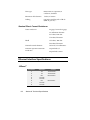
Warranty and Service
U.S. Robotics Access Corp. Limited Warranty
Your U.S. Robotics product is covered by a Limited Warranty. U.S.
Robotics warrants that the product that you have purchased from U.S.
Robotics or from a U.S. Robotics authorized reseller is free from defects
in materials or workmanship during the Limited Warranty period,
identified in the chart below, which is effective on the date of purchase.
During the Limited Warranty period, U.S. Robotics will repair or
replace the product with the same or a similar model, which may be a
remanufactured unit, at U.S. Robotics option, without charge for either
parts or labor. Replacement parts assume the remaining warranty of
the parts they replace. This Limited Warranty extends only to the
original purchaser and is non-transferable.
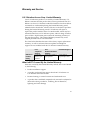
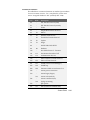
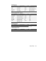
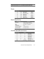
The chart below identifies the terms of the factory repair/replacement
warranty, as well as software/firmware updates and telephone
support services included with the U.S. Robotics Limited Warranty.
NETServer
Product
Family
Free
Telephone
Support
For 90 days,
effective upon
purchase
Free
Software/Firmware
Updates
For 90 days, effective
upon purchase
Hardware Support
2 years Factory
Repair/Replacement
What Is NOT Covered By the Limited Warranty
Items not covered by the Limited Warranty include, but are not limited
to, the following:
•
Product installation support
•
A product purchased from anyone other than U.S. Robotics or a
U.S. Robotics authorized reseller
•
Routine cleaning, or normal cosmetic and mechanical wear
•
A product that is modified, tampered with, misused or subjected to
abnormal working conditions, including, but not limited to,
lightning and water damage
iii
•
Damage from repair or replacement of warranteed parts by anyone
other than U.S. Robotics or a U.S. Robotics authorized service
provider
THIS LIMITED WARRANTY DOES NOT GUARANTEE YOU
UNINTERRUPTED SERVICE. REPAIR OR REPLACEMENT AS
PROVIDED UNDER THIS LIMITED WARRANTY IS THE
EXCLUSIVE REMEDY OF THE PURCHASER. THIS LIMITED
WARRANTY IS IN LIEU OF ALL OTHER WARRANTIES,
EXPRESS OR IMPLIED, INCLUDING, BUT NOT LIMITED TO,
ANY IMPLIED WARRANT OF MERCHANTABILITY OR
FITNESS FOR A PARTICULAR USE OR PURPOSE.
U.S.
ROBOTICS SHALL IN NO EVENT BE LIABLE FOR ANY
SPECIAL,
INDIRECT,
INCIDENTAL,
PUNITIVE
OR
CONSEQUENTIAL
DAMAGES
OF
ANY
KIND
OR
CHARACTER, INCLUDING, WITHOUT LIMITATION, LOSS OF
REVENUE OR PROFITS, FAILURE TO REALIZE SAVINGS OR
OTHER BENEFITS, LOSS OF DATA OR USE, DAMAGE TO
EQUIPMENT AND CLAIMS AGAINST THE PURCHASER BY
ANY THIRD PERSON, EVEN IF U.S. ROBOTICS HAS BEEN
ADVISED OF THE POSSIBILITY OF SUCH DAMAGES.
Jurisdiction Laws
This Limited Warranty gives you specific legal rights. You may have
others, which vary from jurisdiction to jurisdiction. Some jurisdictions
do not allow limitations on duration of an implied warranty, or the
exclusion or limitation of incidental or consequential damages, so the
above exclusion or limitation may not apply to you.
1997 U.S. Robotics. All rights reserved. U.S. Robotics and the U.S.
Robotics logo are registered trademarks of U.S. Robotics.
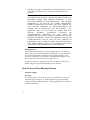
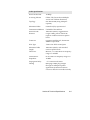
How To Access Your Warranty Services
Telephone Support
Warranty
For 90 days, effective upon product purchase, you will have access to our
technical support analysts. To obtain telephone support under the
conditions of this Limited Warranty, call the appropriate U.S. Robotics
number listed below.
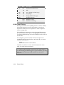
iv
Area
North America
Phone No.
1-800-231-8770
(toll free)
Monday - Friday
7. a.m. - 8 p.m.
Central Standard
Time
Weekdays
Time
Time Zone
Europe, Middle
East, Africa
353-1-205-7700
All Other
Locales
1-847-797-6600
Monday - Friday
9 a.m. - 7 p.m.
Central European
Time
Monday - Friday
7 a.m. - 8 p.m.
Central Standard
Time
What Information Should I Have Ready Before Calling For Support?
To enable U.S. Robotics to respond to your inquiry as efficiently and
effectively as possible, please have available as much of the following
general and product-specific information as possible before calling for
support.
General Information
√ Serial number & part number (both are contained within the
barcode affixed to the unit)
√ Product model name and number
√ Detailed, specific questions
Product-Specific Information
√ Applicable error messages
√ Add-on boards or hardware
√ Third-party hardware or software
√ Operating system type and revision level
Telephone Support Options
Customers who require telephone support beyond 90 days from the
purchase date will be referred to a U.S. Robotics sales representative to
establish a service contract, if desired.
Software/Firmware Updates
Warranty
For 90 days, effective upon product purchase, you will have access to U.S.
Robotics’ Systems Software/Firmware Updates from the U.S. Robotics’
Network Systems Division web site: http://totalservice.usr.com
v
Software/Firmware Update Options
Customers who require Software/Firmware updates beyond 90 days
from the purchase date will be referred to a U.S. Robotics sales
representative to establish a service contract, if desired.
Hardware Support
Warranty
During the applicable Limited Warranty period, if U.S. Robotics
determines your product requires servicing, you will be given a Service
Repair Order (SRO) number to help us track your Limited Warranty
request.
IMPORTANT: Once you have received your SRO number, mail the
product, postage prepaid and insured, to the shipping address on
page vii. Please be sure your SRO number is clearly visible on the
outside of the package and pack your unit securely.
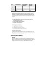
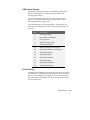
Call the appropriate U.S. Robotics number below for Hardware
Support.
Area
North America
Europe, Middle
East, Africa
All Other
Locales
Phone No.
1-800-231-8770
(toll free)
353-1-205-7700
1-847-797-6600
Weekdays
Monday - Friday
Monday - Friday
Monday - Friday
Time
7. a.m. - 8 p.m.
9 a.m. - 7 p.m.
7 a.m. - 8 p.m.
Time Zone
Central Standard
Time
Central European
Time
Central Standard
Time
Shipping Checklist - Did You Include:
√
√
√
√
√
√
vi
Your Name
Your Company’s Name
Return Shipping Address
A Contact Telephone Number
Serial & Part Numbers (contained in barcode attached to the unit)
Brief Problem Description
Shipping Address
North America and Locations Outside
Europe, Middle East & Africa
U.S. Robotics
ATTN: SRO Receiving
1800 W. Central Rd.
Mt. Prospect, IL 60056-2293
SRO#......................................
Europe, Middle East, Africa
U.S. Robotics Services, Ltd
ATTN: RMA Department
5 Richview Office Park
Clonskeagh, Dublin 14
Ireland
Hardware Support Options
Customers who require out-of-warranty hardware support will be
referred to a U.S. Robotics sales representative to establish a service
contract, if desired.
Technical Support
For technical assistance, contact the U.S. Robotics Systems Product
Support Department in one of the following ways. Whichever way you
contact us, please have the product serial number(s) available.
Mail
Telephone
America Online
CompuServe
Anonymous FTP
World Wide Web
N. America:
1800 W. Central Rd., Mt. Prospect, IL
Europe, Middle East, Africa:
5 Richview Office Park
Clonskeagh, Dublin 14, Ireland
From U.S. or Canada: (800) 231-8770 (toll-free)
From Mexico, S. America or Asia:
(Your international carrier code) 847 797-6600
From Ireland: 1.205.7700
From Europe (outside Ireland, Middle East, Africa):
(Your international carrier code) 353.1.205.7700
Keyword USROBOTICS
GO USROBOTICS
ftp.usr.com* Username=Anonymous
Password=your internet address.
http://totalservice.usr.com
*The FTP is for downloading files only.
Rev. 2/98
vii
viii
Table of Contents
Overview
1-1
What’s New with NETServer 8/16 Plus ...................................... 1-1
AppleTalk Phase II Support ............................................................ 1-2
Enhanced SNMP Management Support.......................................... 1-3
RIP Version 2 and Classless Routing (CIDR) Support ................... 1-4
RTMP Support ................................................................................ 1-4
IPX and AppleTalk Spoofing.......................................................... 1-4
IPXWAN Support ........................................................................... 1-5
IPX Dialout and Address Pools....................................................... 1-5
TFTP Download Capability ............................................................ 1-5
Enhanced Event Logging and Accounting ...................................... 1-5
Command File Support ................................................................... 1-5
Enhanced Link-Layer Compression Support................................... 1-6
Enhanced RADIUS Support............................................................ 1-6
Improved Security........................................................................... 1-6
Command Line Editing ................................................................... 1-7
NETServer 8/16 Plus Overview................................................... 1-7
IP Terminal Service ........................................................................ 1-7
Network Dial In Access .................................................................. 1-9
Dial-Out Access ............................................................................ 1-10
LAN-to-LAN Routing ................................................................... 1-11
Basic Installation and Setup
2-1
What’s in the Package.................................................................. 2-1
Checklist ...................................................................................... 2-1
System Administrator Requirements ........................................... 2-2
I-modem Basics............................................................................ 2-3
ISDN Basic Rate Interface .............................................................. 2-4
Inside the NETServer Plus I-modem............................................... 2-5
Ordering ISDN Service................................................................ 2-6
The U.S. Robotics I-team................................................................ 2-7
Requesting Service.......................................................................... 2-7
Table of Contents
ix
Accessing the Configuration Interface ........................................ 2-9
Establishing Communications with NETServer Plus.......................2-9
Automated Quick Setup Programs.................................................2-10
Advanced Management Capabilities..............................................2-10
Command Line Interface Conventions...................................... 2-11
Hardware Installation ................................................................ 2-15
Installing on the Desktop ...............................................................2-16
Installing on the Rack ....................................................................2-16
Cabling ..........................................................................................2-18
Setup to Talk to the NETServer 8/16 Plus.....................................2-19
Using the CLI Quick Setup Program ......................................... 2-20
Setting Up the I-modems ........................................................... 2-28
Setting Up the System Manually ............................................... 2-29
Manually Configuring the LAN Interface ................................. 2-31
IP Configuration ............................................................................2-32
IPX Configuration .........................................................................2-35
AppleTalk Configuration...............................................................2-38
Configuring a Manage User ...................................................... 2-39
Manually Configuring the WAN Interface................................ 2-40
Configuration Overview
3-1
Setting Up NETServer 8/16 Plus Applications ........................... 3-1
Configuration Command Overview ............................................ 3-2
Configurable Table Overview ..................................................... 3-3
Interface Table.................................................................................3-3
User Table .......................................................................................3-3
Facilities Table ................................................................................3-4
Hosts Table......................................................................................3-4
Initialization Script Configuration Table .........................................3-4
Module Table...................................................................................3-4
Network Table .................................................................................3-5
Filter and Associated Tables............................................................3-5
Routes Table....................................................................................3-5
SNMP Configuration Tables ...........................................................3-5
Syslog Table ....................................................................................3-6
Table of Contents
x
IP Terminal Server Setup
4-1
Configuring the Remote Computer.............................................. 4-2
Configuring Login Hosts ............................................................. 4-3
Configuring Login Users ............................................................. 4-5
IP Terminal Service Case Study .................................................. 4-9
Network Dial In Access
5-1
Overview...................................................................................... 5-3
IP Parameters .................................................................................. 5-3
IPX Parameters ............................................................................... 5-4
AppleTalk Parameters..................................................................... 5-4
Remote Computer Setup .............................................................. 5-5
Configuring Address Pools.......................................................... 5-6
Configuring an IP Address Pool...................................................... 5-6
Configuring an IPX Address Pool................................................... 5-6
Configuring an ARAP AppleTalk Address Pool............................. 5-7
User Configuration Overview...................................................... 5-7
NETServer Defaults ........................................................................ 5-8
Remote Addressing Options............................................................ 5-8
Network User Types ....................................................................... 5-8
Configuring an IP User ................................................................ 5-9
Configuring an IPX User ........................................................... 5-12
Configuring an AppleTalk User ................................................ 5-15
Configuring PPP Parameters...................................................... 5-17
Configuring Additional Parameters ........................................... 5-18
Remote Access Case Study........................................................ 5-19
Assumptions.................................................................................. 5-19
Configuring User_A...................................................................... 5-20
Configuring User_B ...................................................................... 5-20
Configuring User_C ...................................................................... 5-21
Table of Contents
xi
Network Dial-Out Access
6-1
Overview ..................................................................................... 6-2
IP/IPX Dial-Out...............................................................................6-2
Telnet Dial-Out................................................................................6-3
Network Dial-Out Configuration Overview................................ 6-3
Network Dial-Out Configuration................................................. 6-4
Add Modem Groups ........................................................................6-4
Add Dial-Out Service ......................................................................6-4
Add Dial-Out Users .........................................................................6-5
Set Global Dial-Out Parameters.......................................................6-5
Telnet users......................................................................................6-6
PC Client Software Installation and Setup .................................. 6-8
NPC Client Installation for DOS .....................................................6-8
NPC Client Installation for Windows 3.x ......................................6-12
NPC Client Installation for Windows 95 .......................................6-15
Opening an Application............................................................. 6-18
An Overview of NPC’s Windows-Based Options .........................6-20
LAN-to-LAN Routing
7-1
LAN-to-LAN Routing Overview................................................. 7-2
Connection Establishment ...............................................................7-2
Dynamic Routing Settings ...............................................................7-3
Dialout Scripts .................................................................................7-3
Bandwidth-On-Demand ...................................................................7-3
IP Routing........................................................................................7-3
IPX Routing.....................................................................................7-4
AppleTalk Routing ..........................................................................7-4
Static Routes ....................................................................................7-5
Dynamic Routes...............................................................................7-5
How Packets are Routed ..................................................................7-6
Establishing Connections to Remote Gateways ...............................7-6
Authentication ............................................................................. 7-7
PAP Authentication .........................................................................7-7
CHAP Authentication ......................................................................7-7
Configuring LAN-to-LAN Routing............................................. 7-8
LAN-to-LAN Routing Case Study ............................................ 7-18
Assumptions ..................................................................................7-19
Configuring NETServer A.............................................................7-19
Table of Contents
xii
Configuring NETServer B ............................................................ 7-23
Packet Filters
8-1
Filtering Overview ....................................................................... 8-2
NETServer Filtering Capabilities.................................................... 8-2
NETServer Filtering Applications................................................... 8-3
Information Sources ........................................................................ 8-3
Filter Types .................................................................................. 8-4
Data Filters...................................................................................... 8-4
Advertisement Filters ...................................................................... 8-5
Generic Filters................................................................................. 8-6
Creating Filters ............................................................................ 8-6
Filter File Components.................................................................... 8-6
Creating Filter Files....................................................................... 8-11
Configuring Filters..................................................................... 8-14
Interface Filters ............................................................................. 8-14
User Filters.................................................................................... 8-15
Assigning Filters ........................................................................... 8-15
Managing Filters ........................................................................ 8-17
Filter Examples .......................................................................... 8-20
IP Packet Filter Rule Examples..................................................... 8-20
IPX Packet Filter Rule Examples.................................................. 8-26
AppleTalk Packet Filter Rule Examples ....................................... 8-28
Keywords ................................................................................... 8-30
Administrative Tools
9-1
Reconfiguring Your System ........................................................ 9-1
Customizing CLI Parameters .......................................................... 9-1
Customizing NETServer Plus Parameters....................................... 9-3
Communicating with Remote and Local Sites............................. 9-6
Dial and Connect Commands.......................................................... 9-6
Exiting the CLI................................................................................ 9-7
Network Services ............................................................................ 9-7
Troubleshooting Commands...................................................... 9-12
Viewing Facility Errors ................................................................. 9-12
Terminating an Active Process...................................................... 9-12
Resolving Addresses ..................................................................... 9-13
Resolving Host Names .................................................................. 9-13
Table of Contents
xiii
Using Ping .....................................................................................9-13
Using Echo ....................................................................................9-14
Viewing Interface Status, Settings .................................................9-14
Viewing Netserver Plus System Information .................................9-15
Displaying System Information................................................. 9-15
List Commands ..............................................................................9-15
Show Commands ...........................................................................9-16
Performing a Software Download ............................................. 9-18
DIP Switches .................................................................................9-18
Installation .....................................................................................9-22
Notices & Technical Specifications
A-1
Notices: United States .................................................................A-1
FCC Part 15 Compliance Statement ...............................................A-1
For More Information .....................................................................A-2
Analog V.34 Model: FCC Part 68 Compliance Statement .............A-2
BRI U Model: FCC Part 68 Compliance Statement .......................A-3
BRI S/T Model: FCC Part 68 Compliance Statement ....................A-3
Notices: IC (Industry Canada).....................................................A-4
Analog V.34 Model ........................................................................A-4
BRI S/T Model ...............................................................................A-4
BRI U Model ..................................................................................A-4
Canadian Installations.....................................................................A-5
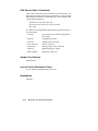
Hardware Specifications..............................................................A-5
Environmental Specifications......................................................A-6
Power Specifications ...................................................................A-6
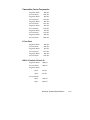
External Serial Port (Console) Specifications.............................A-7
Ethernet Interface Specifications.................................................A-8
Modem Interface Specifications................................................A-11
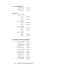
System Standards and Specifications ........................................A-12
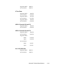
Software Specifications.............................................................A-21
Addressing Schemes
B-1
IPX Addressing Basics ................................................................B-1
IP Addressing Basics ...................................................................B-2
Subnetting....................................................................................... B-3
Supernetting (Advanced TCP/IP)................................................B-6
Table of Contents
xiv
Supernet Example .........................................................................B-10
Supernetting and the NETServer...................................................B-11
IP Subnet Mask Address Table................................................. B-12
LEDs and DIP Switches
C-1
LED Overview ............................................................................ C-1
Run/Fail LED.............................................................................. C-2
Modem Indicators ....................................................................... C-3
NETServer Indicators ................................................................. C-4
Flash ROM LED .............................................................................C-4
LAN TX LED .................................................................................C-4
LAN RX LED .................................................................................C-4
LAN STATUS LED........................................................................C-5
MGT LED.......................................................................................C-5
DIP Switches............................................................................... C-5
V.34 DIP Switches ..........................................................................C-6
I-modem DIP Switches ...................................................................C-8
NETServer CONFIGURATION DIP Switches ..............................C-9
Event Messages
D-1
Event Logging............................................................................. D-1
Syslog Host Event Logging............................................................ D-1
Console Event Logging .................................................................. D-2
Local Flash File Event Logging ..................................................... D-2
Event Logging Levels ................................................................. D-2
Using Syslog ............................................................................... D-3
Configuring Syslog Hosts on the NETServer................................. D-3
Setting the Event Log Level ........................................................... D-4
Event Message Examples ........................................................... D-5
IP Messages ................................................................................... D-5
IPX Messages................................................................................. D-8
Call Initiation Process Messages.................................................... D-9
User Manager Messages............................................................... D-10
Filter Manager Process Messages ................................................ D-10
UDP Messages ............................................................................. D-11
Configuration File Manager Messages......................................... D-11
Telnet Messages........................................................................... D-12
IPX/IP Dial-out Process Messages............................................... D-13
Table of Contents
xv
RADIUS Authentication and Accounting
E-1
RADIUS Overview...................................................................... E-1
RADIUS Authentication................................................................. E-1
RADIUS Accounting ...................................................................... E-2
Obtaining RADIUS......................................................................... E-2
Performing Authentication .......................................................... E-2
RADIUS Authentication Process.................................................... E-3
RADIUS Security Server User Table Entries ............................. E-4
Required Parameters....................................................................... E-4
Optional Parameters........................................................................ E-6
NETServer-Specific Parameters ................................................... E-16
CHAP Authentication Using RADIUS ......................................... E-21
Configuring RADIUS from the CLI.......................................... E-22
Configuring RADIUS Authentication Settings ............................. E-22
Enabling and Disabling Authentication ........................................ E-23
Configuring RADIUS Accounting Settings .............................. E-24
Configuring RADIUS Accounting Settings .................................. E-24
Enabling and Disabling RADIUS Accounting.............................. E-25
RADIUS Accounting Examples ................................................... E-26
Index
1
Table of Contents
xvi
Chapter 1
Overview
While the NETServer 8/16 Plus release nominally marks the
latest upgrade in the NETServer V.34/I-modem family, it truly
represents a new phase in product development by the
introduction of a brand new code set. This development is a
considerable departure from 3.x releases in how the NETServer
command set works, with enhanced features and greater ease of
use.
Generally speaking, the Command Line Interface (CLI) is more
versatile than earlier command sets, offering a path to more
inclusive management and detailed accounting, a fast and easy
configuration wizard and links to an intuitive GUI configurator
- the NETServer Manager Plus (NMP).
What’s New with NETServer 8/16 Plus
With a few exceptions, the NETServer 8/16 Plus encompasses
all the functionality of the NETServer 3.x, and more. NETServer
8/16 Plus adds the following new features:
• AppleTalk Phase II support
• Enhanced (full) SNMP management support
• RIP version 2 and classless routing (CIDR) support
• ARAP dial-in and RTMP support
• IPX and AppleTalk spoofing
• IPXWAN support
• IPX dial-out and address pool capability
• TFTP download capability
• Enhanced event logging and accounting
• Command file support
Overview
1-1
• Enhanced link-layer compression support
• Enhanced RADIUS support
• Improved security
• Command line editing
Each new feature is described generally in the sections below.
AppleTalk Phase II Support
Full support for AppleTalk Phase II is new in NETServer 8/16
Plus. The following protocols are supported:
1-2
•
DDP - Datagram Delivery Protocol is a network-layer
protocol that encapsulates and forwards transport layer
packets on LANs and WANs
•
RTMP - Routing Table Maintenance Protocol establishes and
maintains routing tables for forwarding packets
•
AEP - AppleTalk Echo Protocol allows a node to send a
packet to any other node and to receive an echoed copy of
that packet in return. It is similar to IP’s PING
•
NBP - Name Binding Protocol is a transport-level protocol
that converts entity names to addresses, learning which
networks belong to a zone
•
ZIP - Zone Information Protocol finds and maps network
numbers to zone names
•
AARP - AppleTalk Address Resolution Protocol reconciles
addressing discrepancies in networks that support more
than one set of protocols
•
ARAP - AppleTalk Remote Access Protocol defines login
and authentication as well as the AppleTalk data format
•
AT-PPP - AppleTalk Point to Point Protocol sets up a WAN
between two AppleTalk networks
Overview
Enhanced SNMP Management Support
NETServer 8/16 Plus includes full Windows-based SNMP
version 1 management support that allows you to:
•
Configure the NETServer
•
Perform accounting functions
•
Generate SNMP traps.
The following MIB types are supported:
•
Standard MIB I and II
•
OSPF MIB
•
IPX MIB
•
AppleTalk MIB
•
Ethernet MIB
•
USRobotics proprietary MIBs
Five common SNMP traps are supported by the NETServer:
•
Cold starts
•
Warm starts
•
Link up
•
Link down
•
Authentication failure
Overview
1-3
RIP Version 2 and Classless Routing (CIDR) Support
NETServer 8/16 Plus implements RIPv2, an extension of the
original RIP protocol. RIPv2 adds the following capabilities to
the original RIP protocol:
•
Subnet masks
•
Specification of next hop
•
Authentication
•
Multicast support
Classless Inter-Domain Routing (CIDR) is a method for reducing
the burden on routing tables in the Internet. CIDR provides a
subnetwork for Internet service providers by combining a
number of Class C addresses into one. The RIPv2 subnet mask
extension allows RIPv2 to be used in CIDR-compliant networks.
RTMP Support
NETServer 8/16 Plus supports the Routing Table Maintenance
Protocol (RTMP) which is used to maintain routing tables that
are central to the process of forwarding datagrams from any
source socket to any destination socket on the Internet.
IPX and AppleTalk Spoofing
Spoofing is a cost-saving way to make two sides of a
disconnected circuit believe that the connection still exists in
order to limit network traffic and preserve the advantages of on
demand service. In addition to providing IP spoofing
capabilities (RIPv1 and RIPv2) included in previous NETServer
versions, NETServer 8/16 Plus supports IPX and AppleTalk
spoofing between NETServers.
Spoofing protocols include:
1-4
•
IPX RIP
•
IPX Watchdog
•
IPX Serialization
•
SPX Keepalives
•
AppleTalk RTMP
Overview
IPXWAN Support
NETServer 8/16 Plus supports the IPXWAN protocol used by
Novell to negotiate the WAN network number and the
transmission delay over the link.
IPX Dialout and Address Pools
NETServer 8/16 Plus now supports dialout over IPX and the
creation of address pools to conserve IP address usage.
TFTP Download Capability
You can use the Trivial File Transfer Protocol (TFTP) to
download files to the NETServer Plus flash memory.
Enhanced Event Logging and Accounting
NETServer 8/16 Plus supports these new features:
• Critical event logging to flash memory
• Event logging to a UNIX or Total Control accounting
server
• Event logging to multiple syslog hosts
• ICMP error message logging to a syslog server
• Accounting information logging to a RADIUS accounting
server
• ANI and DNIS call information logging
Command File Support
NETServer 8/16 Plus lets you create a command file (similar to
a *.BAT file) to spawn any number of CLI commands or
processes. You can perform several configuration, maintenance,
or diagnostics commands from the console. Simply add the CLI
commands using your favorite editor, TFTP the file to the
NETServer's flash memory, and run the do command.
Overview
1-5
Enhanced Link-Layer Compression Support
NETServer 8/16 Plus supports these link-layer compression
methods:
•
STAC LZS - a compression mode that uses the LZS-based
algorithm ( the most common PPP algorithm)
•
Microsoft PPC - a compression mode that differs slightly
from STAC, utilized by Windows 95 and NT
•
Ascend - a compression mode based on STAC LZS with
differences in the way initial sessions and dictionary resets
are negotiated
Enhanced RADIUS Support
NETServer 8/16 Plus has the following RADIUS-related
features:
•
RADIUS Challenge support - second level authentication
•
Settable RADIUS retransmission parameters - the number
of retransmissions and time-out can be specified on the
primary RADIUS server
•
Mirroring - accounting information is sent to primary and
secondary servers
Improved Security
NETServer 8/16 Plus supports a wide array of packet filters that
can accept or reject packets based on rules that you specify. You
can configure the NETServer to filter packets entering and
exiting NETServer ports using input and output filters. In
addition, you can apply these filters to a specific user. You can
also use call filters to allow or prohibit call initiation.
Filter types include:
Data filters - Perform filtering based on protocol-specific
information for IP, IPX and AppleTalk packets
Advertisement filters - Performs filtering based on information
contained in advertisement packets such as IP-RIP, IPX-RIP,
IPX-SAP, AppleTalk RTMP, and AppleTalk ZIP protocols
1-6
Overview
Generic filters - Protocol-independent filters can be used to
filter packets based on their byte and offset values
Command Line Editing
The NETServer 8/16 Plus supports complete editing from
command line including character, word and line deletion.
NETServer 8/16 Plus Overview
The NETServer 8/16 Plus is a multi-protocol, dial-up router and
terminal server commonly described as a remote access server.
The NETServer Plus can perform four basic applications:
•
IP Terminal Service
•
Network Dial-in Access
•
LAN-to-LAN Routing
•
Dial-Out Access
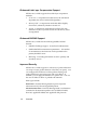
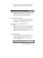
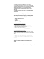
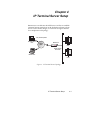
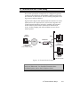
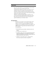
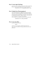
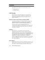
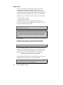
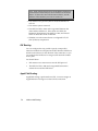
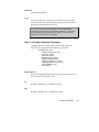
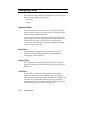
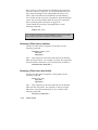
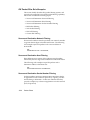
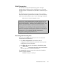
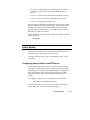
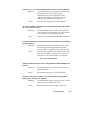
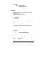
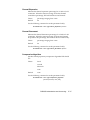
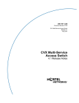
IP Terminal Service
NETServer 8/16 Plus provides network access for dumb
terminals or computers that emulate dumb terminals. The
ASCII data stream to and from these remote terminals is
converted into a networking protocol (Telnet, Rlogin, or
ClearTCP) and a session is established with a host to provide an
IP terminal service connection on NETServer’s local network.
The NETServer offers extensive access security, dialback, and
substantial configurability for terminal service connections. See
Figure 1 on the next page.
Overview
1-7
TTY (Terminal) Data
Remote Office
User
PSTN/
ISDN
NETServer
Host
Telnet, Rlogin
ClearTCP
Mobile User
Host
Figure 1. IP Terminal Service Topology
1-8
Overview
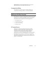
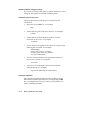
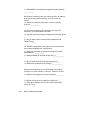
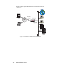
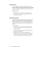
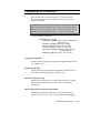
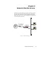
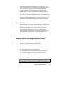
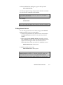
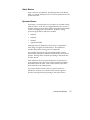
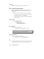
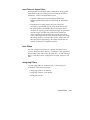
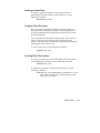
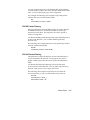
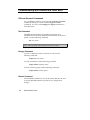
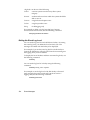
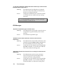
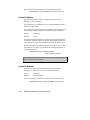
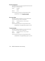
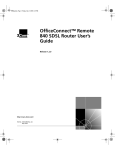
Network Dial In Access
NETServer 8/16 Plus provides dial-in network access for remote
users. Remote IP, IPX, or AppleTalk networked users can dial
in and attach to the local network as if they were local nodes.
Packets transmitted over the dial-in connection are encapsulated
using the following protocols:
•
PPP (Point-to-Point Protocol)
•
SLIP (Serial Line IP Protocol)
•
ARAP (AppleTalk Remote Access Protocol).
NETServer Plus offers access security, dialback, and substantial
configurability for dial-in network connections. See Figure 2
below.
Internet
Remote Office
User
PPP, SLIP,
or ARAP
PSTN/
ISDN
NETServer
PCs
IP, IPX, and
AppleTalk
Mobile User
File
Server
RADIUS
Server
Figure 2. Network Dial In Topology
Overview
1-9
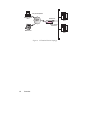
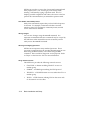
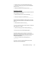
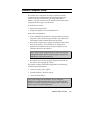
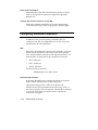
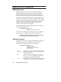
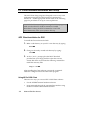
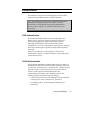
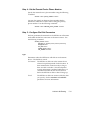
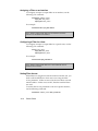
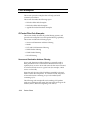
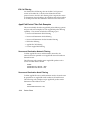
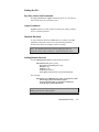
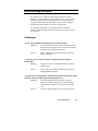
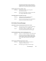
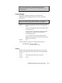
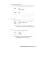
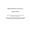
Dial-Out Access
NETServer 8/16 Plus modem ports can be accessed by network
PCs and workstations to provide users with dialout services.
This allows network users to send faxes, connect to Bulletin
Board Systems (BBS), information services such as CompuServe,
or the Internet over a dial-up PPP connection. LAN users
require an NCSI-compatible communications application to
access NETServer Plus modems (see Chapter 6: Network DialOut Access for more information). See Figure 3 below.
PSTN/
ISDN
Dial-Out Modem
Connection
NETServer
IP, IPX,
Telnet
Figure 3. Dial-Out Topology
1-10
Overview
PCs
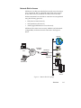
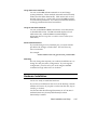
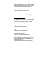
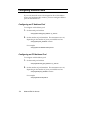
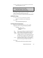
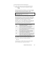
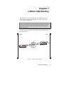
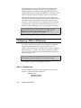
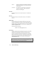
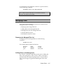
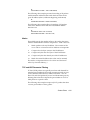
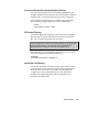
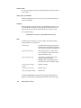
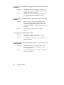
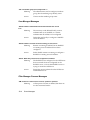
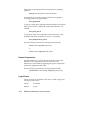
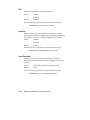
LAN-to-LAN Routing
NETServer 8/16 Plus performs dial-up routing between
facilities. This occurs when one NETServer dials up another and
logs in as a user, creating a NETServer - NETServer rather than
a user - NETServer connection. See Figure 4 below.
Connections can be set up in a number of ways: manual, ondemand, timed, and continuous. You can configure connections
to use various routing and protocol parameters. The NETServer
8/16 Plus is also capable of establishing additional connections
to increase bandwidth automatically when traffic increases.
LAN A
LAN B
PSTN/
ISDN
NETServer B
NETServer A
Figure 4. LAN-to-LAN Routing Topology
Overview
1-11
1-12
Overview
Chapter 2
Basic Installation and Setup
This chapter describes what to do now that you are acquainted
with NETServer 8/16 Plus functionality. Read the following
sections appropriate to your unit and skip the rest.
What’s in the Package
The following checklist itemizes what you need before you can
use NETServer 8/16 Plus. At installation, it is assumed the
checklist was completed, so, check off the items now. It will
make your installation and set up process easier and quicker.
❑ Inspect the contents of the NETServer 8/16 Plus package.
❑ Obtain an Ethernet connection on your LAN.
❑ Obtain a terminal emulator over the serial port on your PC.
Checklist
❑ NETServer 8/16 Plus V.34 or I-modem (8 or 16-port unit)
❑ Console cable (RJ45 - RS232)
❑ 4/8 I-modem cables (RJ45 - RJ45) - I-modem unit only
❑ Null modem adapter
❑ Power cord
❑ Mounting brackets, screws and rubber feet
❑ Getting Started with NETServer 8/16 Plus card
❑ NETServer 8/16 Plus User Manual
Basic Installation and Setup
2-1
❑ NETServer 8/16 Plus CLI Reference Guide
❑ NETServer Manager Plus diskette
❑ NETServer 8/16 Plus AT Modem Reference Guide
❑ Customer Support & Warranty/Registration cards
❑ PC Software Download (PCSDL) diskettes (2)
❑ Release Notes (readme.txt file)
❑ Stampede 4.0 Remote Office CD-ROM
❑ NCSI Client Diskettes (3)
System Administrator Requirements
This document assumes that you are familiar with Novell, IP
and/or AppleTalk networks. Novell offers a variety of
programs to certify administrators in network technology.
TCP/IP and AppleTalk information is also available from a
variety of sources, some of which are covered below.
If you require the assistance of a qualified professional, consult
your nearest authorized U.S. Robotics Platinum reseller for
advice. For a service fee, U.S. Robotics also offers qualified
engineering assistance on site. Contact Net/Sys Product
Support at (800) 231-8770 for more information.
TCP/IP Reference Material
The network manager is typically responsible for devising an
addressing strategy appropriate for the size and growth
potential of the network. We recommend the following
reference material for TCP/IP:
Comer, D.E., Internetworking with TCP/IP Volume I:
Principles, Protocols and Architecture, Prentice-Hall,
Englewood Cliffs, New Jersey, 1995.
You must obtain registered addresses from the Internet’s
Network Information Center (InterNIC) for IP machines and
networks that will be attached to the Internet. InterNIC can be
contacted at the following address and phone number.
2-2
Basic Installation and Setup
Network Solutions
InterNIC Registration Services
505 Huntmar Park Drive
Herndon, VA 22070
1-703-742-4777
For networks with only a few IP machines, you may be able to
contact your local Internet access provider and let them handle
the details.
AppleTalk Reference Material
For guidance on AppleTalk network administration, we
recommend the Apple Communications Library's Apple
Communications Technical series. You should specifically
consult the following document
Sidhu, Andrews and Oppenheimer, Inside AppleTalk,
Addison-Wesley Publishing Company, Inc., Reading,
Mass., 1989
I-modem Basics
An Integrated Services Digital Network (ISDN), is an end-toend telecommunications network that supports a wide range of
services including voice and data. ISDN technology is used in
both private and public networks across the world.
ISDN is designed to integrate the transmissions from a variety
of devices such as computers, telephones, and fax machines into
a single digital network.. The advantages of using digital
technology over analogue transmission methods are that digital
transmissions are more accurate, which improves the reliability
of calls. That accuracy, allows for transmission rates of up to 64
kbps per channel. ISDN also has greater bandwidth, fewer
errors during transmissions, and increased speed in setting up
and tearing down calls.
NETServer Plus I-modems communicate over ISDN Basic Rate
Interface (BRI) lines. You need to order the channels from your
ISDN service provider before you can use your NETServer’s
I-modems.
Basic Installation and Setup
2-3
BRI works over the same wiring that is in place for analog
telephone lines. The difference is in the equipment you attach
and signaling used.
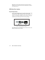
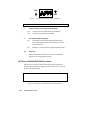
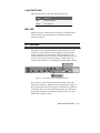
ISDN Basic Rate Interface
Physical Appearance
At your site, the ISDN lines will use RJ45 wall jacks and cables,
each of which, in ISDN, make up the S/T interface. RJ45
connectors have 8 pins. See Figure 1 below. The connectors, or
cables, for attaching the NETServer Plus modems to the jacks
installed by your service provider are in the package.
Figure 1. RJ45 Connector and Jack
Your ISDN service provider adds a line card at its end of each
BRI that adapts the line for ISDN.
2-4
Basic Installation and Setup
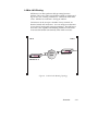
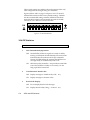
B- and D-channels
BRI typically contains three channels. These channels are
created using complex signaling techniques.
Usually BRI is made up of two 64 kbps B (bearer) -channels and
one 16 kbps D (delta) -channel. The B-channels carry data or
voice traffic. The D-channel is used for call control: the setting
up and tearing down of calls. See Figure 2 below.
Figure 2.
ISDN BRI—Three Channels over One Pair of Wires
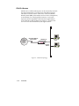
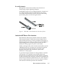
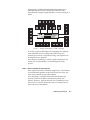
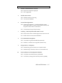
Inside the NETServer Plus I-modem
Each NETServer Plus 8-port I-modem contains four separate
ISDN terminal adapters. While these terminal adapters don’t
really look like the stack of Courier I-modems in the figure on
the next page, they do operate as if they were Courier desktop Imodems plugged into a computing device (in this case, the
NETServer routing engine) via a pair of serial cables.
Unlike an analog modem, each I-modem must be able to process
a BRI ISDN phone line, containing two separate data channels.
An I-modem maps these B-channels to its internal serial
interfaces which are in turn connected to ports on the
NETServer’s routing engine.
To provide the unique emulation of analog modems, I-modems
will respond to AT commands received from either serial
interface. Keep in mind that each pair of B-channels/serial lines
is really serviced by only one device. Certain AT commands will
affect both serial interfaces simultaneously. See a later chapter in
this User Manual and the NETServer 8/16 Plus Reference Guide for
more details on I-Modem operation and commands.
Basic Installation and Setup
2-5
The NETServer routing engine is a completely separate device
from any of the I-modems. Its job is to route data from its ports (all
B-channels of all internal I-modems) to its LAN (Ethernet)
interface and vice versa. However, it is also able to configure and
use the internal I-modems to establish connections with remote
devices. See Figure 3 below.
Figure 3. Conceptual view of the NETServer/8 I-modem
Ordering ISDN Service
Although efforts are being made to simplify ISDN ordering, it
can still be a complex process. This section should give you and
your local telephone company all the information you need to
set up your ISDN lines correctly. Here’s what to do:
1
Call your local telephone company to request your ISDN
lines. Explain NETServer 8/16 Plus requirements as
described in this section.
2
Your local telephone company will give you information
about your lines and settings.
3
Program the line’s settings into your NETServer’s internal Imodems.
If, after looking over this chapter, you decide you would
like assistance with the ordering process, call the U. S.
Robotics I-Team at (800) 550-7800.
2-6
Basic Installation and Setup
The U.S. Robotics I-team
The I-team is a group within USR’s Customer Support
department that provides ISDN ordering and configuring
assistance. The I-team helps you determine availability and
pricing of ISDN service in your location, installation costs.
They also determine lead time for installation and will help
coordinate the configuration of the telephone company’s
equipment, so your NETServer Plus I-modem will work
properly. You can get information about the I-team, as well as
local telephone company contacts and pricing, from:
●
The I-team on the World Wide Web: http://www.usr.com
●
U.S. Robotics Fax on Demand at (800) 762-6163
●
The U.S. Robotics I-team at (888) USR-ISDN
You may also access the NETServer 8/16 I-modem Website at:
http://www. insideline.usr.com/function/isdn/index.html#netserver
Requesting Service
Call the ISDN department of your local telephone company. and
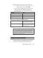
request the following configuration for each BRI line.
1
Request 4 BRI ISDN lines for a NETServer Plus I-modem 8port (8 lines for 16-port version). Each should be configured
with Bellcore Capability Package S (listed in Bellcore SR3840). If your phone company doesn’t recognize Bellcore
capability packages, you can also ask for a service package
called Intel Blue, which has characteristics similar to
Bellcore S. If your telco recognizes neither of these service
packages, request the following specific ISDN services and
service characteristics for each line:
• 2 B channels, with no packet mode data on B or D
channel
• Circuit-switched voice and data (CSV/D) call type
support for each channel
• 2 telephone Directory Numbers (Dns) and 2 Service
Profile Identifiers (SPIDs)
• Multipoint bus configuration
Basic Installation and Setup
2-7
• Dynamic TEI assignment
• RJ45 connector preferred (RJ11 is acceptable)
2
Specify your preferred long distance provider.
3
Ask the type of central office switch at which your ISDN
line will terminate, and which protocol controls your calls.
❑ If your switch is AT&T 5ESS, running National ISDN-1
or Custom, request Terminal Type A.
❑ If your switch is AT&T 5ESS Custom, note that:
The NETServer 8/16 Plus’ internal I-modems currently
support only one SPID and one DN per channel when the
central office switch runs the AT&T 5ESS Custom protocol.
The use of one SPID and one DN per channel prevents two
analog-based calls from going over the same channel at the
same time. Analog-based calls include connections to
remote modems or fax machines.
We strongly recommend that you request National ISDN-1
as your switch protocol on the AT&T 5ESS switch, if
possible. If you can’t get National ISDN-1, be sure to
request two SPIDs and two DNs from your telephone
company, for future flexibility.
❑ Northern Telecom DMS-100 switch running NT’s
“Custom” protocol
4
Make sure your local telephone company gives you the
following information.
• DN numbers. If the line is provisioned for voice and
data there may be a separate number for the voicecarrying B channel.
• SPID numbers. Not all telephone companies use SPIDs
(European customers may disregard), but if so, there’ll
be one for each B-channel.
• Central office switch type and protocol
• If the switch does not auto-assign TEIs (all but the AT&T
5ESS do), then you need one fixed TEI per B-channel.
2-8
Basic Installation and Setup
Accessing the Configuration Interface
This section explains how to attach to the configuration interface
locally via the console port or remotely via the NETServer
Manager Plus.
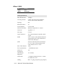
Establishing Communications with NETServer Plus
Depending on your type of computer (options shown below),
configure the terminal emulation communications settings to:
•
9600 baud
•
8 data bits
•
no parity
•
1 stop bit
•
direct connect
IBM-PC Compatible Computers
Windows Terminal (included with Microsoft Windows) and
Procomm Plus are popular communications packages which
support VT100 terminal emulation for IBM-PC compatible
computers. HyperTerminal, bundled with Windows 95, also
supports terminal emulation.
Macintosh Computers
Procomm, MicroPhone, White Knight, Kermit, Red Ryder,
VersaTerm and ZTerm (a shareware application available on the
Internet and many on-line services) are popular
communications programs which carry VT100 terminal
emulation service for Macintosh computers. If you don’t have a
communications package or your program doesn’t support
VT100 emulation, Zterm will function just as well.
UNIX-Based Computers
Kermit, minicom and tip are typical terminal emulation
programs for UNIX-based computers. Depending on the
Basic Installation and Setup
2-9
platform you’re using, you may need to modify a configuration
file for VT100 settings.
Automated Quick Setup Programs
As an alternative to the manual configuration described in this
manual, NETServer Plus offers two easy, automated
configuration programs (described below) to quickly and
efficiently get your unit up and running.
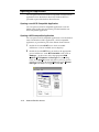
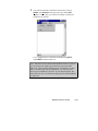
NETServer Manager Plus Setup Wizard
A Setup Wizard is built into our Windows-based NETServer
Manager Plus (NMP) which can be accessed remotely (without
hooking up the console port) and doesn’t require using the
Command Line Interface (CLI). We recommend this program
for its graphical user interface and means of configuring your
unit via SNMP. See the AM pamphlet for easy setup.
Quick Setup (CLI)
NETServer 8/16 Plus' automated Quick Setup program provides
user-friendly configuration on the CLI. It performs simple setup
for your entire system or for individual sections. Simply answer
the mostly yes or no queries and the program does the rest. It is
accessed automatically upon installing your hardware and
turning on the NETServer. If you prefer, you have the option to
start configuration in Quick Setup and continue in the AM.
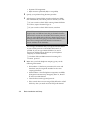
Note: The Quick Setup (CLI) program is designed only for initial
setup of the NETServer. When setup is complete, this one-time
program will alter your configuration files, which the program
cannot edit. If you make an error and need to restart, use the
delete configuration command to reboot and return to factoryconfigured defaults.
Advanced Management Capabilities
You may also download upgraded code to your NETServer
using the PCSDL program. See the Performing a Software
Download section in Chapter 9: Administrative Tools for more
2-10
Basic Installation and Setup
information. Filtering, using the Trivial File Transfer Protocol
(TFTP), and spoofing, are two other management tools provided.
Spoofing is supported when two NETServers are connected
only.
Command Line Interface Conventions
The NETServer Plus’ Command Line Interface (CLI) is an
interactive application that allows you to view information and
set system parameters. This section provides general
information about CLI command conventions and usage.
Most commands are not case sensitive
You can type most commands and parameters in upper or lower
case except for <name> and [password] values which require
typing the correct case. AppleTalk zones specified in the wrong
case will also return an incorrect value.
Many commands are position independent, multi-tiered
and use keywords
Multi-tiered commands let you type the base command (e.g.: set
interface) and implement many more parameters (host_type,
host_address, etc). Position independence does not require all
parameters to be specified at once, nor in sequence, to work. But
typing a keyword in the base command such as network in set ip
network is mandatory to enable the command.
You can abbreviate commands
You can abbreviate most commands and command options with
the first few letters that distinguish that command from any
other. For example, while the full command to list TCP
connections is list tcp connections, you need only type list tcp c
to invoke the command.
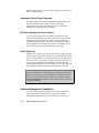
Note: The CLI will display an error message if you enter an
abbreviated command that is ambiguous.
Basic Installation and Setup
2-11
Double quotations distinguish strings
If you want to include white space or special characters in a text
string, the string must be enclosed in double quotes.
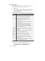
Command syntax and CLI rules
This document uses the following CLI command syntax
conventions:
•
Keywords are in bold text. For example:
ping
•
Values following keywords are in brackets. For example:
[interval]
•
Values that are position dependent and do not have
keywords are in arrows. For example:
<ip address>
•
Position independent arguments are shown in a vertical array
following the command. For example:
set accounting
primary_server <name_or_ip_address>
secondary_server <name_or_ip_address>
use_servers <ONE | BOTH>
•
A vertical character between two parameters indicates a
choice of two options. For example:
<true | false>
•
A series of commas between a set of choices indicates
multiple options. For example:
[login,network,callback,dial_out,manage,location]
Command completion
(
The command completion feature finishes spelling a unique,
abbreviated command parameter for you by pressing the
key. It is helpful when you’re in a hurry or uncertain how to
spell a command parameter.
2-12
Basic Installation and Setup
(
For example, if you type add ip n and press
, command
completion will spell out the keyword network without losing
your place in the command syntax. If the keyword is not
unique, you will get an error message.
Command retrieval
&
&
You can call back a n earlier command by pressing
p (Ctrl
p). You can also use
n (Ctrl n) to move forward to the next
command. Command retrieval works by consulting the history
of previous commands entered, which defaults to the last ten
commands.
Command reprint
&
This function is useful if you’re unsure what NETServer has
“seen” up to now. Use it by pressing
l (Ctrl l).
&&
&(
Command Line Editing
OO
U
Command line editing allows these options:
b (ctrl b) or
(left arrow) brings you go back one character;
b (ctrl b) or
(left arrow) brings you back one character;
f (ctrl f) or
(right arrow) takes you forward one character;
b (Esc-b)
takes you back one word;
f (Esc-f) takes you forward one
word;
a (ctrl a) takes you to the beginning of a command;
e (ctrl e) takes you to the end of a command and
k (ctrl
k) kills the line.
(
& &
&
Paused output display
When the NETServer outputs more information than your
screen can accommodate, you can use the following commands:
more (or carriage return) - continues output display
quit - cancels remainder of output display
Using general and positional help
The NETServer includes general and positional help to assist
you in determining the proper command syntax.
For general help, you can type the following command:
help <any command>
Basic Installation and Setup
2-13
NETServer provides a cursory list of associated commands and
their proper syntax. You can also get positional help while
entering a command by typing a question mark. The CLI
displays possible completions and returns the cursor to the last
point in the command before you entered the question mark.
First disable, then delete process
Many delete commands require that you first disable the process
or function. For example, commands to delete a network,
interface, route, TCP connection, community name, network
service must first be disabled.
Saving changes
You can save changes using the save all command. It is
important to remember that most commands may be accepted by
the NETServer when entered but are not necessarily enabled
until you use the save all command.
Running and stopping processes
NETServer encompasses many standard processes. These
processes are transparent to the user but administrators can run
them using the do command, or end them using the kill
command. This is useful for diagnostic or test purposes. Refer
to Chapter 9: Administrative Tools for more information.
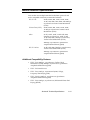
Using network services
The NETServer provides the following network services:
2-14
•
ClearTCPD - a daemon enabling ClearTCP access to a
modem group
•
SNMPD - an SNMP agent utilizing the UDP protocol
•
TELNETD - a TELNET daemon to access either the CLI or a
modem group
•
TFTPD - a TFTP daemon utilizing UDP on the server side
of the network to access files
Basic Installation and Setup
Using add and set commands
You can use the add and set commands to set and change
system parameters. These matched commands are functionally
related, but also differ dramatically. Table entries such as user,
interface, network, etc., require that you use the add command
to set the initial parameters. You can then use the set command
to change parameters that have been added.
Using list and show commands
You can use the list and show commands to view table entries
or detailed table entries. The list command displays a list of
table entries only, while the show command displays
information about a single line in a table or a set of scalars (nontable items).
Reset I-modem Interfaces
If you make changes to any I-modem port, you must reset the
port before the changes can take effect. This will close any
active connections.
For example:
set imod interface mod:1 call_type internet at_command ATZ!
Rebooting
The only change that requires you to reboot the NETServer is to
change its LAN port (eth:1) configuration. If you change the
configuration, you must save your work using the save all
command and type either reboot or shutdown.
Hardware Installation
You’re now ready to install the hardware.
If you want your NETServer Plus to sit on the desktop, continue
with the next section. If you plan to rack mount the unit, skip to
Installing on the Rack.
You’ll notice that the following illustrations are of V34 units. Imodem features may be arrayed differently but their
functionality is similar.
Basic Installation and Setup
2-15
Note: For desktop and rack mounting:
* DO NOT block the fan on the right side of the unit.
* Keep the unit in a dry place at room temperature.
* Keep the unit face up and level - don’t stand it on its side.
Installing on the Desktop
Carefully remove the NETServer Plus from the box and attach
the four rubber feet (supplied) to the recesses in the bottom of
the unit. The bottom panels of V.34 and I-modem units are
similar. See Figure 4 below.
Figure 4.
Bottom panel foot recesses
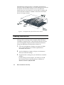
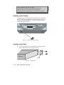
Installing on the Rack
1
Use the provided screws to fasten the two flanges to the
sides of the NETServer. See Figure 5 below.
Back Panel
Flange
Figure 5. Rack flanges
2-16
Basic Installation and Setup
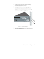
2
Gather four sets of nuts, bolts, and other mounting
hardware appropriate for your rack.
3
Holding the unit in the rack and supporting it from
underneath, insert each screw into the rails of the
equipment rack and loosely attach the corresponding
nuts/anchors. See Figure 6 on page 2-18.
Figure 6.
4
Screw/rail mounting
Once all 4 screws have been inserted, tighten beginning
with the two bottom screws.
Basic Installation and Setup
2-17
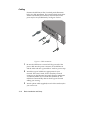
Cabling
Examine the NETServer Plus V.34 back panel illustration
below for cable installation. The I-modem back panel offers
similar functionality but I-modem, network and console
ports may be arrayed differently. See Figure 7 below.
Figure 7. Cable connections
2-18
1
Be sure the NETServer is turned off. Plug one end of the
power cable into the power connector on the NETServer
and the other end into a grounded AC outlet or power strip.
2
Attach the type of cable that is appropriate for your
network. There are Coaxial, UTP or Auxiliary network
connectors on the Ethernet rear panel, allowing attachment
via Thinnet (10Base-2) or Twisted Pair (10 Base-T). The
NETServer automatically detects which type of network
cabling you’re using.
3
Attach a phone cable (supplied) to each of the modem jacks
you want to use.
Basic Installation and Setup
Note: You may want to install a line noise filter/surge protector
between the power source and the NETServer. This protects the
NETServer and the data stored in it.
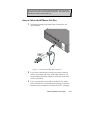
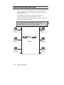
Setup to Talk to the NETServer 8/16 Plus
1
Attach the provided serial cable to the Console port. See
Figure 8 below.
Figure 8. Console/null modem cable connection
2
If you want to dial into the Console port, attach a modem
directly to the other end of the serial cable. Otherwise, use
the provided null modem adapter to attach the serial cable
to a PC or terminal.
3
If you connected the serial cable or modem to a PC rather
than a terminal, run a communications package or terminal
emulator (such as Windows Terminal) on the PC. Configure
Basic Installation and Setup
2-19
your communications software for 8 data bits, no parity and
1 stop bit.
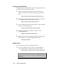
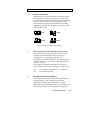
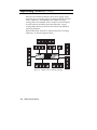
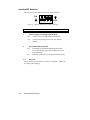
4
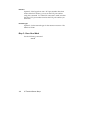
Examine the back panel of the NETServer. Find the lower
bank of dip switches (next to the NETServer Configuration
description) . Set DIP Switches 1 and 2 to a baud speed
setting of your choice. See Figure 9 below for options.
1
2
9600 bps
1
2
19800 bps
1
2
38400 bps
1
2
57600 bps
Figure 9. DIP Switch baud rate settings
Note: It isn’t necessary to change any V34 modem and I-modem
(upper bank) DIP Switch settings at this time.
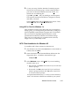
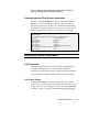
Using the CLI Quick Setup Program
You’re now ready to begin configuration.
If you want to use the CLI to configure your NETServer Plus,
we recommend you use the Quick Setup program on the CLI to
get the unit up and running fast. This program incorporates a
Wizard to help you step by step through the process. A script of
the Quick Setup follows: use it to jot down information you’ll be
prompted for.
Note: If you don’t want to use Quick Setup, skip to the next
section for manual configuration.
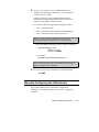
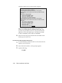
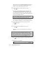
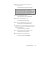
Power on the NETServer. The following prompt will appear:
NETServer>Welcome to the NETServer Quick Setup
The NETServer Quick Setup will let you set up simple
configuration for your whole system or different portions of the
system.
2-20
Basic Installation and Setup
Do you want to continue with NETServer Quick Setup?__
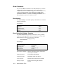
There are two ways to proceed: You can set up only the basic
configuration, which will allow you to continue with the Windowsbased Access Manager. Or you can configure a simple
configuration for both the LAN and WAN of IP, IPX, and
AppleTalk.
Do you want to configure only enough to use the GUI based
system [yes]?___
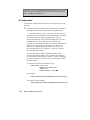
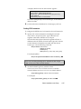
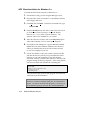
Please answer the following questions with "yes" or "no" to
indicate which portions of the system you want to configure.
When Quick Setup displays a question it will display a default
answer in square brackets, like "[yes]". If you simply press enter,
this is the answer that will be used for you.
Network management [yes]? __
IP [yes]? __
IPX [no]? ___
AppleTalk [no]? ___
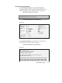
Quick Setup Identification information
>>> Enter the name of your system [ ]: ____________
>>> Who is the system contact person [ ]?____________
>>> Where is this system located [ ]?____________
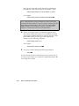
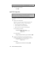
Quick Setup Management information
You can set up your system to require a user to log in via the
console or leave it so that the console is always in command line
mode.
>>> Do you want a log in required at the console [no]? ___
>>> Do you want to be able to manage the system via SNMP
[yes]? __
An SNMP community names a group of systems that can
manage your system via SNMP. It is a rudimentary form of
security.
Basic Installation and Setup
2-21
>>> What SNMP community will manage this system [public]?
____________
Along with a community name, you need to give the IP address
of the system using that community. "0.0.0.0" means any
system.
>>> What is the address of the station for this community
[0.0.0.0]? ____________
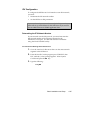
You also need to specify if this community can only read
information, or read and write information.
>>> Can this community change management information [yes]?
__
>>> Do you want to allow command line management via
TELNET [yes]? __
For TELNET management of the system you need to create a
user name and password to control access.
>>> What user name will be allowed to manage this system
[administrator]? ____________
>>> What password will be used for this user [ ]?___________
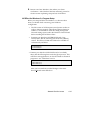
>>> Do you want to set up the syslog daemon [no]? ___
>>> What is the ip address of the syslog []? ____________
What level of information do you want logged to the syslog?
It must be one of the following: "common", "unusual", "critical".
>>> What level of logging do you want [unusual]? _________
>>> Would you like to set up radius accounting [no]? ___
>>> Enter the IP address of the primary radius accounting
server []? n.n.n.n
2-22
Basic Installation and Setup
>>> Would you like to set up radius authentication [yes]?__
>>> Enter the IP address of the primary radius authentication
server [n.n.n.n]? ___________
>>> What is the shared secret with this server []? _______
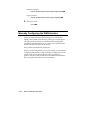
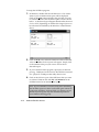
Quick Setup IP information
The NETServer uses a network name to identify the network for
future management commands.
>>> Enter the network name of your IP network [ip]: _______
>>> Enter the IP address for the NETServer [ ]:____________
The IP mask can be specified as a class ("A", "B", or "C"), the
number of one bits in the mask, or as an address in the format
255.x.x.x
>>> What should the mask be set to [C]? __
You need to specify the framing for the IP network. It should be
either "ethernet_ii" or "snap".
>>> What is the framing for the IP network [ethernet_ii]? ___
>>>Do you want to set up a default gateway [yes]? __
The default gateway gives the address of a router that the
NETServer will forward packets to when it has no other route to
their destination. It cannot be the same address as the IP
address for the NETServer.
>>> Enter the IP address of the default gateway [ ] ?
____________
The metric or "hop count" tells the NETServer how far the
default router is from the NETServer.
Basic Installation and Setup
2-23
>>> What metric should be applied to the default gateway [1]?
___
>>> Do you want to configure DNS for this Netserver [yes]?
>>> What is the address of the main DNS server for this
Netserver [ ]? ________
>>> What is the default DNS domain name for this Netserver
[ ] ? _____________
You can either assign each user his or her own address or you
can set aside a pool of addresses for dynamic allocation.
>>>Do you want to set up an address pool [yes]? __
The address pool is a continuous range of addresses.
>>>What is the initial address in the pool []? __________
>>>How many addresses should be in the pool [16]? ______
It is possible to restrict access to the TFTP server to a specific
system or a list of systems. Quick Setup will allow you to enter
one system that is allowed or allow all systems access.
>>>Do you want to allow all systems to access the TFTP server
[no]?___
>>>From what IP address will you allow access to your TFTP
network server [ ]? __________
IP setup is completed.
Quick Setup IPX information
The network name is used by the NETServer to identify your IPX
network
>>> Enter the name of your network [ipx]: ____________
The network number is a non-zero hexadecimal number of up to
8 digits.
>>> Enter the ipx network number [ ]:____________
2-24
Basic Installation and Setup
You need to specify the framing for the IPX network. It should be
one of the following: "ethernet_ii", "snap", "dsap", "novell_8023."
>>> What is the framing for the IPX network [ethernet_ii]? ___
You can either assign each user his or her own address or you
can set aside a pool of addresses for dynamic allocation.
>>>Do you want to set up an address pool [yes]? __
The address pool is a continuous range of addresses.
>>>What is the initial address in the pool []? _______
>>>How many addresses should be the pool [16]?_______
Quick Setup AppleTalk information
The network name is the name by which the AppleTalk network
will be identified and configured in the future.
>>> Enter the name of your AppleTalk network [appletalk] :
____________
All AppleTalk addresses should be between 0 and 65280.
>>> Enter the start of the network range [ ] : _____
The end address must be greater than or equal to the start
address. If the start address is zero, the end address must also
be zero.
>>> Enter the end of the network address [ ] : _____
>>> Enter the default zone name [ ] : ____________
>>> Would you like to enter more zone names [no]? : ___
You need to specify the default AppleTalk network range of the
router on the other "side" the WAN. This must be the same as
configured for the other router.
>>> Enter the start of the network range of the other router [ ] :
_____
Basic Installation and Setup
2-25
>>> Enter the end of the network range of the other router [ ] :
_____
Would you like to review your current settings before executing
[yes]? __
Identification Information:
System Name:
____________
System Contact:
____________
System Location:
____________
Management Information:
Console Login::
____________
SNMP Management:
SNMP Community:
____________
SNMP IP Address:
____________
SNMP Read&Write:
____________
TELNET Management:
User name:
____________
Password:
____________
Syslog Daemon:
Syslog IP Address:
____________
Syslog Level:
____________
Radius Accounting:
IP Address:
____________
Radius Authentication:
IP Address:
____________
Radius Secret:
____________
IP Information:
IP Network Name:
____________
IP Network Address:
____________
IP Mask:
2-26
Basic Installation and Setup
____________
IP Frame Type:
____________
IP Def Gateway Addr:
____________
IP Def Gateway Metric:
____________
DNS Server Information:
DNS Server Address:
____________
DNS Server Domain Name:
____________
IP address pool:
____________
IP pool address:
____________
IP pool size:
____________
IP WAN Information:
TFTP Client Information:
TFTP Access:
____________
IPX Information:
IPX Network Name:
____________
IPX Network Number:
____________
IPX address pool:
____________
IPX pool address:
____________
IPX pool size:
____________
Do you want to change any answers [no] __
Do you want to actually execute these commands [yes]? __
NETServer>
NETServer configuring networks......
Configuring Network Services.....
Starting the CLI......
Command Line Interpreter Started - Please Wait...
NETServer system configuration complete......
Configuring default Network Services (telnet and tftp).....
Basic Installation and Setup
2-27
Setting Up the I-modems
Unlike V.34 modems, each I-modem must be configured before
you can use them. Follow the steps below.
1.
Taking the information given you by your local telephone
company, specify the interface name (mod:1, mod:2, etc.) ,
switch protocol type, SPIDs and directory numbers.
Note: If you check the back panel, you’ll notice there are two
interfaces per connector. You can select only one switch type per
connector but a SPID (European customers disregard) ,
directory number and TEI for each interface (mod:1/mod:2) on
that connector.
It’s unlikely you’ll have to change terminal end type (TEI) and call
type values from the factory defaults. TEIs are assigned only by
your telco: if you telco supports PPP, the TEI is 0, if it supports
Multilink Protocol, set the value given you.
The auto call type (default) option chosen by default will
automatically handle whatever call you choose to make.
Providing an AT command string is not necessary at this time.
Use the following command to configure each I-modem:
set imodem interface <interface_name>
at_command <string>
call_type [auto | clear | internet | modemfax | v110 | v120]
directory_number <string>
spid <string>
switch [att | dms100 | ni1 | euro-isdn]
terminal_endpoint_id <string>
For example (abbr.):
set imod mod:1 dir 551000 spid 0555100001 swit ni1
2.
When the Switch Settings screen appears, check your
configuration to be sure it’s correct. If not, go back to step 1.
3.
Save each I-modem’s configuration to its FLASH memory
with an AT&W command. (Repeat for each I-modem.) Type:
set imodem interface mod:1 at_command at&w
2-28
-
Basic Installation and Setup
-
4.
Reset each I-modem by issuing an ATX! command. Your
new configuration won’t take effect until you do so. Type:
set imodem interface mod:1 at_command ATZ!
-
When the LEDs start blinking green, an ATI12 command is
sent to the I-modem, responding with a configuration
report. Watch the I-modems’ LEDs closely. They should
follow this pattern:
LED Status
State
Blinking Amber (8 per second)
Searching for U interface
Blinking Amber (1 per second)
Searching for S/T interface
Blinking green (1 per second)
Physical connection active
Off
Ready to make or receive calls
These are error conditions and suggested solutions:
Blink red (1 per second)
Incorrect SPID. Check the SPIDs
given to you against the ATI12
report sent back by the I-modem.
Solid red
No physical connection. Make sure
the U-interface cable is plugged into
the Telco-ISDN port.
Reminder: Whenever you change any I-modem setting, be sure to
issue AT&W and ATZ! commands immediately afterwards to
save the change and reset the I-modem. For further information
on using the set imodem interface command, see Chapter 9:
Administrative Tools in this manual and the set imodem interface
command in the CLI Reference Guide.
Setting Up the System Manually
This section describes how to manually set up your system. If
you want to use our Windows-based NMP application, refer to
the NETServer Plus Wizard Planning Guide for instructions.
Basic Installation and Setup
2-29
To begin manual configuration:
1.
Power on the NETServer. The "NETServer>" prompt
appears. When you’re prompted by the Quick Setup
Program to continue, type: no
2.
Name your NETServer and specify additional system
information. The name you enter serves as the NETServer's
DNS name and SNMP system name. The name will also be
the name that the NETServer advertises in SAP broadcasts.
The name must be unique - no other device on your
network can share it. You should also indicate the following
information:
•
location - where the NETServer actually resides
•
contact - the person to contact about NETServer issues
Use the following command:
set system name <“NETServer name” (up to 64 characters)>
location [“system site”]
contact [“contact information”]
-
You can enter the command all at once or in separate
commands. For example:
-
set system name “total control” location "boston" contact
“Keyser Sosay @ 508 123-4567 666x”
Or you can type:
--
set system name “total control”
set system location "boston"
set system contact " Keyser Sosay @ 508 123-4567 666x”
3.
-
Optional. Set the system date and time using this command:
set date <dd-mon-yyyy> time <hh:mm:ss>
-
For example:
set date 01-jan-2001 time 01:01:01
Note: If you plan to use our Windows-based NMP application to
manage your NETServer, continue. If not, skip to step 4.
2-30
Basic Installation and Setup
4.
Optional. If you plan to use an SNMP application to
configure and manage the NETServer, you must specify
SNMP community values.
SNMP community names segregate administrative
management groups and should match the community
settings of your generic SNMP software.
You must set the following SNMP community values:
•
name - community name
•
address - IP address of the Windows SNMP manager
•
access - either read-only or read-write access
Note: To retain a public community with read-only
privileges, assign the address to any station (0.0.0.0.).
To add the SNMP community values, use this command:
add snmp community <name>
address <IP address>
access [RO | RW]
-
For example:
add snmp com mis add 192.77.202.30 acc rw
Note: Command keywords can be abbreviated, as long as
they are unique to the command.
5.
Save your work. This command saves to flash memory.
save all
-
Manually Configuring the LAN Interface
This section describes how to manually configure the
NETServer's LAN interface (eth:1) for IP, IPX or AppleTalk
networks.
Basic Installation and Setup
2-31
Important: Even if your network uses only the IPX protocol, you
must still set up an IP address for the NETServer if you want to
use our NMP or an SNMP later.
IP Configuration
To manually configure the NETServer's LAN interface on an IP
network:
1.
Enter IP Network information. The network address consists of
the station address and a subnet mask using this format:
nnn.nnn.nnn.nnn/A, B, C, H, 8-30 or nnn.nnn.nnn.nnn
The first four octets describe the IP station address, followed
by the subnet mask (contiguous) designator. You can
specify the subnet by class, numerical designation or in the
IP address format. If you specify a Class C mask, for
example, this command will generate a 255.255.255.0 subnet
value for you. If you specify the number of 1 bits in the
mask, the acceptable range is 8-30 (or 8-32 if a host). For
help counting the bits, see Appendix C: Addressing Schemes
for a handy bitmask table.
The network address will be considered invalid if the
portion of the station address not covered by the mask is 0,
or if the station address plus the mask is -1 (all 1's). Defining
a numerical subnet is useful when your classification falls in
between classes.
To enter the IP network information, type:
add ip network <network name>
address <station address/mask>
interface [eth:1]
frame [ETHERNET_II | SNAP]
-
For example:
add ip net backbone add 192.75.202.99/C int eth:1 fra ethernet_II
A numerical mask example:
add ip net backbone add 192.75.202.99/24 int eth:1 fra ethernet_II
2-32
Basic Installation and Setup
Note: To verify your network settings, use the list networks
command. You can also check the connection by using the ping
<ip address> command.
2.
Set a default gateway. If the NETServer does not know where
to send a packet, it forwards the packet to the default
gateway or router addressed in this step. Default gateways
must be on the same subnet as the NETServer.
You also need to supply a metric (hop count) for each type of
default gateway. Possible values range from 1 (default) to
15. Note that since the actual metric of a default gateway is
only 1 hop, the value entered here is used to control the
perceived cost of the gateway to other routers on your
network. For example, a high metric will limit the number
of hops that the route is broadcast and may cause other
routers to see it as a less preferable route.
If the NETServer is configured to listen for IP default route
the IP Default Gateway can be overridden by a default route
broadcast with a lower hop count.
To add the default gateway, use the following command:
add ip defaultroute gateway <defaultrout gateway ip address>
metric <integer>
For example:
add ip defaultroute gateway 192.75.202.40 metric 1
-
Note: Check the default router setting with list ip routes.
Important: If you want to use a Domain Name Server (DNS),
continue below. If not, skip to step 6.
3.
Specify the IP address of the server you want to function as
the DNS server. The DNS server translates your host names
into their corresponding IP addresses - when queried - and
saves that information in its local host table.
NETServer supports one name service only - DNS. You can
name up to ten DNS servers using the command shown
Basic Installation and Setup
2-33
below but you must also specify the order you prefer they
be employed. This value is the preference number. Type:
add dns server preference <number> address <ip address>
For example:
add dns server preference 1 address 192.75.222.182
-
Note: The DNS server is only consulted to resolve host names
not found in the hosts table. If you are using a name service, the
hosts table may be left empty. Also, you may use the resolve
name command to learn DNS host names or numbers. See
Chapter 9: Administrative Tools for more information.
4.
Specify your default domain - the Ethernet segment where
your system resides and where you are defaulted to should
you forget to name the DNS server. Adding this entry to the
Hosts Table avoids you having to always specify the
domain. Use the following command:
set dns domain_name <string>
For example:
set dns domain_name usr.com
5.
-
Save your work by entering the following command:
save all
-
If your network does not use the IPX protocol, you may now go
to Configuring a Manage User; otherwise complete the steps in the
IPX Configuration section.
2-34
Basic Installation and Setup
IPX Configuration
To configure the NETServer's LAN interface on an IPX network,
you must:
•
Determine the IPX network number
•
Set the NETServer IPX parameters
Important: Even if your network uses only the IPX protocol, you
must still set up an IP address for the NETServer if you want to
use our NMP software or SNMP application later.
Determining the IPX Network Number
If your network uses the IPX protocol, you must first enter the
IPX network number of the segment connected to the
NETServer's LAN port. You can find this network number
using the Novell CONFIG utility.
For File Servers Running Novell Version 3.xx
1.
Go to the console of a file server that is on the same network
segment as the NETServer.
2.
From the Novell Console program press CTRL-ESC, then
ESC, until the : (colon) prompt appears. Select System
Console and press the
key.
3.
Type the following:
config
-
-
Basic Installation and Setup
2-35
A display similar to the one shown below appears:
File server name: USR_SERVER_ONE
IPX internal network number: 0000000A
Western Digital Star EtherCard PLUS Driver v2.05 (910424)
Hardware setting: I/O Port 300h to 31Fh, Memory CC000h to Cffffh,
Interrupt Ah
Node address: 0000C0488D28
Frame type: ETHERNET_802.3
Board name: TENBASE_802.3
LAN protocol: IPX network 00000255
Western Digital Star EtherCard PLUS Driver v2.05 (910424)
Hardware setting: I/O Port 300h to 31Fh, Memory CC000h to Cffffh,
Interrupt Ah
Node address: 0000C0488D28
Frame type: ETHERNET_802.2
Board name: TENBASE_802.2
LAN protocol: RPL
LAN protocol: IPX network 00000684
This is an example of the information returned for one
version 3.xx card that has two different frame types. The
card has one port address, but two LAN protocol network
addresses, one for each frame type. The network number
for 802.3 is 00000255, and for 802.2 it is 00000684.
4.
Write down the LAN protocol IPX network number for the
frame type you want to use.
For File Servers Running Novell Version 2.xx
1.
Go to the console of a file server that is on the same network
segment as the NETServer.
2.
Press CTRL-ESC until the : (colon) prompt appears.
3.
Type the following:
config
2-36
-
Basic Installation and Setup
A display similar to the one shown below appears:
LAN A Configuration Information:
Network Address: [0788] [002608C0D53F4z]
Hardware Type: [3Com 3C505 EtherLink Plus (Assy 2012 only)
V2.30EC (880813)]
Hardware Setting: IRQ=5, IO=300h, DMA 5
The above example only has one frame type, so the network
address is 0788.
4.
Jot down the network address for a frame type you’ll use.
Setting IPX Parameters
To configure the NETServer's LAN interface for an IPX network:
1.
Specify IPX network information including the network
name, address, interface and frame type of the network
segment connected to NETServer’s LAN port.
Note that the same physical network segment will have a
different network number for each frame type used. Be sure
to enter the network number associated with the chosen
frame type. Use the following command:
add ipx network <network name>
address [ipx address]
interface [eth:1]
frame [ethernet_ii | snap | dsap | novell_8023]
For example (abbr.):
add ipx net segment2 add 00000576 int eth:1 fra ethernet_ ii
-
Note: You can omit preceding zeros - NETServer will accept
“576” as the correct IPX network number.
2.
Set the IPX default gateway with the format
xxxxxxxx.xx:xx:xx:xx:xx:xx where xxxxxxxx is the IPX
network address and xx:xx:xx:xx:xx:xx is a MAC address.
set ipx default_gateway <network number.mac address>
For example:
set ipx system default_gateway 11.11.01.11.00.11
-
Basic Installation and Setup
2-37
Note: To verify network settings, use list networks command.
3.
Save your work by typing:
save all
-
AppleTalk Configuration
Important: Even if your network uses only the AppleTalk
protocol, you must still set up an IP address for the NETServer
if you want to use our NMP program or SNMP later.
To configure the NETServer's LAN interface for an AppleTalk
network:
1.
Specify network information.
The address range is the range of nodes from start to end
address, expressed as <sss-eee>. The start address:
•
Can only be 0 if the end address is 0
•
Can be 1-65280, as can the end address
•
Must be less than or equal to the end address
Use the following command:
add appletalk network <network name>
address_range <number of nodes>
interface <eth:1>
For example (abbr.):
add apple network pixie address_range 1-5 interface eth:1
2.
Provide zone information. Be aware that the first zone
specified is the default zone. Use the following command:
add appletalk zone <zone_name,zone_name …>
network <name>
For example:
add appletalk zone west,east,south network pixie
2-38
Basic Installation and Setup
-
-
3.
Enable the network by typing the following command:
enable appletalk network <name>
For example:
enable appletalk network pixie
-
Note: Verify network settings with list appletalk networks.
4.
Save your work by typing:
save all
-
Configuring a Manage User
This section describes how to create an administrative user with
manage privileges to establish a secure, centrally administered
NETServer. You can configure a remote login user, or, if you
prefer to dial in to the NETServer, you can create a manage user
locally through the NETServer console port - you can not do so
via TELNET at this point in configuration.
1.
Create a manage user. You have these options:
•
If you want the manage user to login to the NETServer,
use the command below, set the type to manage,login
and login service (Telnet is the default service; make a
choice only if you want to choose Rlogin or ClearTCP).
Then go to step 2.
•
If you want a manage user to access NETServer via a
dial-in (network) connection, use the command below.
The network service default is PPP; if you want to
select another option, add it. When finished adding a
user locally, skip to step 3.
add user <"user name">
network_service [ARAP | PPP | SLIP]
password [password]
type [LOGIN,NETWORK,CALLBACK,DIAL_OUT,MANAGE]
Basic Installation and Setup
2-39
Network example:
add user predator password aliens type manage,network
Login example:
add user predator password aliens type manage,login
2.
-
-
Save your work.
save all
-
Manually Configuring the WAN Interface
Setting up a protocol over the WAN begins by creating and
editing a user profile. With the user profile you can specify the
call type, protocols, addresses, and bandwidth management
parameters that determine how you connect and communicate
to that user (remote site) over the WAN.
User profiles are detailed in chapters 4-7.
When you save user profiles you’ve just created, you’re finished
configuring the NETServer side of the link. Configuration of the
router on the remote side of the link will vary with your
product, but set up will include the local NETServer IP address.
See your product manual for more information.
2-40
Basic Installation and Setup
Chapter 3
Configuration Overview
The NETServer 8/16 Plus lets you manage and configure the
NETServer by typing commands. The configuration
information that you set using these commands is stored in a
number of tables that reside in the NETServer flash memory.
This chapter includes the following sections:
• Setting Up NETServer 8/16 Plus Applications
• Configuration Command Overview
• Configurable Table Overview
Setting Up NETServer 8/16 Plus Applications
The NETServer 8/16 Plus is designed to perform four basic
applications. Refer to the appropriate chapter for more
information:
•
IP terminal service (see Chapter 4)
•
Network dial-in access (see Chapter 5)
•
Dial-out access (see Chapter 6)
•
LAN-to-LAN routing (see Chapter 7)
Configuration Overview
3-1
Configuration Command Overview
NETServer configuration data is stored in several tables, (User
and Interface tables, e.g.). You can change most parameters in
these tables using the generic set command:
set [user | interface | system | etc.] <parameter name> <value>
For example:
set user maximillian message “Mexico is Mine”
Most objects, like interfaces and users, must be created before
they can be configured. Use the generic add command:
add [user | interface | filter | etc] <name>
Anything that you can add can also be deleted. Use the generic
delete command:
delete [user | interface | filter | etc.] <name]
You can view current configuration information with either the
show or list command. For example:
show network backbone
show user John
show ipx settings
list networks
list ipx services
list users
A complete list of commands and options may be found in the
CLI Reference Guide. Also, help for these commands is available
online using the help command. For example:
help set user
3-2
Configuration Overview
Configurable Table Overview
This section briefly describes some of NETServer’s internal
databases, or tables, which contain configuration information.
Interface Table
This table contains information about all NETServer interfaces,
including modem ports and the Ethernet interface.
User Table
This table contains authentication and configuration information
for five types of users: Login, Network, Callback, Dial out, and
Manage users.
Login
Login users are remote users dialing in to request
terminal service from an IP host. Once such a user is
authenticated, he or she is connected to a host with a
login service such as Telnet or Rlogin
Network
Network users are remote users dialing in to become
a virtual node of the local network. Such a user may
be an individual attaching to the network or an entire
LAN dialing in to route packets onto the local
network
Callback
Callback users are remote users who dial into the
NETServer. Once the user is authenticated, the
NETServer disconnects and dials users back, using a
pre-defined telephone number
Dial out
Dial out users are local or remote users who singly
login then connect to a remote host
Manage
Manage users have administrator-level privileges
Note: User table entries override the settings for the interface the
user is connected to.
Configuration Overview
3-3
Facilities Table
You can check the this table to judge system performance. The
Facilities Table contains each NETServer event facility and its
associated log level. Each facility generates unique event
messages during processing which can be sent to a syslog server
you define.
Facilities are configurable in that you can change log levels from
the defaults shown below. Available log levels are: debug,
verbose, common, unusual and critical, with critical being the most
severe event. For more, refer to Appendix D, Event Messages.
Hosts Table
This table contains a list of local hosts. The table is used to
translate names to IP addresses and vice versa. This allows
users and administrators to type host names rather than
addresses.
The Hosts Table is especially useful if your network does not
have a name service such as DNS. If your network has a name
server, the NETServer first tries to match the host name with an
IP address using the Hosts Table before using the name server.
Note that IPX networks do not use this table since SAP
automatically provides the functionality of a name service.
Initialization Script Configuration Table
This table contains serial interface initialization scripts sent to a
modem each time the port is reset (a modem resets itself every
time it disconnects).
Initialization scripts for modems will probably contain the AT
commands needed to configure them for use on your network.
Module Table
This table contain information used by processes or management
features that run in the background. Display a list of these items
using the list processes command.
3-4
Configuration Overview
Network Table
This table contains all generic protocol information entered
through the add (ip, ipx and appletalk) network command.
Filter and Associated Tables
Filters may be created to control packets you permit to pass
through given interfaces. You can create filters that work on a
per-user or per-interface basis. Filters that you create are stored
in the Filter Table. Also, the Access Filter Table determines
whether user filters take precedence over interface filters.
Routes Table
This table contains static and dynamic routing information.
Dynamic routes are updated by broadcasts received from other
routing devices on the network using routing protocols such as
RIP, IPX RIP, SAP, and RTMP. Static routes are added to the
table by hand. A static route to a given site will override a
dynamic route.
Static routes to a given site are required when the site is not
running a dynamic routing protocol or when the NETServer is
not listening for dynamic routing protocol broadcasts on the
given interface. Without dynamic routing protocol messaging,
the NETServer cannot gather information on the location of
other routers, gateways, and remote hosts and must know
exactly where to send a packet.
SNMP Configuration Tables
The NETServer provides support for the Simple Network
Management Protocol (SNMP) version 1 and industry standard
MIB-II variables. These variables are fully described in your
MIB-II documentation.
The SNMP Community Table stores information about which
SNMP servers (if any) are permitted to make SET and GET
requests, as well as Read and Write Communities.
The SNMP Trap Community Table saves names and addresses
of trap communities.
Configuration Overview
3-5
Syslog Table
This table contains IP addresses of syslog hosts to which event
messages are sent. You can define multiple syslog hosts that
record event messages by the message's log level.
3-6
Configuration Overview
Chapter 4
IP Terminal Server Setup
Remote users can dial into the NETServer 8/16 Plus to establish
a terminal session with a host on the local network using a login
service such as Telnet, Rlogin, or ClearTCP. See Figure 1 below
for a sample network topology.
TTY (Terminal) Data
Remote Office
User
PSTN/
ISDN
NETServer
Host
Telnet, Rlogin
ClearTCP
Mobile User
Host
Figure 1. .IP Terminal Server Topology
IP Terminal Server Setup
4-1
Configuring the Remote Computer
Remote terminal users are known as login users in the
NETServer system. The NETServer system administrator should
provide the remote login user with the following information:
• A user name and password
• A telephone number for the NETServer
• Login host address or name
The remote computer should be configured for the following
communications parameters:
• 8 bits, no parity, and 1 stop bit
• Hardware (RTS/CTS) flow control
• Normal Carrier Detect
Note: These settings are the defaults. If you change the
NETServer's communications settings, you must provide the
remote user with the appropriate settings as well. See the CLI
Reference Guide for more information.
4-2
IP Terminal Server Setup
Configuring Login Hosts
For a login host to be available to a login user, you must define
it in the NETServer login hosts table. This table contains the
host name, address, selection preference, and login service port
for each login host.
Note: To allow the user to access a login host using a host name,
you must first configure a DNS server using the add dns server
command. For example:
add dns server 7.7.7.7 name boston preference 1
To set up login host table entries in the NETServer:
Step 1 - Configure Login Hosts
Add as many hosts as necessary to support your login users.
Use the following command:
add login_host <host_name>
address <ip_address>
preference <number>
rlogin_port <TCP_port_number>
telnet_port <TCP_port_number>
clearTCP_port <TCP_port_number>
Host Name
Name of the login host.
Address
Optional. This is the IP address of the login host. If you specify
an IP address here, it will be added to the DNS host table. If
you do not specify an address, the NETServer will consult the
DNS server to resolve the address.
Preference
Priority for the login host. The preference number must be
unique for each host entry.
IP Terminal Server Setup
4-3
Rlogin Port
Optional. The Rlogin port number of the host.
Telnet Port
Optional. The Telnet port number of the host.
ClearTCP Port
Optional. The ClearTCP port number of the host.
For example:
add login_host detroit address 6.6.6.6 preference 1
Step 2 - Check Your Work
Check you host entries using the following command:
list login_hosts
Each login host you add that includes a name and IP address is
also added to the NETServer DNS host table. To display a list
DNS hosts, use the following command:
list dns hosts
Step 3 - Save Your Work
Use the following command:
save all
4-4
IP Terminal Server Setup
Configuring Login Users
Remote login users can use login services such as Telnet, Rlogin,
or ClearTCP by dialing into the NETServer. Login users can
connect directly, or be configured as callback users, meaning the
NETServer will call the user back at a phone number specified
in their user profile.
You can configure the user to use a specific login service and
access a specific login host, or you can configure the user to
determine the login service and login host.
Note: You can also specify login user information in RADIUS.
When RADIUS authenticates a user, it can also pass on user
configuration information to the NETServer. For more
information, refer to Appendix E, RADIUS Authentication
and Accounting.
To configure a login user:
Step 1 - Add the User
Use the following command:
add user <name>
password <password>
login_service [rlogin | telnet | cleartcp]
type [login | lnetwork | callback]
Password
Unique user password.
Login Service
Specifies the default login service. The default is Telnet. This
parameter can be one of the following:
Telnet
Supported by most TCP/IP computers,
Telnet lets the user log in to hosts that
support it.
IP Terminal Server Setup
4-5
Rlogin
Although Rlogin was originally a UNIX
protocol, it is now supported by some nonUNIX machines as well. Unlike Telnet,
Rlogin allows a user logged into a host to
access their accounts on other (trusted) hosts
without re-entering a password.
ClearTCP
Unlike Telnet and Rlogin, ClearTCP is not
actually a login service, it is a direct
connection to a given TCP port number. 8-bit
data is exchanged without interpretation.
Note: The host type setting may override this setting. See step 2
for more information.
Type
Valid types for a login user are:
•
login
•
login,callback
If you include callback in the user type, you need to specify a
phone number at which the user is called back using the
following command:
set user <name> phone_number <number>
Tip: At this point, it may be helpful to use the show user
command to display the user's default parameters. This allows
you to decide which parameters you need to set, and which
parameters you can leave as defaults.
4-6
IP Terminal Server Setup
Step 2 - Configure Login User Parameters
Use the following command:
set login user <name>
host_type [prompt | select | specified]
login_host_ip_address <ip_address>
login_service [rlogin | telnet | cleartcp]
tcp_port <port_number>
terminal_type <string>
Host Type
Determines how the user is connected to a login host. The
default is select.
prompt
If the user is prompted, this setting overrides
the login service setting. At the prompt, the
user can enter the login service (for example,
Telnet) and the host name or address, or
"connect" and the host name or address to
use the default login service
select
(Default) The user is automatically connected
to the host defined in the Login Hosts Table.
The method of selecting the host is set using
the set connection command (RANDOM or
ROUND ROBIN).
specified
The user is connected to the host specified in
the login_host_ip_address setting
Login Host IP Address
If the login user's host type is specified, you must enter the IP
address for the host to which they will connect.
Login Service
Specifies the default login service. See Step 1 for details.
IP Terminal Server Setup
4-7
TCP Port
Optional. If the login host uses a TCP port number other than
23 (the default for Telnet), you can set the TCP port number
using this command. For ClearTCP connections, make sure that
the host's TCP port number matches the TCP port number you
enter here.
Terminal Type
Optional. Set the terminal type for the remote connection. The
default is VT100.
Step 3 - Save Your Work
Use the following command:
save all
4-8
IP Terminal Server Setup
IP Terminal Service Case Study
This section provides an example how to configure a login user
to dial-in to the NETServer and establish a Telnet session with a
host machine on the network. The user will be prompted for the
login service and host address.
Figure 2 below depicts the remote terminal connection for a user
named Jack to the corporate LAN. Jack's home computer uses
VT100 terminal emulation software to establish a IP terminal
session with any host on the LAN that he is authorized to
access. In this example, Jack will use Telnet to access a host
named "quartz".
Jack's
Computer
Telnet
PSTN
VT100 Terminal
Emulation
(8 bits, no parity, 1 stop bit)
NETServer
Login Host
Quartz
195.112.133.2
Telnet
Login Host
Granite
195.112.133.10
Figure 2. IP Terminal Service Example
Note: Many of the commands and keywords shown in this case
study are abbreviated. For detailed information about
command syntax, refer to the CLI Reference Guide.
IP Terminal Server Setup
4-9
Assuming that a DNS server is already configured for the
NETServer, follow these steps to configure the login host and
login user:
1.
Add a user called jack with the password agent86 that is a
login user type.
add user jack password agent86 type login
2.
The login host that Jack will access has not been added yet.
This host is the one that most users will be logging into on a
daily basis, so set the preference to "1".
add login_host quartz address 195.112.133.2 pref 1
3.
We want Jack to be able to enter the login service and host
name at the NETServer command prompt.
set login user Jack host_type prompt
4.
Save your work.
save all
When Jack dials in to the NETServer, he is prompted for his
login name and password. After he is successfully
authenticated, the system prompt appears.
At this point, Jack can connect to the host using the following
command:
telnet quartz
Since Jack's default login service is Telnet, he could also enter
the following command to connect to quartz:
connect quartz
When Jack ends his host session, he is returned to the system
prompt. He can access another login host, or he can exit the
NETServer command line by typing a valid exit command (bye,
exit, leave, quit).
4-10
IP Terminal Server Setup
Chapter 5
Network Dial In Access
The NETServer 8/16 Plus allows remote PC and Macintosh
users to dial in over analog or ISDN lines and connect to the
local network. The NETServer supports the following network
protocols:
•
Internet Protocol (IP)
•
Internet Packet Exchange (IPX)
•
AppleTalk Remote Access Protocol (ARAP)
The remote user can use one of the following protocols to
communicate with the network:
•
Point-to-Point Protocol (PPP)
•
Serial Line Internet Protocol (SLIP)
•
AppleTalk Remote Access Protocol (ARAP)
The NETServer provides the remote user with access to all
network services such as file servers, electronic mail, Internet
services, and printers as if the remote user were connected
locally to the network.
The NETServer V.34 supports 8 or 16 simultaneous analog
connections, while the NETServer I-modem supports 8 or 16
simultaneous ISDN or analog connections.
Network Dial In Access
5-1
Figure 1 below depicts the NETServer's remote network access
capabilities.
Internet
Remote Office
User
PPP, SLIP,
or ARAP
PSTN/
ISDN
NETServer
PCs
IP, IPX, and
AppleTalk
Mobile User
File
Server
RADIUS
Server
Figure 1. NETServer’s Remote Access Capabilities
5-2
Network Dial In Access
Overview
This section describes how to set the NETServer up to provide
remote access services to dial-in network users.
Configuring the NETServer for dial-in access simply involves
setting up a network user profile for each remote user. The
network user profile contains all of the information necessary
for the user to connect to the network, such as protocols, remote
addresses, and other unique settings.
NETServer configuration differs slightly depending on the
protocol (IP, IPX, and AppleTalk) the user will use to connect.
This section provides an overview of some of the protocolspecific information you will need to know.
IP Parameters
IP remote access sessions can use either the PPP or SLIP
remote access protocols. You can specify a unique IP
address, or you can configure the NETServer to simply
assign the user an address each time he or she dials in. The
address can also be negotiated by the NETServer and the
user’s machine.
You should know:
• The connection protocol (PPP or SLIP) that users will
employ
• The dial-in user’s subnet mask
• The MTU for PPP is 1500, and is negotiated between the
client and the NETServer. If the client uses SLIP, the
Maximum Transmission Unit (MTU) is 1006, and should
match on both sides of the connection
• Whether or not the dial-in user is configured with
TCP/IP (Van Jacobson) header compression
Network Dial In Access
5-3
IPX Parameters
You can configure the user profile to specify a unique IPX
network number that will represent the link between the remote
system and the local network for the duration of the connection,
or you can configure the NETServer to assign an IPX network
number from a pool.
You should know:
•
IPX remote access sessions must use the PPP protocol.
•
The MTU for IPX is 1500 and is negotiated between the
client and the NETServer
AppleTalk Parameters
AppleTalk remote access sessions use the ARAP remote access
protocol. The AppleTalk dial-in connection is treated like an
extension of the local LAN. The NETServer will negotiate a
station address on the dial-in user's behalf (AppleTalk station
numbers are dynamic) and provide a proxy-AARP service on
the LAN.
You should know:
5-4
•
You can specify a range of addresses within your LAN
network range that you want to make available for the
remote connection
•
The default ARAP MTU is 600 and is negotiated between
the client and the NETServer
•
AppleTalk uses Data Encryption Standard (DES)
authentication. DES is a National Institute of Standards &
Technology (NIST) encryption technique that scrambles
data into an unbreakable code for public transmission.
Network Dial In Access
Remote Computer Setup
The remote user’s computer must have a modem or ISDN
connection and communications software that supports the
remote access protocol that they are using (PPP, SLIP, or
ARAP). A protocol driver must be loaded on the remote user’s
computer for these types of connections.
Provide the user with a:
• User name and password
• Telephone number to access the NETServer
Some other considerations:
• If set to EITHER, the NETServer will auto-detect the remote
computer's PAP/CHAP settings and MTU size. NETServer
will attempt CHAP authentication first, then PAP.
• The remote computer may specify an IP address that will be
used for the session. If the NETServer is configured to
negotiate an IP address with the remote computer, it will
automatically detect this address.
Note: If the remote computer does not have an IP address
configured and the address selection type is negotiate, the
NETServer will terminate the call.
• The remote user can also configure the protocol that he or
she will use (for example, IP or IPX).
The remote computer should be configured for the following
communications parameters:
•
8 bits, no parity, and 1 stop bit
•
Hardware (RTS/CTS) flow control
•
Normal Carrier Detect
Note: These settings are the defaults. If you change the
NETServer's communications settings, you must provide the
remote user with the appropriate settings as well. See the CLI
Reference Guide for more information.
Network Dial In Access
5-5
Configuring Address Pools
If you want network users to be assigned an IP or IPX address
from a pool each time they connect, you must configure address
pools on the NETServer.
Configuring an IP Address Pool
To configure an IP address pool:
1.
Set the initial pool address:
set ip system initial_pool_address <ip_address>
2.
Set the number of pool members. The maximum is 8 or 16,
depending on the number of ports your NETServer has.
set ip system pool_members <number>
For example:
set ip system init 195.221.15.112 pool 16
Configuring an IPX Address Pool
To configure an IPX address pool:
1.
Set the initial pool address:
set ipx system initial_pool_address <ipx_address>
2.
Set the number of pool members. The maximum is 8 or 16,
depending on the number of ports your NETServer has.
set ipx system pool_members <number>
For example:
set ipx system init 100 pool 16
5-6
Network Dial In Access
Configuring an ARAP AppleTalk Address Pool
While a NETServer configures an ARAP AppleTalk address
pool by default, you can set a desired range of network numbers
to be included in this pool. For example, the default value of 0 0 can be changed to 1 - 1, allowing a user to be assigned a node
from network 1. The ARAP node network must be a subset of
the range defined for the LAN.
1.
Specify the range of network numbers you want the address
pool to span using the sss-eee format where sss is the
network number and eee the end of the range.
set appletalk arap_node_network_range [sss-eee]
For example:
set appletalk arap_node_network_range [1-1]
2.
Optional. You may specify the minimum and maximum
ARAP nodes configured for this pool. If you don’t set these
values, they default to 16. Use this command:
set appletalk max_arap_nodes_reserved <number>
set appletalk min_arap_nodes_reserved <number>
For example:
set appletalk max_arap_nodes_reserved 5
set appletalk min_arap_nodes_reserved 1
User Configuration Overview
You configure all remote networking parameters within the
profile of the user that is dialing in. A user profile specifies the
user's protocol, address parameters, and other unique settings.
Note: You can also specify network user information in RADIUS
(except AppleTalk users). For more information, refer to
Appendix E, RADIUS Authentication and Accounting.
Network Dial In Access
5-7
NETServer Defaults
A remote access user is defined as a network user in the
NETServer database. When you create a network user, the
NETServer builds an extensive user profile that includes many
default parameters. These defaults reflect most common types
of user configurations. This makes user configuration easier, as
you may only need to change a few parameters from their
default settings.
Note: When you add a network user, IP and IPX protocols are
enabled by default. AppleTalk is disabled by default (zones
must be entered before manually enabling the protocol). You
should disable any protocols that will not be used.
Remote Addressing Options
The options for assigning a network address to a remote user
vary according to protocol. The following table summarizes the
addressing options:
Network
IP
IPX
AppleTalk
Datalink
PPP
SLIP
CSLIP
PPP
ARAP
Addressing Options
From pool, negotiate, specify
From pool, negotiate, specify
From pool, negotiate, specify
From pool, negotiate, specify
Dynamically assigned
Network User Types
A network user can be one of the following types:
5-8
•
network - Access to network services only
•
network,login - Access to network or login services
•
network,callback - NETServer dials the user back and
provides access to network services only
•
network,login,callback - NETServer dials the user back and
provides access to login and network services
Network Dial In Access
Configuring an IP User
To configure an IP user:
Step 1 - Add the User
Create a standard network user, specifying the user's password,
type, and default network service. Use the following command:
add user <name>
password <password>
type [network | login | callback]
network_service [slip | ppp]
Password
Unique user password.
Type
A network user type can be one of the following:
•
network
•
network,login
•
network,callback
•
network,login,callback
Network Service
IP users can use either SLIP or PPP as their remote access
protocol. Choose one of the following:
slip
SLIP (Serial Line IP) provides remote access
support for IP only
ppp
PPP (Point-to-Point Protocol) provides
remote access support for IP and IPX
Network Dial In Access
5-9
Tip: At this point, it may be helpful to use the show user
command to display the user's default parameters. This allows
you to decide which parameters you need to set, and which
parameters you can leave as defaults.
For example, to add a network user employing PPP over IP,
type:
add user kay password howe type network network_service ppp
Step 2 - Specify a Remote Address
If you want to explicitly specify the network user's remote IP
address, follow the instructions in this step. If you want the
remote IP address to be selected from a pool or negotiated, go to
step 3.
Use the following command:
set network user <name>
address_selection specified
remote_ip_address <ip_address>
If you define the address selection method as specified, you
must also specify the remote IP address in the same command.
For example (abbr.):
set net user kay add spec rem 195.114.123.16
5-10
Network Dial In Access
Step 3 - Set the Address Selection Method
If the network user's address is not specified, you need to define
whether the user's remote IP address is assigned or negotiated:
set network user <name>
address_selection [assign | negotiate | specified]
assign
Configure an IP address from the IP address
pool, which is set globally using the
set ip system command (see Configuring an IP
Address Pool on page 5-6)
negotiate
PPP connections only. The remote computer
must have an IP address configured. The
NETServer tries to learn the remote
computer’s IP address using IPCP address
negotiation. If the remote computer does not
have an address configured, the user is
disconnected
For example:
set network user kay address_selection negotiate
Step 4 - Save Your Work
Use the following command:
save all
Continue with one of the following sections of this chapter for
more information on setting other network user parameters:
• Configuring PPP Parameters
• Configuring Additional Parameters
Network Dial In Access
5-11
Configuring an IPX User
To configure an IPX user:
Step 1 - Add the User
Create a standard network user, specifying the user's password,
type, and default network service. Use the following command:
add user <name>
password <password>
type [network | login | callback]
network_service ppp
Password
Unique user password.
Type
A network user type can be one of the following:
•
network
•
network,login
•
network,callback
•
network,login,callback
Network Service
Since only PPP can provide remote access support for IPX, and
is the default, there is no need to set the network service
parameter.
5-12
Network Dial In Access
Step 2 - Specify a Remote Address
If you want to explicitly specify the network user's remote IPX
address, follow the instructions in this step. If you want the
remote IP address to be selected from a pool or negotiated,
go to step 3.
Use the following command:
set network user <name> ipx_address <ipx_address>
For example:
set network user glenn ipx_address 100
Note: If the IPX address specified in a user's profile is in use
when the user dials in, the call will be dropped.
Step 3 - Set the Address Selection Method
When you create a network user, the default IPX address is set
to 00000000.
•
If the remote computer has an IPX address configured on it,
and an IPX address is not specified in the user profile, the
NETServer will negotiate the remote address.
•
If the NETServer cannot negotiate an IPX address an IPX
address will be selected from the pool, which is set globally
using the set ipx system command (see Configuring an IPX
Address Pool on page 5-6).
Network Dial In Access
5-13
Step 4 - Configure IPX Routing
Configure how you want the NETServer to handle IPX RIP and
SAP packets. The default is RESPOND.
set network user <name>
ipx_routing [all | listen | send | respond | none]
all
Detects, sends, and answers with RIP and
SAP packets
listen
Listens for RIP packets destined for this
NETServer's networks
send
Transmits RIP and SAP packets destined for
the remote system
respond
If requested, answers with IPX RIP or SAP
data
none
Ignores all routing packets (default)
Step 5 - Save Your Work
Use the following command:
save all
Continue to one of the following sections of this chapter for
more information on setting other network user parameters:
• Configuring PPP Parameters
• Configuring Additional Parameters
5-14
Network Dial In Access
Configuring an AppleTalk User
Unlike IP and IPX, AppleTalk dynamically assigns a station
address for the remote computer. An AppleTalk dial-in
connection is treated as an extension of the local LAN. The
NETServer negotiates a station address on the dial-in user's
behalf (AppleTalk station numbers are dynamic) and provides a
proxy-AARP service on the LAN.
Note: RADIUS does not support AppleTalk user authentication.
You must configure an AppleTalk user locally.
Step 1 - Add the User
Create a standard network user, specifying the user's password,
type, and default network service. Use the following command:
add user <name>
password <password>
type [network | login | callback]
network_service arap
Password
Unique user password.
Type
A network user type can be one of the following:
•
network
•
network,login
•
network,callback
•
network,login,callback
Network Service
AppleTalk users use ARAP as their remote access protocol.
Network Dial In Access
5-15
Step 2 - Set the AppleTalk Range
Specify the range of addresses within your LAN network range
that you want to make available for the remote connection:
set network user <name> range_appletalk_address <range>
Step 3 - Disable Zone Filtering (optional)
This setting determines the AppleTalk zones that the remote
user will see. By default, AppleTalk zone filtering is enabled,
which means that zone filtering occurs based on filter rules that
you defined in the filter file. Refer to Chapter 8, Packet Filters for
more information on creating and using filters.
You can disable zone filtering using the following command:
set network user <name> filter_zones disable
Step 4 - Save Your Work
Use the following command:
save all
Continue to the Configuring Additional Parameters on
page 5-18 for information on setting additional network user
parameters.
5-16
Network Dial In Access
Configuring PPP Parameters
If the remote user connects using PPP, you can also define
several PPP parameters that control how the remote access
session is handled.
Note: This section describes only the parameters that are
applicable for network dial-in users. Many of the configurable
PPP parameters are used for LAN-to-LAN routing only. These
parameters are described in Chapter 7, LAN-to-LAN Routing.
Use the following command:
set network user <name> ppp
compression_algorithm [ASCEND | AUTO | MICROSOFT |
NONE | STAC]
expansion_algorithm [CONSTANT | LINEAR]
min_size_compression [value from 128-1514]
receive_acc_map [hex_number - array of 4 bits]
reset_mode_compression [AUTO | EVERY_PACKET |
EVERY_ERROR]
transmit_acc_map [hex_number - array of 4 bits]
Compression Algorithm
Specifies which proprietary compression algorithm PPP should
use. Default: auto.
Expansion Algorithm
Specifies which type of expansion algorithm should be used to
decompress incoming PPP data. Default: linear.
Minimum Compression Size
Specifies the minimum size at which PPP compresses a packet.
Data packets smaller than this value are not compressed.
Default: 256.
Receive Asynchronous Character Control Map
Determines whether the NETServer uses the asynchronous
control character map to filter incoming data. Default:ffffffff.
Network Dial In Access
5-17
Reset Compression Mode
Determines how often PPP should examine packets to decide
when to re-negotiate the optimum compression algorithm.
Default: auto.
Transmit Asynchronous Character Control Map
Determines whether the NETServer uses the asynchronous
control character map to filter outgoing data. Default: ffffffff.
Configuring Additional Parameters
In addition to the protocol-specific parameters that you
configure for IP, IPX, and AppleTalk, you can also set several
standard network user parameters.
MTU
Determines the Maximum Transmission Unit (MTU), or largest
packet size the NETServer will accept. The default setting is
1514. PPP and ARAP connections will negotiate the MTU. For
SLIP, the MTU on both ends of the connection must match.
•
PPP - 1500 bytes
•
SLIP - 1006 bytes
•
ARAP - 600 bytes
Use the following command:
set network user <name> mtu <number>
PAP/CHAP Authentication
By default, the NETServer is configured globally to use either
PAP or CHAP authentication for PPP connections.
The default setting is either. When a user dials in, the
NETServer first tries to authenticate the user using CHAP. If
the remote computer does not respond, the NETServer attempts
to use PAP. If the remote computer doesn't respond, the
connection is dropped.
5-18
Network Dial In Access
Change the authentication setting by typing:
set ppp receive_authentication [chap | pap | either | none]
Phone Number
If the network user is a callback user, use the following
command to set the user's phone number. Note: this value does
not apply to other dialin users.
set user <name> phone_number <number>
Remote Access Case Study
In this case study, three network users are configured, one for
each protocol supported by the NETServer. The following table
lists the users we will create and provides a profile of each user.
User
Name
Profile
User_A
This IP user connects the NETServer using PPP.
After this user dials in and is authenticated using
CHAP, the call is disconnected and the user is
dialed back by the NETServer. This user's IP
address is negotiated.
User_B
This IPX user connects to the NETServer using
PPP and is authenticated using PAP. Once
authenticated, this user's IPX address is selected
from a pool.
User_C
This AppleTalk user connects to the NETServer
using ARAP, and is authenticated locally. This
user needs access to all AppleTalk zones on the
LAN.
Assumptions
This case study assumes the following:
• The NETServer has the correct IP address and netmask
• IP, IPX, and AppleTalk networks have been configured
Network Dial In Access
5-19
• All necessary protocols are enabled
• All other settings remain at factory defaults
Configuring User_A
To configure User_A:
1.
Add a user called "User_A" that is a network/callback user
type (the password is the same as the user name):
add user User_A password User_A type network,callback
Note: The default network service for any network user that you
add is PPP. Therefore, there is no need to set the network
service parameter for this user.
2.
Enter the phone number at which the NETServer calls the
user back:
set user User_A phone 5085524438
3.
User_A's home PC has an IP address configured on it. The
NETServer will detect this address by setting the address
selection method to negotiate:
set network user User_A address_selection negotiate
4.
Save the changes to flash memory. Type:
save all
Note: By default, the NETServer will autodetect the
authentication method the remote computer is using (CHAP or
PAP). The NETServer will first attempt CHAP, then PAP
authentication. If the remote computer does not support one of
these methods, the call will be dropped.
Configuring User_B
User_B's configuration is simple, since he uses the NETServer
defaults to connect remotely. To configure User_B:
5-20
Network Dial In Access
1.
Add a user called "User_B" that is a network user type (the
password is the same as the user name):
add user User_B password User_B type network
Note: The default network service for any network user
that you add is PPP. Therefore, there is no need to set the
network service parameter for this user.
2.
User_B's IPX address will be assigned from a pool.
Configure the address pool using the following command:
set ipx system initial_pool 100 pool_members 8
Since we didn't change User_B's default IPX address, it will
automatically be selected from the pool.
3.
Save the changes to flash memory. Type:
save all
Configuring User_C
To configure User_C:
1.
Add a user called "User_C" that is a network user type (the
password is the same as the user name):
add user User_C password User_C type network
2.
Set the user's network service to ARAP:
set network user User_C network_service arap
3.
By default, AppleTalk zone filtering is enabled. However,
this user need to be able to see all AppleTalk zones on the
network. Disable zone filtering:
set network user User_C filter_zones disable
4.
Save the changes to flash memory. Type:
save all
Network Dial In Access
5-21
5-22
Network Dial In Access
Chapter 6
Network Dial-Out Access
NETServer 8/16 Plus modem ports can be accessed by network
PCs and workstations to provide dialout services. This allows
network users to send faxes, connect to Bulletin Board Systems
(BBS), information services such as CompuServe, or the Internet
over a dial-up PPP connection.
PSTN/
ISDN
Dial O t Modem
Connection
NETServer
PCs
IP, IPX,
Telnet
Figure 1. Dial-Out Topology
Network Dial-Out Access
6-1
Overview
The NETServer provides these network dial-out services:
•
IP/IPX dial-out
•
TELNET dial-out
IP/IPX Dial-Out
IP/IPX dial-out is commonly referred to as modem sharing,
meaning that any number of NETServers installed on your
network can provide network users with quick access to a
modem connection.
Network Communications Services Interface (NCSI)
To perform IP/IPX dial-out, a client PC can use any Network
Communications Services Interface (NCSI)-compatible
application to gain access to the NETServer on the network.
IP users can use any NCSI-compatible Windows 95
communication application, while IPX users can use any NCSIcompatible communication application that runs on Windows
95, Windows, and DOS.
NCSIPort
Most Windows 3.x and Windows 95 communication
applications support NCSI. In case you happen to have an
application that doesn't support NCSI, you can bridge that gap
by using Network Products Corporation’s NCSIPort application.
This application allows non-NCSI-aware communication
applications to connect to the NETServer. NCSIPort is a
Windows application that redirects data meant for a local COM
port to the NETServer without the communication application
knowing the difference.
How It Works
When a network user wants to use a NETServer modem port to
dial-out, the user executes the communication application from
the client PC (with the assistance of NCSIPort if necessary).
6-2
Network Dial-Out Access
NCSI provides a network naming service that allows you to
name each NETServer on your network, as well as the ability to
name ports by both the type of service they perform (for
example, MODEM) and by a specific name (for example,
PORT01_NS1). The user can then select a specific NETServer,
service, modem group, or modem port from a list.
A modem port is made available to the user. If authentication is
required on that port, the user is prompted for a login name and
password. Once authentication is successful, you can issue AT
commands or initialization scripts to dial out the modem port.
Telnet Dial-Out
The NETServer also supports modem sharing for TELNET users
who want to dial-out. A network user can TELNET to the
NETServer and allocate one or more modems for dial-out.
Once a modem is allocated to a user, it is connected to a
TELNET session. All characters received from the user are sent
to the modem (for example, AT command strings) and all
characters received from the modem are sent to the user.
Network Dial-Out Configuration Overview
To configure the NETServer to support network dialout
services, you must follow these general steps:
1.
Add a modem group to your NETServer
2.
Add a dialout network service to your NETServer
3.
Add a dialout user to your NETServer
4.
Set global dialout service parameters to your NETServer
5.
Load and configure NCSI Client software on your PC
6.
Optional - set TELNET parameters
7.
Optional - edit network service on your NETServer
Note: This section assumes you have completed basic system
configuration, including adding and enabling IP/IPX networks.
Network Dial-Out Access
6-3
Network Dial-Out Configuration
Add Modem Groups
By default all modem ports on your NETServer belong to a
default modem group called all. However, you can define
several modem groups that contain any number of interfaces.
Modem interfaces can belong to more than one modem group.
When a network user requests the use of a modem group, he or
she will be assigned the first available modem from that group.
If all modems in the modem group are being used, the user will
receive an message indicating a modem could not be made
available. The user can either re-submit the request for a
modem, or select another modem group.
Configure modem groups by specifying the interfaces that you
want to belong to the group:
add modem_group <group_name>
interface mod:1,mod:2,mod:3, etc.]
For example, to configure two modem groups, one called abc,
the other xyz, you might enter the following commands:
add modem_group abc interface mod:1,mod:9,mod:10,mod:12
add modem_group xyz interface mod:2,mod:[3-7]
Add Dial-Out Service
Adding a dial-out service configures the NETServer to listen for
client requests for access to NETServer modems. Use the
following command (Telnet users refer to page 6-6):
add network service <name>
server_type dialout
data <modem group information>
socket <number>
name
server_type
data
socket
6-4
Name (sent via SAP) you specify for the service.
Designates the type of service. The parameter
in this case is dialout.
Used to assign a modem group to the dialout
service. Note: You may not assign more than
one modem group to DialOut service.
The port the server listens on. For TELNET, tftp,
or cleartcp, it is the TCP or UDP port number.
Network Dial-Out Access
To specify a modem group, the data parameter uses this format:
data modem_group=<group_name>
Note: If any data string value includes a space, enclose it in double
quotations and forward slashes. For example:
data modem_group=\”boston crew\”
See the CLI Reference Guide for more information.
For example, to add the network service "modems", server type
"dialout", that specifies modem group abc, type:
add network service modems server_type dialout data modem_group=abc
Add Dial-Out Users
To create a dial-out user, use the following command:
add user <name> password <password> type dial_out
For example:
add user gill password fish type dial_out
Set Global Dial-Out Parameters
Dialout service has two optional and one mandatory global
configuration value to set using the following command:
set dialout
idle_timeout <minutes>
recovery_timeout <minutes>
security no
idle_
timeout
recovery
_timeout
security
Sets the interval NETServer waits before closing an
inactive dialout connection. Default: 5 minutes
When a connection is terminated by the client, this
setting sets the interval NETServer waits before
closing the session. If a user accidentally disconnects
the LAN link, he can plug it back in without losing
his session with the NETServer. Default: 5 minutes
Determines whether to require a user name and
password to dial out. Default: yes. Set to no and use
the NCSI Security Login to build a secure link.
For example:
set dial_out idle_timeout 2 recovery_timeout 2 security no
Network Dial-Out Access
6-5
Telnet users
If you want to TELNET to a NETServer modem and have
already added a modem group and dialout user, you must
configure network service as follows: telnetd as server_type, a
socket number above 1024 (to avoid conflicts with existing socket
numbers), and DATA parameter type=dialout, at a minimum.
Optionally, you can set a login banner or login prompt as follows:
• login_banner=<string>
• login_prompt=<string>
If you don’t want this user to require authentication, add
auth=off to the data values. Auth=on is the default. Also, do not
add a user when setting this value.
Important: You cannot assign more than one modem group to a
TELNET network service.
Note: If any data string value includes a space, enclose it in double
quotations and forward slashes. Also, adding control characters
\r\n to banners or prompts places a carriage return after the
string.
For example:
add network service modems server_type telnetd socket 6666 data
service_type=dialout,modem_group=all login_banner=\”Hi y’all\r\n\’
Note: Type list services to review your network service settings.
The above example makes available all modem ports (8 or 16)
assigned to the default modem group all. If you want to make
only one port available to this TELNET user, create a modem
group with only one modem assigned to it. For example:
add modem_group “telnet users” interface mod:5
Next, TELNET to the NETServer’s IP address with a TCP Port
number matching the previously set socket number.
Note: Windows 95 users: replace Telnet with the socket number
in the Port: field of the Connect dialog box.
6-6
Network Dial-Out Access
Or from the WIN95 Run dialog box, type in the Open field:
telnet 199.56.203.5 6666
You’ll be prompted for login and password and after a moment
you can issue AT commands to the modem.
Note: Callers with the data value auth=off are not prompted to
login after authentication.
For example:
atdt18479825092
Note: The modem LED lights only when you dial out, not before.
Editing Network Service
You can change network service values using the set network
service command. But two caveats apply:
• Some DATA parameters may be lost when you reissue the
set network service command. So re-enter any unsaved
options.
• Before using the set network service command, you must
first disable the network service. Enable the network service
again once the change is made. The network service is
enabled by default when you add it. To disable the service:
disable network service <service_name>
To enable network service, type:
enable network service <service_name>
Note: You cannot change the service name using the set
network service command. To change the service name, you
must delete the network service using the delete network
service command and add it again with the new service name.
Network Dial-Out Access
6-7
PC Client Software Installation and Setup
The NPC Client Setup program is designed to run on any LAN
workstation using the Novell IPX protocol connected to a
NETServer. See the appropriate section listed on the following
pages for procedures to set up on various platforms.
WARNING: Before installing or running NPC Client programs,
make sure that Novell’s VLM environment is loaded
beforehand. Issuing the NCSI command in a non-VLM
environment may cause your system to lock-up.
NPC Client Installation for DOS
To install the Client software for DOS:
1.
Make a sub-directory on your PC’s root directory by typing:
md ncsi
2.
Change to the newly created sub-directory by typing:
cd ncsi
3.
-
-
At the c:\ncsi\> prompt, place the DOS Client disk
provided into your floppy disk drive (for this exercise,
assume disk drive A) and issue the following command to
install the necessary files:
xcopy a: *.* /s/e
-
.
After installing the Client software, execute the commands
needed to configure and use the DOS Client program.
Using NPC’s DOS Client
There are two ways you can use NPC’s DOS Client software.
6-8
•
Use the NTERM terminal emulator software
•
Issue commands through the command line interface using
the BTTY command line terminal emulator
2
Network Dial-Out Access
For either method, first load the TSR program.
1.
Load the TSR (Terminate and Stay Resident) part of the
Client program. This is done by issuing this command:
ncsi
-
Once the NCSI software is loaded, your screen will display
a message similar to the one shown below, which includes
the version of NCSI and the sub-network version.
Network Communications Services Interface (NCSI) Ver: 1.22.02 05-12-96
Copyright © 1987-1996 Network Products Corporation
Sub-Network Version
ELS
The NCSI TSR has several command line options that affect
the way the program is loaded. The default configuration
of NCSI loads with no command line options and is capable
of 9 simultaneous NETServer connections from a single
workstation. It also loads the built-in Command
Interpreter. Since very few applications would require this
many connections, or need the Command Interpreter, you
can disable these features with the options below.
Option
-C
-Vn
-W
-D
Description
This disables the integrated Command
Interpreter if not needed.
This sets the number of (n) simultaneous
virtual circuits that NCSI will support.
Note: Some applications will require the use of
more than one virtual circuit.
This enables Microsoft Windows functions
from within NCSI and permits it to load in
various Windows configurations.
This permits dynamic socket allocation for IPX
clients. This option allows multiple instances
of NCSI to be loaded simultaneously.
For example, using these command line options, the
command to load NCSI without the Command Interpreter
and only one virtual circuit would look like this:
ncsi -c -v1
To obtain help on available NCSI command line options
from the DOS prompt, type: ncsi -h or ncsi -?.
Network Dial-Out Access
6-9
Now you can choose to establish an IPX Dial-out session in
2
one of two ways. To use NPC’s NTERM program, go to
Step 2. To go to a DOS prompt, skip to Step 3.
2.
Load the terminal emulation software by typing:
nterm
-
2
This brings up the NTERM program’s Main Menu. You
can configure the terminal emulator by pressing the <F2>
key while the Main Menu is active. This context sensitive
option will allow you to add or delete stored configurations
and save any changes you make.
2
Note: The NTERM program has an on-line help feature
which can be displayed by pressing the <F1> key.
Now you can use pop-up menus to connect to, and issue
AT commands to, NETServer’s modems. Skip steps 3 and 4.
3.
To access NPC’s terminal emulator software from the
command line, type:
btty
4.
-
To connect to the first available Idle Device port:
c port
-
Now you can issue AT commands directly to NETServer’s
modem.
Note: You can save memory overhead by placing the NCSI
program, along with any command line options, into your
workstation’s upper memory. To do this, place the command
line into your autoexec.bat file, network startup batch file, or
from the DOS prompt using the DOS loadhigh command.
Another command, used to display the available NETServers, is:
clist
-
A sample display is shown below.
Known Communications Servers
NS_8I___
6-10
Network Dial-Out Access
Network
[ 3]
Node Address
[ C0490205C]
NPC DOS Command Overview
The following table shows basic NPC DOS commands.
Command
Purpose
Syntax (how to use it)
-
NCSI.exe
This command loads the
DOS TSR. (Terminate and
Stay Resident) program.
At the ncsi:\> prompt,
type ncsi and press
.
NCSI_REL.exe
This command removes
the DOS TSR from
memory.
At the ncsi:\> prompt,
type ncsi_rel and press
.
CLIST.exe
This utility is used to view
the NETServer and display
all available modems
(devices) in the
NETServer.
At the ncsi:\> prompt,
type clist and press
.
NTERM.exe
This is the menu-driven
terminal emulator
program that enables you
to connect to and use the
modems in your
NETServer.
At the ncsi:\> prompt,
type nterm and press
.
BTTY.exe
This is the command line
terminal emulator
program that enables you
to connect to and use the
modems in your
NETServer.
A the ncsi\util\>
prompt, type btty and
press
.
Pressing the <F10> key
exits this emulator
program.
TTYC.exe
This utility performs a
loopback test.
At the NCSI\UTIL\>
prompt, type TTYC and
press
. Pressing the
<F1> key will display a
help screen for this
option.
-
-
-
-
Network Dial-Out Access
6-11
NPC Client Installation for Windows 3.x
To install the NPC Client software for Windows 3.x:
1.
Start Windows and go to the Program Manager screen.
2.
Insert the NPC Client for Windows 3.x Installation diskette
in the floppy disk drive.
3.
Click File, then click Run. At the Run command line, type:
a:\setup.exe
-
4.
Click the Install button, and click on Yes at the Install NCSI
for Novell based Networks prompt. Accept the default
directory of c:\ncsi or enter a specific directory. The
software will now be installed on your system.
5.
After the software is loaded, click on the Stay Here option
when asked whether or not to restart your computer.
6.
Use Windows File Manager to copy the ncsi.exe and ncsirel.exe files from the installation diskette to the directory
where you installed the rest of the NCSI Client software
(c:\ncsi for example) on your PC.
7.
Use the Text Editor to edit your system’s autoexec.bat file
and add the directory where you just installed the Client
software to your path statement. Then, add the ncsi
command, with any command line options, to load the TSR
program during the boot-up sequence. After saving the file,
your autoexec batch file should look something like:
@echo off
prompt $p$g
path=c:\;c:\dos;c:\windows;c:\ncsi
c:\ncsi\ncsi -C -V4 -W
c:\windows\win /3 :
This will ensure that the NCSI TSR program is loaded each
time, before you load Windows.
Note: You must load the NCSI program before you start
Windows 3.X after installation using the -w command line
option. To remove the NCSI TSR program, you need to go
to the MS-DOS prompt and issue the command ncsi-rel.
6-12
Network Dial-Out Access
8.
Return to and exit Windows, then reboot your client
workstation. After Windows has been restarted, proceed to
the next section explaining setup and use of NCSIPort.
NCSIPort for Windows 3.x Program Setup
Before you setup NCSIPort for Windows 3.x, there are three
items you should check concerning your Windows
configuration:
•
The IPX version of NCSI requires extra dynamic sockets in
order to function properly when file and printer sharing is
enabled. It is advisable to check this setting through the
Network Settings option under the Windows Control Panel
before installing the NCSIPort Client.
•
Examine your Windows SYSTEM.INI file and, if not
already there, add the following lines under the [386Enh]
section. This allows COM3 and COM4 to be available for
re-direction by NCSIPort.
[386Enh]
Com3AutoAssign=0
Com4AutoAssign=0
• Examine your Windows WIN.INI file and, if not already
there, add the following lines under the [ports] section. This
will allow some applications, such as the Windows Terminal
program to “see” COM Ports 3 and 4.
[ports]
COM3:=9600,n,8,1,p
COM4:=9600,n,8,1,p
After you have made any needed changes to the items
above, Exit and restart Windows.
Network Dial-Out Access
6-13
To setup the NCSIPort program:
1.
In Windows, double-click the NCSIPort icon. The current
status of your communications ports will be displayed.
Click on the Ports option and select the port that you want
to re-direct to NCSI. This NCSIPort option screen is shown
below. A check mark (√) will appear beside either the word
Local or NCSI, depending on whether the assigned port is to
be re-directed or handled by the Windows communication
driver.
2.
Click on NCSI so the selected COM Port will be re-directed.
A list of available idle device ports will appear. Simply click
on the number of the port you want to use for the redirected output.
3.
In your communications program, specify the re-directed
port (e.g. COM3) and it will now use the NETServer instead
of a “physical” COM3 port that really doesn’t exist.
4.
Click on the idle device port of the NETServer that you want
to re-direct COM3 to and click File and Minimize on the
NCSIPort menu bar to minimize this option.
Note: If you would like to save this setup after minimizing
the NCSIPort option so that it can be used again without reconfiguring NCSIPort, click and hold your primary mouse
button as you drag and drop the minimized option into
your Windows Startup group.
6-14
Network Dial-Out Access
5.
To test your setup, load the Windows Terminal program
found in the Accessories group. Set the communications
port to the re-directed COM Port and click on Ok. You
should now see a blinking box.
-
Type at&f, press
, and you should get an OK response.
This response means that NCSIPort is configured correctly
and ready to be used.
Click on Phone, then click on Hangup to disconnect. Then,
click on File and click on Exit to end this test.
Using NPC’s Client for Windows 3.x
Once NCSIPort. has been setup and saved into your Windows
Startup group, you can begin using IPX Dial-out by setting up a
NCSI-compatible communications program such as ProComm
Plus or non-NCSI compatible HyperTerminal to use the
specified NCSI-redirected COM Port and modem settings.
After you have configured your communications software,
simply use it as you normally would.
NPC Client Installation for Windows 95
To install the NPC Client software for Windows 95:
1.
Start Windows 95, click on the Start button on the Windows
Taskbar, then click Run.
2.
Insert the Windows 95 Client Installation diskette into the
floppy disk drive. At the Run command line, type:
a:\setup.exe
3.
-
In the Welcome screen, click Install. If you are installing
the NPC client on an:
• IPX network, click Yes at the Install NCSI for Novell based
Networks prompt.
• IP network, click No at the Install NCSI for Novell based
Networks prompt and then click Yes at the Install NCSI
for IP based Networks prompt.
Accept the default directory (c:\ncsi95) or enter a directory
name. The software will then be installed on your system.
Network Dial-Out Access
6-15
4.
Remove the Installation Diskette, click on the Restart option
to restart your computer and Windows 95.
Note: You must reboot Windows after the NCSI software
has been installed. Do this before setting up NCSIPort.
5.
Go to the NCSIPort for 95 Program Setup section below.
NPC’s NCSIPort for 95 Program Setup
NCSIPort for 95 is the 32-bit Windows application that
redirects communications calls to NCSI. This provides
support for:
•
NCSI-compatible DOS applications
•
16-bit Windows applications that support NCSI
•
Native 32-bit Windows 95 applications
To set up NCSIPort for 95, follow the steps below:
6-16
1.
Click on Start on your Taskbar, click on Settings, then click
on Control Panel. In the Control Panel window, click on
Add New Hardware, then click Next.
2.
At the next screen, click on the No option. This instructs
Windows 95 that you do not want to search for new
hardware. Click Next again.
3.
Double-click on the Ports option in the list provided. Then
click Next.
4.
Click on the Have Disk option found on the middle righthand side of the dialog box. Click the Browse option to
find the sub-directory where NCSI95 is installed, or simply
enter the directory name in the area provided. Next, click
the OK option.
5.
The next menu screen displays the NCSI Shared Port facility.
When you see this facility appear, click Next.
6.
Click on the Finish option. The NCSI Port Driver will
appear as COM 4 on the Windows 95 operating system.
Network Dial-Out Access
7.
In the NCSI program group, click Port Setup for NCSIPort
95 option to select a specific port on NETServer. Selecting a
General name is not supported. When you select a specific
name option, the screen displays as follows. Be sure to scroll
down to the NETServer port you specified in the earlier
configuration, otherwise NCSI may fail.This completes
installation of the NCSIPort for 95 driver. Click on Save.
Once you have configured NCSIPort 95, it will be available
for any communications applications every time.
Setting Up Security
If you are going to set up security, you must set it up after each
time you reboot your system. You can setup security for nonterminal applications as follows:
1
Double click on the Security icon in the NCSI95 program
group.
2
Enter a User Name and Password. This data is used by
non-terminal applications when accessing NETServer.
Network Dial-Out Access
6-17
Opening an Application
You can open a NCSI on non-NCSI compatible communications
application to use the dialout client. But, Windows BTTY is
provided as part of the dialout client software.
Opening a non-NCSI Compatible Application
You can open a non-NCSI compatible application to use the
dialout client. Follow the instructions provided with the nonNCSI compatible application.
Opening a NCSI-compatible Application
You can open an NCSI-compatible application to use the dialout
client. The Windows BTTY application, a NCSI-compatible
application, is provided as part of the dialout client software.
6-18
1
Double click on the CLIST icon to check accessible
NETServers. A list of available servers displays.
2
Double click on the BTTY icon to attach to the appropriate
port on NETServer. At the BTTY for NCSI screen, click on
Settings... At this screen, select the appropriate COM
Options, BTTY Options and Port Type for your setting.
Click on the Specific button and select a particular port on
NETServer. Keeping the default Port name (with General
Port Type selected) is not supported. Click Ok.
Network Dial-Out Access
3
You will be returned to the BTTY main menu. Click on
Action, and Connect in the pop-up screen. When OK
displays at the screen, you have successfully connected to
NETServer 8/16 Plus.
For a complete list of commands available using BTTY,
select HELP from the menu bar.
Note: Windows 95 has a feature that disables whatever protocol
you are using over a Dial-Up connection on the Local Area
Network. Since the NPC Client program for Windows 95 uses
IPX to communicate with the NETServer, you can only use a
server type of NETBUI or TCP/IP. If you select IPX/SPX, this
will cause your PC to lock because that protocol will be disabled
on the LAN.
Network Dial-Out Access
6-19
An Overview of NPC’s Windows-Based Options
Option
NCSIPort
and
NCSIPort 95
Purpose
These COM Port re-directors re-route Windows
communications calls to the NCSI driver. This
allows 16-bit Windows applications that are not
NETServer aware to access the NCSI interface.
NCSIPort 95 supports 16 and 32-bit applications.
Windows Btty
Allows you to connect to the first available idle
device dial-out port and issue AT commands to
that modem or dial-out port.
Uninstall
Un-installs, or removes, the Client software from
your Windows environment and any related files.
Monitor
Lets you “monitor”, or view, the activity on a
specified port.
Clist - for Windows
3.x and
Clist32 for
Windows 95
Display the communications servers available for
use by NCSI and IPX Dial-out.
Security
Allows you to password protect the NCSI Client
programs
NCSIPort
Information
Provides an overview of the NCSIPort program
and instructions on its setup.
6-20
Network Dial-Out Access
Chapter 7
LAN-to-LAN Routing
The NETServer can perform IP, IPX, and AppleTalk LAN-toLAN routing with a remote NETServer or third party router
over analog or ISDN lines.
Note: This chapter assumes that the basic installation of all
involved routing devices has already been performed, and that
networks on the LAN (Ethernet) side of the NETServer have
been configured.
Figure 1 depicts a typical LAN-to-LAN routing scheme using
two NETServers.
LAN A
LAN
PSTN/
ISDN
NETServer
NETServer A
Figure 1. LAN-to-LAN Topology
LAN-to-LAN Routing
7-1
LAN-to-LAN Routing Overview
The concept of NETServer users is not limited to end users who
connect to the NETServer from a terminal or PC. You can also
configure users that represent remote routing devices. The
remote routing device and the NETServer work together to
create a LAN-to-LAN routing link over analog lines, or with the
NETServer I-modem, over ISDN or analog lines.
A remote routing device is defined as a network/dialout user in
the NETServer system. Therefore, configuring a LAN-to-LAN
routing connection is very similar to configuring a network user,
with some additional dial-out and routing parameters such as:
•
How the connection is established: on-demand, timed,
continuous, manual
•
How dynamic routing protocol packets (RIP, SAP, RTMP,
etc.) are handled
•
What dialout scripts are used to connect to the remote
location
•
How bandwidth can be increased or decreased
automatically
Connection Establishment
You can establish remote LAN connections in the following
ways:
On-Demand - An on-demand connection is established when a
user attempts to access an address that is located at a remote
site. The connection is automatically closed once data transfer
to the remote location is complete
Timed - A timed connection is established and closed at a
particular time of the day
Continuous - A continuous connection is always open, as long as
the NETServer is on line
Manual - A manual connection is initiated by the system
administrator using a dial command
7-2
LAN-to-LAN Routing
Dynamic Routing Settings
When the NETServer establishes a remote connection to an
ordinary user (i.e., a user endstation) it is usually not necessary
to send periodic router updates such as RIP, SAP, and RTMP
messages. However, during a LAN-to-LAN connection, when
the NETServer's remote connection is to a routing device, these
messages may be needed. The NETServer can be configured to
send and receive these messages on a per "user" (router) basis
for IP, IPX, and AppleTalk protocols.
Dialout Scripts
All dial-out users can have a number of dial-out scripts defined
in the user profile. The script can consist of up to six
send/receive pairs. The script can contain all of the AT
commands and other login commands needed to access the
remote location.
Bandwidth-On-Demand
You can configure the NETServer to provide additional
bandwidth automatically depending on the amount of traffic to
be delivered. The Bandwidth-On-Demand (BOND) capability is
provided using multi-link PPP.
IP Routing
To perform IP routing, you should know the following:
• The IP address to be used for the point-to-point routing link.
Both a local and remote address are specified for the
configured user. You can use an un-numbered interface or a
numbered interface:
• un-numbered interface - defaults to the address of the unit
itself. The advantage is that you save addresses
• numbered interface - the traditional specification of an
address for each end of the link
LAN-to-LAN Routing
7-3
Note: Some routing devices have an IP address assigned to
each interface rather than just one IP address for the entire
device. If this is the case with the remote device, use the
address of the interface you want to connect to.
• The remote access protocol (PPP or SLIP) the NETServer
will use
• The remote system’s netmask
• The MTU for PPP is 1500, and is negotiated between the
client and the NETServer. If the client uses SLIP, the
Maximum Transmission Unit (MTU) is 1006, and should
match on both sides of the connection
• Whether or not the remote device is configured TCP/IP
(Van Jacobson) compression
IPX Routing
You can configure the user profile to specify a unique IPX
network number that will represent the link between NETServer
and the remote device for the duration of the connection, or you
can configure the NETServer to assign an IPX network number
from a pool.
You should know:
•
IPX remote access sessions must use the PPP protocol.
•
The MTU for IPX is 1500 and is negotiated between the
remote device and the NETServer
AppleTalk Routing
AppleTalk routing is performed over PPP. You must assign an
AppleTalk network range to each end of the connection.
7-4
LAN-to-LAN Routing
Static Routes
Static routes are user-defined. By adding entries to the Routes
Table, you tell the NETServer how to forward packets bound for
specific networks.
Dynamic Routes
Fortunately, most networks do not require you to build routing
tables by hand. All IP, IPX, and AppleTalk networks can use a
dynamic routing protocol that builds routing tables dynamically
to reflect changing network conditions. Dynamic routing
protocols supported by NETServer include:
•
IP RIPv1
•
IP RIPv2
•
IPX RIP
•
AppleTalk RTMP
Although these are different protocols, they accomplish the
same thing in roughly the same manner. The NETServer
handles all dynamic routing protocols identically.
For example, network devices running RIP (either version)
broadcast the destination addresses to which they can forward
packets. Routing tables are built by listening to the broadcasts
of other devices.
If the NETServer does not periodically hear a broadcast for a
given (dynamic) route, the route will be assumed unavailable
and deleted from the table. Static routes remain in the table
until removed by the administrator.
If you have defined a static route to a given location, the
NETServer assumes you want that route used and ignores
dynamic routing broadcasts pointing to the same location.
LAN-to-LAN Routing
7-5
How Packets are Routed
When the NETServer receives a packet, it looks up the packet’s
destination in its routing table. If a static route is found, the
packet is sent to the gateway listed. If a static route is not found,
the NETServer will use a dynamic route. If the routing table
contains no routes to the destination, it will send the packet to
the default gateway. If no such gateway has been defined, the
packet is discarded.
Establishing Connections to Remote Gateways
The NETServer can easily forward a packet to a gateway for
which there is an established connection, such as a gateway on
the same segment of the local LAN or at the other end of an
active dial-up connection. All the NETServer has to do in these
situations is send the packet out the right interface.
However, when there is no existing connection, the NETServer
has to do a bit more work. When you define a dial-out user in
the NETServer that is intended to connect to another routing
device, the entry contains a list of remote gateways that the
NETServer can dial into. When the NETServer does not have a
connection to a packet’s next hop, it looks up the address of the
gateway in the user table. The user table should contain a dial
script and other information which tells the NETServer how to
contact the remote location.
Dial scripts are most useful for on-demand routing sessions. In
these situations, the NETServer connects to a remote gateway
only when it has packets queued for that location.
7-6
LAN-to-LAN Routing
Authentication
The NETServer supports auto-detecting the PAP and CHAP
methods of login authentication on PPP connections.
Note: The NETServer also provides comprehensive RADIUS
authentication support for PPP connections. For more
information on using RADIUS to provide authentication
services, refer to Appendix E, RADIUS Authentication and
Accounting.
PAP Authentication
The Password Authentication Protocol (PAP) requires the
dialing user or system to respond to the User Name and
Password prompts given by the authenticating system.
Although the NETServer will not initiate dial out PAP
authentication, you can accomplish the same effect by creating a
dial script containing the expected prompts and the required
responses.
However, the NETServer will respond to a dial-in PAP
authentication request. All that is needed is a User Table entry
for the remote device.
CHAP Authentication
The Challenge Handshake Authentication Protocol (CHAP is a
bit different from PAP. Instead of actually sending a password
over the link, CHAP relies on a “shared secret”, a password that
both sides of the connection know, but never send. When a
remote system requests CHAP authentication, the
authenticating host replies with a challenge packet. The
challenge packet contains (among other things):
• A user name for the host. The challenged system needs this
to look up the correct “shared secret” password.
• A “challenge value” (a randomly generated string of
characters)
LAN-to-LAN Routing
7-7
The challenged system then concatenates the challenge value
with the shared secret and passes the new string through a
hashing algorithm. When the hashing algorithm has formed a
response based on this string, the challenged system replies with
a packet containing both the response value and a user name.
The authenticating host looks up the correct password for the
user name received and then performs the same calculations the
client performed, comparing the result to the response value
received. If the results match, the challenged system is allowed
to pass through. However, the authenticating host can issue
additional CHAP challenges at any time during the connection.
Note: Both ends of the connection must be using the same
hashing algorithm for the connection to succeed. The
NETServer uses an algorithm called MD5.
Configuring LAN-to-LAN Routing
This section provides instructions and examples for setting the
required parameters necessary to perform LAN-to-LAN
routing. Since connecting to a remote LAN is really no different
than connecting to a remote user station (with the requirement
that a few more parameters must be defined), remote LANs are
simply defined as users.
Note: For detailed information about CLI command options and
descriptions, refer to the NETServer CLI Reference Guide.
To configure a LAN-to-LAN routing connection:
Step 1 - Add the User
Create a standard network user, specifying the user's password,
and type. Use the following command:
add user <name>
password <password>
type dialout,network
7-8
LAN-to-LAN Routing
Password
Unique user password.
Type
A LAN-to-LAN user is always a dialout and network user type,
since the NETServer will be dialing out to the remote router and
performing framed network services.
Tip: At this point, it may be helpful to use the show user
command to display the user's default parameters. This allows
you to decide which parameters you need to set, and which
parameters you can leave as defaults.
Step 2 - Configure Network Parameters
Configure the network parameters you'll need to perform
LAN-to-LAN routing using the following command:
set network user <name>
network_service [PPP | SLIP]
ip [enable | disable]
ipx [enable | disable]
appletalk [enable | disable]
address_selection specify
remote_ip_address <ip_address>
remote_ipx_address <ipx_address>
range_appletalk <range>
mtu <number>
Network Service
IP, IPX, and AppleTalk connections use PPP. IP connections can
also use SLIP. The default is PPP.
IP
Enables or disables IP. The default is enable.
IPX
Enables or disables IPX. The default is enable.
LAN-to-LAN Routing
7-9
AppleTalk
Enables or disables AppleTalk. The default is enable.
Step 3 - Specify a Remote Address
Unlike a remote end user connection, you must specify a remote
address for the type of LAN-to-LAN connection you are
configuring.
You can use an un-numbered interface or a numbered interface:
• un-numbered interface - uses the address of the unit itself.
The advantage is that you save addresses
• numbered interface - uses the address of a specific port on
the remote device
Remote IP Address
To specify an remote IP address:
set network user <name>
address_selection specified
remote_ip_address <ip_address>
Remote IPX Address
To specify a remote IPX address:
set network user <name> ipx_address <ipx_address>
Note: If the IPX address specified in the profile is in use
when the user dials in, the call will be dropped.
Remote AppleTalk Range
To specify a remote AppleTalk range:
set network user <name> range_appletalk <range>
MTU
The Maximum Transmission Unit specifies the size of the largest
packet that may be sent to this location. The default is 1514.
7-10
LAN-to-LAN Routing
Step 4 - Set the Remote Device Phone Number
Specify the remote device's phone number using the following
command:
set user <name> phone_number <number>
You can also specify an alternate phone number that the
NETServer will dial if it cannot connect using the primary
phone number. Use the following command:
set user <name> alternate_phone_number <number>
Step 5 - Configure Dial-Out Parameters
Dial-out parameters determine how the NETServer will initiate
and handle the dial-out connection to the remote router. Use
the following command:
set dial_out user <name>
site type [on_demand | timed | manual | continuous]
start_time <time>
end_time <time>
modem_group <name>
idle_timeout <seconds>
Type
Determines when the NETServer will dial out to the remote
device. The default is manual.
On Demand
The NETServer dials out to the remote device
when it has packets queued for that location. It
then maintains the connection only as long as
there is traffic on the line. Note that dynamic
routing information is updated while there is a
connection between the two devices, but not
before the NETServer dials or after it hangs up.
Timed
The NETServer dials out at times of the day that
you specify. See the start time and end time
parameters for more information.
LAN-to-LAN Routing
7-11
Manual
(Used for debugging) The NETServer dials out
only when it receives a dial command from the
command line.
Continuous
The NETServer will attempt to maintain the
connection at all times. If the connection is
broken it will dial again.
Start Time
Specifies the time to start a timed connection. The default is
00:00:00.
End Time
Specifies the time to end a timed connection. The default is
00:00:00.
Modem Group
Specifies which pool of modems will dial out to the remote
location. The NETServer will only use ports that belong to this
group to dial out to the remote location. If you do not configure
a modem group, the NETServer will use any available port to
dial out. The default is all.
Use the following command:
set user <name> modem_group <group #>
Idle Time-out
Applies to Manual and On-Demand locations only. This field
specifies how many minutes a dial out connection to this
location can remain idle (no packets being sent or received)
before the NETServer disconnects. The idle timer ignores RIP,
RTMP, SAP and keepalive packets, allowing ports to time-out
even though these protocols are running. The default is 0
(disable idle time-out).
Note: You must set the Idle Time-out field to something other
than its default (no time-out) for On-Demand locations. If not,
the initial connection will stay up permanently.
7-12
LAN-to-LAN Routing
Step 6 - Configure Routing Parameters
Routing parameters determine how to handle router specific
parameters (spoofing, IPX WAN) and periodic router updates
(RIP, SAP, RTMP).
Use the following command:
set network user <name>
rip [ripv1 | ripv2]
ip_routing [listen | send | both | none]
ipx_routing [listen | send | all | respond | none]
ipx_wan [enable | disable]
spoofing [enable | disable]
header compression [none | tcp/ip]
RIP
Specifies the RIP version used. The default is RIPv1.
RIPv1
RIP Version 1
RIPv2
RIP Version 2
IP Routing
Sets the level of RIP messaging that the two devices will
exchange during the connection. The default is none.
Listen
Listen for RIP packets destined for this
NETServer's networks (but do not send)
Send
Send RIP packets destined for the remote network
(but do not listen)
All
Listen for RIP packets destined for this
NETServer's networks and send RIP packets
destined for the remote network
Respond
If requested, answers with IPX RIP or SAP
packets. Default.
None
Ignore all RIP packets
Note: If IP routing is set to none, you will need to enter static
routes to networks that aren't directly connected.
LAN-to-LAN Routing
7-13
IPX Routing
Sets the level of IPX RIP messaging that the two devices will
exchange during the connection. The default is none.
Listen
Listen for IPX RIP packets destined for this
NETServer's networks
Send
Send IPX RIP packets destined for the remote
network
Both
Listen for IPX RIP packets destined for this
NETServer's networks and send IPX RIP packets
destined for the remote network
None
Ignore all IPX RIP packets
Note: If IPX routing is set to none, you will need to enter static
routes to networks that aren't directly connected.
IPX WAN
This protocol is used when two IPX networks wish to negotiate
the IPX network number for the WAN connection. Both ends of
the WAN connection must enable this protocol for it to work.
The default is disable.
Spoofing
Some network protocols send frequent packets for management
purposes. These can be routing updates or keep-alive messages.
In a WAN this can introduce significant overhead, due to the
typically smaller bandwidth of WAN connections.
Spoofing reduces the required bandwidth by having devices,
such as bridges or routers, answer for the remote devices. This
fools (spoofs) the LAN device into thinking the remote LAN is
still connected, even though it's not. The spoofing saves the
WAN bandwidth, because no packet is ever sent out on the
WAN.
Spoofing is proprietary. This means that both ends of the
routing connection must be U.S. Robotics routers for spoofing to
work. The default is disable.
7-14
LAN-to-LAN Routing
Step 7 - Configure Dialing Scripts
You can configure up to six send scripts and six reply scripts for
the connection. Send and reply scripts specify modem
commands required to establish and terminate the remote
connection.
Set up dialing scripts using the following command:
set dial_out user <name>
send1_script <"string">
send2_script <"string">
send3_script <"string">
send4_script <"string">
send5_script <"string">
send6_script <"string">
reply1_script <"string">
reply2_script <"string">
reply3_script <"string">
reply4_script <"string">
reply5_script <"string">
reply6_script <"string">
Step 8 - Configure PPP Parameters
If you are using PPP, you can configure several PPP-specific
parameters using the following command:
set network user <name> ppp
channel_decrement <1-100>
channel_expansion <1-100>
compression_algorithm [ascend | auto | microsoft | none |
stac]
expansion_algorithm [linear | constant]
max_channels <number of channels>
min_compression <128-1514>
receive_acc_map <hexadecimal value - array of 4 bytes>
transmit_acc_map <hexadecimal value - array of 4 bytes>
reset_mode_compression [auto | every_packet | every_error]
Channel Decrement
Indicates the channel decrement percentage. When the amount
of usage of the second channel drops below this percentage, PPP
will use the first channel only. The default is 20 percent.
LAN-to-LAN Routing
7-15
Channel Expansion
Indicates the channel expansion percentage. When the amount
of usage of the first channel exceeds this percentage, PPP will
add the second channel. The default is 80 percent.
Compression Algorithm
Specifies which proprietary compression algorithm PPP should
use. The default is auto.
Expansion Algorithm
Specifies which type of expansion algorithm should be used to
decompress incoming PPP data. The default is linear.
Maximum Channels
Specifies the maximum number of channels this user can use.
Specifying one channel disables multi-link PPP. The maximum
number of channels is 2. The default is 1.
Minimum Compression Size
Specifies the minimum size at which PPP compresses a packet.
Data packets smaller than this value are not compressed. The
default value is 256.
Receive Asynchronous Character Control Map
Determines whether the NETServer uses the asynchronous
control character map to filter incoming data. The default value
is ffffffff.
Transmit Asynchronous Character Control Map
Determines whether the NETServer uses the asynchronous
control character map to filter outgoing data. The default value
is ffffffff.
Reset Compression Mode
Determines how often PPP should examine packets to decide
when to re-negotiate the optimum compression algorithm. The
default is auto.
7-16
LAN-to-LAN Routing
Step 9 - Configure PAP/CHAP Authentication Parameters
You can set PAP and CHAP-related authentication parameters
using the following commands:
set ppp receive_authentication [chap | pap | either | none]
set system transmit_authentication_name <name>
set network user <name> send_password <password>
PAP or CHAP Authentication
By default, the NETServer is configured globally to use either
PAP or CHAP authentication for PPP connections. You can
change this setting using the following command:
set ppp receive_authentication [chap | pap | either | none]
Send Password
Needed for a two-way LAN-to-LAN routing connection.
Indicates the password to be sent when logging into a remote
location.
set network user <name> send_password <password>
Step 10 - Save Your Work
Use the following command:
save all
LAN-to-LAN Routing
7-17
LAN-to-LAN Routing Case Study
This section provides an example how to set up two NETServers
located on separate LANs to perform LAN-to-LAN routing over
a dial-up PPP link.
The diagram below depicts two LANs connected by two
NETServers: NETServer A and NETServer B. This
configuration will enable IP, AppleTalk, and IPX protocols to be
routed across a standard PPP link.
Note: Many of the commands and keywords shown in this case
study are abbreviated. For detailed information about
command syntax, refer to the CLI Reference Guide.
192.112.226.2
255.255.255.0
Default Router: 192.112.226.1
192.112.227.2
255.255.255.0
Default Router: 192.112.227.1
192.112.226.1
NETServer A
MacIntosh
AppleTalk Range: 1-5
Zones: Alpha, Beta
78.0.0.1
78.0.0.2
PPP Link
192.112.227.1
NETServer B
MacIntosh
AppleTalk Range: 10-20
Zones: azone, bzone
Novell Client - PC
IPX Address: 8
Frame Type: Ethernet II
Novell Server - PC
IPX Address: 7
Frame Type: Ethernet II
Figure 2. Sample LAN-to-LAN Routing Case
7-18
LAN-to-LAN Routing
Assumptions
This case study assumes the following:
•
NETServer A's sysname is netserv_a
•
NETServer B's sysname is netserv_b
•
NETServer A is on LAN1, the main data center of the
company
•
NETServer B is on LAN2, a branch office
•
NETServer A will establish an on-demand connection to
NETServer B
•
If traffic on the connection becomes too great, NETServer A
will open a second line (this configuration will use the
default channel expansion value)
•
If there is no traffic on the connection for 30 minutes,
NETServer A disconnects
Configuring NETServer A
Configuration of NETServer A is broken down into the
following sections:
•
Configuring LAN Networks
•
Adding a User
•
Configuring Connection Parameters
•
Setting PAP Authentication
•
Saving the Configuration
LAN-to-LAN Routing
7-19
Configuring LAN Networks
Follow these steps to establish IP, IPX, and AppleTalk networks
on NETServer A's LAN interface (eth:1):
1.
Add an IP network called "ipnet-1" with the class C IP
address 192.112.226.1, ethernet_II frame type on interface
eth:1:
add ip net ipnet-1 addr 192.112.226.1/c frame eth int eth:1
2.
Add an IPX network called "ipxnet-1" with the IPX address
"7", ethernet_II frame type on interface eth:1:
add ipx net ipxnet-1 addr 7 frame eth int eth:1
3.
Add an AppleTalk network called "atnet-1" with an address
range of 1-5 on interface eth:1:
add apple net atnet-1 address_range 1-5 int eth:1
4.
Add the AppleTalk zones "alpha" and "beta" to the
AppleTalk network:
add apple zone alpha,beta network atnet-1
5.
AppleTalk networks are disabled by default (unlike IP and
IPX networks). To enable the AppleTalk network:
enable apple net atnet-1
Adding a User
Follow these steps to add a user (NETServer B):
1.
Add a user called "netserv_b" that is a network/dial-out
user type (the password is the same as the user name):
add user netserv_b password netserv_b type network,dialout
Note: By default, the user's network service is PPP.
Therefore, you do not need to specify the network_service
parameter.
7-20
LAN-to-LAN Routing
2.
Set the user's remote IP address to 78.0.0.2 with a
class A address mask:
set network user netserv_b remote_ip_addr 78.0.0.2/a
Note: Alternatively, you can do an unnumbered IP network
setup by specifying the IP address of NETServer B
(192.112.227.1). If you do this, you can skip step 3 below.
However, the NETServer does not support unnumbered
IPX and AppleTalk addresses over a WAN link.
3.
Set user's local IP address to 78.0.0.1:
set dial_out user netserv_b local_ip_addr 78.0.0.1/a
4.
Set the user's remote IPX address to "9":
set network user netserv_b ipx_address 9
5.
Set user's remote AppleTalk address range to "10-20":
set network user netserv_b range_appletalk 10-20
6.
Configure the user to listen for RIP packets destined for this
NETServer A's networks and send RIP packets destined for
NETServer B's networks:
set network user netserv_b ip_routing both
7.
Now configure the same routing parameters for IPX:
set network user netserv_b ipx_routing all
8.
Specify the phone number for NETServer B:
set user netserv_b phone_number 5085555555
LAN-to-LAN Routing
7-21
Configuring Connection Parameters
Connection parameters determine how the LAN-to-LAN
connection is handled by the NETServer. Follow these steps:
1.
Configure the user as an on-demand user type:
set dial_out user netserv_b site type ondemand
2.
Set the idle timeout to 30 minutes (1800 seconds). This
value determines how long the on-demand connection
remains up if no packets are being sent or received:
set user netserv_b idle_timeout 1800
Setting PAP Authentication
In this example, we will use PAP authentication on both sides of
the link. Follow these steps to enable PAP authentication on
NETServer A:
1.
Set the authentication name that will be transmitted to
NETServer B to "main_office":
set system transmit_authentication_name main_office
2.
Set the authentication type to PAP:
set ppp receive_authentication pap
3.
Set the user's (NETServer B) authentication password to
"netserv_b":
set network user netserv_b send_pass netserv_b
Note: This must be the same password you configured
when you added NETServer B.
Save the Configuration
Save the configuration using the following command:
save all
7-22
LAN-to-LAN Routing
Configuring NETServer B
Configuration of NETServer B is very similar to the NETServer
A configuration, except for some of the network address
parameters and user parameters.
Again, configuration is broken down into the following sections:
•
Configuring LAN Networks
•
Adding a User
•
Configuring Connection Parameters
•
Setting PAP Authentication
•
Saving the Configuration
Configuring LAN Networks
Follow these steps to establish IP, IPX, and AppleTalk networks
on NETServer B's LAN interface (eth:1):
1.
Add an IP network called "ipnet-2" with the class C IP
address 192.112.227.1, ethernet_II frame type on interface
eth:1:
add ip net ipnet-2 addr 192.112.227.1/c frame eth int eth:1
2.
Add an IPX network called "ipxnet-2" with the IPX address
"8", ethernet_II frame type on interface eth:1:
add ipx net ipxnet-2 addr 8 frame eth int eth:1
3.
Add an AppleTalk network called "atnet-2" with an address
range of 10-20 on interface eth:1:
add apple net atnet-1 address_range 10-20 int eth:1
4.
Add the AppleTalk zones "azone" and "bzone" to the
AppleTalk network:
add apple zone azone,bzone network atnet-2
5.
AppleTalk networks are disabled by default (unlike IP and
IPX networks). To enable the AppleTalk network:
enable apple net atnet-2
LAN-to-LAN Routing
7-23
Adding a User
Follow these steps to add a user (NETServer A):
1.
Add a user called "netserv_a" that is a network/dial-out
user type (in this example, the password is the same as the
user name):
add user netserv_a password netserv_a type network,dialout
2.
Set the user's remote IP address to 78.0.0.1 with a
class A address mask:
set network user netserv_a remote_ip_addr 78.0.0.1/a
Note: Alternatively, you can do an unnumbered IP network
setup by specifying the IP address of NETServer A
(192.112.226.1). If you do this, you can skip step 3 below.
However, the NETServer does not support unnumbered
IPX and AppleTalk addresses over a WAN link.
3.
Set user's local IP address to 78.0.0.2:
set dial_out user netserv_a local_ip_addr 78.0.0.2/a
4.
Set the user's remote IPX address to "9":
set network user netserv_a ipx_address 9
5.
Set user's remote AppleTalk address range to "1-5":
set network user netserv_a range_appletalk 1-5
6.
Set user's network service to PPP:
set network user netserv_a network_service ppp
7.
Configure the user to listen for RIP packets destined for this
NETServer B's networks and send RIP packets destined for
NETServer A's networks:
set network user netserv_a ip_routing both
7-24
LAN-to-LAN Routing
8.
Now configure the same routing parameters for IPX:
set network user netserv_a ipx_routing all
9.
Specify the phone number for NETServer A:
set user netserv_a phone_number 5085552222
Configuring Connection Parameters
Connection parameters determine how the LAN-to-LAN
connection is handled by the NETServer. Follow these steps:
1.
Configure the user as an on-demand user type:
set dial_out user netserv_a site type ondemand
2.
Set the idle timeout to 30 minutes (1800 seconds). This
value determines how long the on-demand connection
remains up if no packets are being sent or received:
set user netserv_a idle_timeout 1800
Setting PAP Authentication
In this example, we will use PAP authentication on both sides of
the link. Follow these steps to enable PAP authentication on
NETServer B:
1.
Set the authentication name that will be transmitted to
NETServer A to "branch_office":
set system transmit_authentication_name branch_office
2.
Set the authentication type to PAP:
set ppp receive_authentication pap
LAN-to-LAN Routing
7-25
3.
Set the user's (NETServer A) authentication password to
netserv_a:
set network user netserv_a send_pass netserv_a
Note: This must be the same password you configured
when you added NETServer A.
Save the Configuration
Save the configuration using the following command:
save all
7-26
LAN-to-LAN Routing
Chapter 8
Packet Filters
This chapter describes the procedures for setting up packet
filters for the NETServer. The following topics are included:
• Filtering Overview
• Filter Types
• Creating Filters
• Configuring Filters
• Managing Filters
• Filter Examples
Note: This chapter describes how to use a text editor and the
CLI to create, configure, and manage filters. The Windowsbased NETServer Manager Plus application provides the same
functionality using a graphical interface. For information, refer
to the NETServer Manager Plus documentation.
Packet Filters
8-1
Filtering Overview
Packet filters are primarily used in networks that cross
organizational or corporate boundaries. They control internetwork data transmission by accepting or rejecting the passage
of specific packets through network interfaces based on packet
header information.
When data packets are received by a network interface such as a
modem, the packet filter analyzes the packet header information
against its set of rules. Based on these rules that you define, the
filter permits the packet to pass through or discards it.
NETServer Filtering Capabilities
The NETServer supports the following filtering capabilities:
• Input and output filtering; packet filters can be created to
control either inbound or outbound data packets
• Source and destination address filtering; a packet filter can
accept or deny access based on the address of the source
and/or destination
• Protocol filtering; inbound or outbound network traffic can
be evaluated based on the protocol
• Source and destination port filtering; a packet filter can
control what services local or remote users can access
• Call filtering can control whether a packet can initiate an
outgoing call
• Route filtering can filter source and destination addresses in
packets (for example, RIP packets) that exchange routing
table information
• Established session filtering; a packet filter can permit users
to connect with a remote network without letting remote
users have access to the local network (or vice versa)
8-2
Packet Filters
NETServer Filtering Applications
Once created, a packet filter can be designated for use in any of
the following applications:
• Filter packets exchanged with the local network
• Control which hosts all login users can access
• Control which hosts a specific login user can access
• Control which packets can initiate an outgoing call
• Filter packets passing through a hardwired connection
• Filter packets exchanged with a specific network user
• Filter packets exchanged with a specific dial-out user
Information Sources
Internet packet filtering and security are complex issues. The
goal of this chapter is to provide an overview of NETServer
filtering capabilities. For more detailed information on this
topic, refer to the following information sources:
•
Cheswick and Bellovin, Firewalls and Internet Security:
Repelling the Wily Hacker, Addison Wesley, 1994,
ISBN 0-201-63357-4
•
Siyan and Hare, Internet Firewalls and Network Security,
New Riders Publishing, 1995, ISBN 1-56205-437-6
Packet Filters
8-3
Filter Types
Filters can be classified by the following types:
• Data filters - based on protocol-specific packet information
• Advertisement filters - based on broadcast packet
information
• Generic filters - based on packet structure
Data Filters
Data filters control network access based on the protocol,
source/destination address, and port designation (for example,
TCP and UDP port designations) of the packet.
The following table describes the data filters supported by the
NETServer.
8-4
Filter
Description
IP
Controls network access based on the protocol and
source/destination address. IP filter rules allow filtering
on source address, destination address, protocol type,
source port, and port designation of the IP packet.
IPX
Controls network access based on the protocol and
source/destination network. IPX filter rules allow
filtering on source network, destination network,
protocol type, source socket, destination socket, source
node, and node designation of the IPX packet.
AppleTalk
Controls network access based on the protocol and
source/destination zones. AppleTalk filters allow
filtering on source network, destination network,
protocol type, source socket, destination socket, source
node, and node designation of the AppleTalk packet.
Packet Filters
Advertisement Filters
Advertisement filters operate on network protocol packets that
contain varying information such as SAP and RIP. Filtering of
these packets is performed by the specific protocol process.
Note: The NETServer does not currently support filtering of
RTMP packets.
The following table describes the advertising filters supported
by the NETServer:
Filter
Description
IP-RIP
Controls the content of IP Routing Information
Protocol (RIP) packets that are sent out or received
on specific ports. The IP RIP filtering process filters
addresses from the RIP packet upon transmission,
and does not enter routes into the routing upon
receipt.
IPX-SAP
Controls the content of Service Advertising Protocol
(SAP) packets that are sent out or received on
specific ports. The IPX-SAP filter rules allow
filtering on service type, server name, network
address, node address, and socket number fields of
the service entry. The forwarding process uses the
filter information to prevent the service information
from being included in the SAP packet.
IPX-RIP
Controls the content IPX RIP packets that are sent
out or received on specific ports. The IPX RIP
filtering process filters addresses from the RIP
packet upon transmission, and does not enter routes
into the routing upon receipt.
AT-ZIP
Controls the content of AppleTalk Zone Information
Protocol (ZIP) packets that are sent on specific ports.
The forwarding process uses the filter information to
prevent the zone information from being included in
the ZIP reply packet.
Packet Filters
8-5
Generic Filters
Generic filters are protocol-independent and are specified by
byte and offset values in a packet. Packets are filtered by
comparing the packet’s offset value and byte information with
the values that you define in the filter. The NETServer will
accept or reject the packet based on the result.
Note: Creating generic filters can be a complex task. Only
experienced users should employ generic filters, and strictly in
cases where data and advertising filters cannot provide the
filtering capabilities that you require.
Creating Filters
The NETServer performs packet filtering based on packet filters
that you create. This section describes how to create the packet
filters used by the NETServer, and includes the following topics:
•
Filter File Components
•
Creating Filter Files
Filter File Components
You define the filtering rules used by the NETServer within
filter files. Filter files are text files that are stored in the
NETServer FLASH memory. You can create and modify filter
files using:
• Windows-based Access Router Manager application
(recommended)
• An off-line text editor
Note: For information about using the Access Router Manager
application to create, configure, and manage NETServer filters,
refer to the Access Router Manager documentation.
8-6
Packet Filters
To be valid, a filter file must always have the following file
descriptor on the first line:
#filter
Ensure that there is no blank space before the descriptor,
otherwise an error will occur.
The remainder of the filter file is partitioned into protocol
sections. Each protocol section has a descriptive header and
contains the filter rules for that protocol.
Protocol Sections
A single filter file can contain all valid protocol sections in any
order, but the sections cannot be repeated. The following
conditions will generate errors or prevent normal filtering:
• If you do not specify a protocol section in the filter file, no
filtering will occur and packets of that protocol type will be
accepted
• If you specify a protocol section but do not define any rules,
an error will occur.
Note:: To comment out a protocol section, you must place a
pound (#) sign before the section header and before all rules
defined in the section.
The following table describes the valid protocol sections that
you can define in the filter file:
Protocol Section
Description
IP:
IP-CALL:
IP-RIP:
IPX:
IPX-CALL:
IPX-RIP:
IPX-SAP:
ATALK:
ATALK-CALL:
ATALK-ZIP:
LOGIN-ACCESS:
IP protocol data filter section
IP protocol call filter section
IP RIP advertising filter section
IPX protocol data filter section
IPX protocol call filter section
IPX RIP advertising filter section
IPX SAP advertising filter section
AppleTalk protocol data filter section
AppleTalk protocol call filter section
AppleTalk ZIP advertising filter
Login Access filter section
Packet Filters
8-7
Protocol Rules
You can define protocol rules within each protocol section in the
filter file. Protocol rules determine which packets may and may
not access the network.
The rule syntax is:
<line #> <verb> <keyword> <operator> <value>
The combination of keyword, operator, and value forms the
condition which, when combined with the verb, determines
whether the packet is accepted or rejected.
When a packet is filtered, for example an IP packet, the
NETServer parses each rule defined in the IP protocol section
sequentially according to the line number. Filtering is
performed based on the first match that occurs. If there is no
match, by default the packet is accepted. For this reason, you
should order your protocol rules so that the rules you expect to
be most frequently matched are in the beginning of the section.
This reduces the amount of parsing time that occurs during
filtering.
8-8
Packet Filters
The following table describes each field used in the rule syntax:
Field
Description
line #
Each rule must have a unique line number (1- 999).
You must arrange rules in increasing order.
verb
This field can be one of the following:
ACCEPT - allow the packet access if the condition
is met
REJECT - do not allow the packet access if the
condition is met
AND - logically use the AND condition with
condition of the next rule to determine if the packet
is accepted or rejected. Both defined conditions
must be met.
keyword
For descriptions, see Keywords on page 8-31.
operator
Describes the relationship between the keyword
and its value. The operator field must be one of the
following:
=
!=
>
<
>=
<=
=>
value
Equal
Not equal
Greater than
Less than
Greater or Equal
Less or Equal
Generic
Contains a entity appropriate for the keyword. For
descriptions, refer to Keywords on page 8-31.
Note: The OR operation can be implemented by successive
ACCEPT rules. For example, to accept a packet if the source
address is xxx, or the destination address is yyy, the following
rules are used:
IP:
010 ACCEPT src-addr=xxx
020 ACCEPT dst-addr=yyy
Packet Filters
8-9
Generic Filter Rules
Protocol-independent generic filter rules are similar in format to
protocol filter rules. The following table shows the
The rule syntax is:
<line #> <verb> <keyword> <operator> origin=<DATA | FRAME>
offset=<value>/length=<value>/mask=<hexadecimal value>/
value=<hexadecimal value>
The following table describes each field used in the rule syntax:
Field
Description
line #
Each rule must have a unique line number (1-999).
You must arrange rules in increasing order.
verb
This field can be one of the following:
ACCEPT - allow the packet access if the
condition is met
REJECT - do not allow the packet access if the
condition is met
AND - logically use the AND condition with
condition of the next rule to determine if the
packet is accepted or rejected. Both defined
conditions must be met.
keyword
The keywords for a generic filter rule is always
GENERIC.
operator
The operator for a generic filter rule is always: =>
origin
Can be either FRAME or DATA
offset
Number of bytes offset from the origin.
length
number of bytes to compare and mask.
mask
bit mask in hexidecimal format for logical and
packet content.
value
The value in hexidecimal format used to compare
with the masked packet contents
For example, a generic filter rule might look like this:
010 ACCEPT generic => origin=data/offset=22/length=6/
mask=0xFFFFFFFFFFFF/value=0x0800096f39c8;
8-10
Packet Filters
Specifying the Filtering Action
You can specify the filtering action for each protocol section that
determines whether a packet is accepted or rejected if no match
occurs with any of the rules defined in the section. To do this,
enter one of the following values on a line immediately
following the last rule of the section:
•
permit
•
deny
For example, the following entry would reject IP packets that
did not match any of the rules defined in the IP protocol section:
IP:
010 ACCEPT src-addr = 128.100.33.1;
020 ACCEPT dst-addr = 200.135.38.9;
030 REJECT tcp-dest-port >= 24;
deny;
Note: If you do not specify a filtering action, the default filtering
action is permit.
Creating Filter Files
You can create filter files using any text editor. Once the file is
created, you use the Trivial File Transfer Protocol (TFTP) to
place the filter file in the NETServer flash memory.
To create a filter file:
1. Open a new text file. Enter a file descriptor on the first line:
#filter
2. Enter a file section header followed by a colon for protocol
rules you want to define. For example, if you want to define
IP filtering rules, enter the following section header:
IP:
Note: You can comment a section header out by placing a # sign
before the section header. This is useful if you want to insert a
placeholder for a protocol section you will define in the future.
Packet Filters
8-11
3. Enter the protocol rules for the protocol section you are
defining. Observe the following guidelines
• Begin each rule with a unique line number (1-999)
• Arrange rules in increasing order within each protocol
section
• Arrange rules so that the rules you expect to be matched
most frequently are toward the top of the list
• Delimit each rule with a semi-colon
For example:
IP:
010 ACCEPT src-addr = 128.100.33.1;
020 ACCEPT dst-addr = 200.135.38.9;
4. Continue to define protocol rules for each protocol section
you want to filter.
5. Visually inspect the file to ensure that it meets the
requirements described in this chapter.
Note: This step is important, since you cannot edit the filter file
from within the NETServer CLI. To make any changes, you
must modify the original file using a text editor, and TFTP the
modified file again to the NETServer, replacing the original file.
6. Save the filter file using a .fil extension. The filter file
extension will allow you to differentiate the filter file from
other files stored in the NETServer FLASH memory.
7. Configure a PC as a Trivial File Transfer Protocol (TFTP)
client of the NETServer by entering the following command:
add TFTP client <hostname or IP address>
8. From a machine that has access to the same network as the
NETServer, use the following TFTP commands to transfer
the filter file to the NETServer FLASH memory.
tftp <NETServer IP address>
put <filter filename>
8-12
Packet Filters
9. The NETServer does not recognize a filter file stored in its
flash memory until you add it to the managed filter table.
Use the following NETServer CLI command to add the filter
to the managed filter table:
add filter <name>
Note: If you’re editing a filter file already stored in FLASH, you
don’t have to use the add filter command. Be sure it has been
verified though.
When the filter is added, the NETServer automatically verifies
the filter file syntax. If the syntax is valid, no message is
generated and the command prompt returns. If the syntax is
not valid, error messages are generated detailing the source of
the errors.
Tip: You can use the list files command to ensure the filter file
was successfully stored in the NETServer FLASH memory.
Packet Filters
8-13
Configuring Filters
Once a filter has been added to the NETServer’s list of managed
filters, you can assign it to NETServer:
• Interfaces
• Users
Interface Filters
You can configure interface filters for any NETServer interface.
Interface filters control access to all networks available for both
modem and non-modem interfaces.
You can specify whether a filter applies to packets entering the
interface (input filter), leaving the interface (output filter), and
packets that can initiate a call (call filter). The NETServer
examines the filtering rules to determine whether the interface
accepts or rejects the packet.
Input Filter
If an input filter is configured on an interface, all received
packets are checked against the filtering rules before being
forwarded to another interface.
Output Filters
If an output filter is configured on an interface, all outbound
packets are checked against the filtering rules before exiting the
NETServer.
Call Filters
If a call filter is configured on an interface, all transmitted
packets are checked against the filtering rules. The filtering
rules determine whether the packet can initiate an outgoing call.
Call filters are checked only after the packet has passed the
output filter check. An interface without a call filter configured
will allow all packets to initiate an outgoing call.
8-14
Packet Filters
Input Filters vs. Output Filters
When possible, use the input filter to filter an incoming packet
rather than waiting to catch a packet as it attempts to exit the
NETServer. This is recommended because:
• A packet is prevented from entering the NETServer,
keeping potential intruders from attacking the NETServer
itself.
• The NETServer routing engine does not waste time
processing a packet that is going to be discarded anyway.
• Most importantly, the NETServer does not know which
interface an outgoing packet came in through. If a potential
intruder forges a packet with a false source address (in
order to appear as a trusted host or network), there is no
way for an output filter to tell if that packet came in through
the wrong interface. An input filter, on the other hand, can
filter out packets purporting to be from networks that are
actually connected to a different interface.
User Filters
You can configure user filters for a specific user that control
access to the network for that user. This filter is only applied for
the duration of the user’s network connection. As with interface
filters, a user filter can be configured as an input, output or call
filter.
Assigning Filters
You can assign filters to interfaces and/or users using CLI
commands. This section describes:
• Assigning a filter to an interface
• Assigning a filter to a user profile
• Setting filter access
Packet Filters
8-15
Assigning a Filter on an Interface
To configure an input or output filter on an interface, use the
following CLI command:
set interface <interface_name>
input_filter <filter_name>
output_filter <filter_name>
For example:
set interface eth:1 input_filter filter.fil
Note: Filters will not take effect on an interface until the
interface is disabled and enabled.
Configuring a Filter for a User
To configure an input or output filter for a specific user, use the
following CLI command:
set user <user_name>
input_filter<filter_name>
output_filter<filter_name>
For example:
set user frizzo input_filter filter.fil
Note: Filters will not take effect on a user until the user is
disabled and enabled.
Setting Filter Access
When filters are assigned to both the interface and the user, you
need to tell the NETServer which one to use using the filter
access parameter. If filter access is ON, the user filters override
interface filters. If filter access is OFF, then the interface filters
are used.
To set the filter access parameter to ON for a specific interface,
use the following command:
set interface <interface_name> filter_access ON
8-16
Packet Filters
To set the filter access parameter to OFF for a specific interface,
use the following command:
set interface <interface_name> filter_access OFF
Note: Filters will not take effect on an interface until the
interface is disabled and enabled.
Managing Filters
This section provides information about how to perform filter
management tasks, including:
• Displaying the managed filter list
• Adding filters to the managed filter list
• Deleting filters from the managed filter list
• Verifying filter file syntax
• Showing the contents of a filter
Displaying the Managed Filter List
To display the list of managed filters, use the following
command:
list filters <filter_name>
The resulting display might look like this:
Filter Name
xfilter.fil
j_fil.fil
Status
NORMAL
NORMAL
Protocols
IP IP-RIP
IPX IPX-SAP
Adding Filters to the Managed List
The add filter command verifies filter syntax prior to adding the
filter to the managed list. If the syntax is valid, no message is
generated and the command prompt returns. If syntax errors
exist, error messages are generated detailing the cause of the
errors.
Packet Filters
8-17
If the syntax is invalid, the filter is still added to the managed
list with a status of verify failed. To correct filter file errors, you
must make the changes to the original filter file using a text
editor, and re-TFTP the file to the NETServer flash memory.
You can then use the verify filter command to check the filter file
syntax. For more information about the verify filter command,
refer to Verifying Filter File Syntax on page 8-19.
To add a filter file to the list of managed filters, use the
following command:
add filter <filter_name>
Tip: It may be helpful to use the list files command to see files
successfully stored in the NETServer flash memory.
Removing a Filter from an Interface
To remove a filter that is assigned to an interface, use the
following command:
set interface <interface_name>
input_filter ""
output_filter ""
The “” value represents a null value and removes the defined
filter from the interface. For example, to remove an output filter
from an interface named eth:1, you would use this command:
set interface eth:1 output_filter ""
Removing a Filter from a User Profile
To remove a filter that is assigned to a user profile, use the
following command:
set user <user_name>
input_filter ""
output_filter ""
The “” value represents a null value and removes the defined
filter from the user profile. For example, to remove an input
filter from a user profile named john_d, you would use the
following command:
set user john_d input_filter ""
8-18
Packet Filters
Deleting a Packet Filter
To delete a specific packet filter, removing the filter file
permanently from the NETServer flash memory, use the
following command:
delete filter <filter_name>
Verifying Filter File Syntax
The verify filter command is useful if you make changes to a
filter file that has already been added to the managed list and
re-TFTP the file back into the NETServer flash memory (using
the same filename).
The verify filter file will check the filter syntax. If the syntax is
valid, no message is generated and the command prompt
returns. If the syntax is not valid, error messages are generated
detailing the source of the errors.
To verify a filter file, use the following command:
verify filter <filter_name>
Showing Filter File Contents
To view the contents of an entire filter file that has been added
to the managed list of filters, use the following command:
show filter <filter_name>
To display the contents of the filter file by protocol, use the
following command:
show filter <filter_name> protocol [BR-ETH | BR-ETH-CALL | IP | IPCALL | IP-RIP | IPX | IPX-CALL | IPX-RIP | IPX-SAP | ATALK |
ATALK-CALL | ATALK-ZIP]
Packet Filters
8-19
Filter Examples
This section provides examples that will help you build
commonly used filters.
This section describes the following topics:
• IP Packet Filter Rule Examples
• IPX Packet Filter Rule Examples
• AppleTalk Packet Filter Rule Examples
IP Packet Filter Rule Examples
This section briefly describes IP packet filtering options, and
provides rule examples for each IP packet filtering capability.
This section includes the following topics:
• Source and Destination Address Filtering
• Masks
• TCP and UDP Parameter Filtering
• IP RIP Packet Filtering
• ICMP Packet Filtering
• IP Call Filtering
Source and Destination Address Filtering
Source and destination address filtering is generally used to
limit permitted access to trusted hosts and networks only, to
explicitly deny access to hosts and networks that are not trusted,
or to limit external access to a given host (for example, a Web
server or a firewall).
Note that only the part of the IP address specified by the mask
field is used in the comparison. If a match is found, the packet
is forwarded (rules containing accept) or discarded (rules
containing reject).
The following rule example allows forwarding of IP packets
with source addresses that match the first 16 bits of the given IP
address (that is, addresses beginning with 192.77):
8-20
Packet Filters
IP:
010 ACCEPT src-addr = 192.77.200.203/16;
The following rule example prevents forwarding of IP packets
with destination addresses that match the first 16 bits of the
given IP address (that is, addresses beginning with 188.39):
IP:
010 REJECT dst-addr = 188.39.150.166/16;
The following rule example allows forwarding of IP packets
with source address 192.77.100.32 and destination address
201.128.11.34:
IP:
010 AND src-addr = 192.77.100.32;
020 ACCEPT dst-addr = 201.128.11.34;
Masks
These fields specify the number of bits to be used in the source
address and destination address comparisons. Valid values are:
0
Match packets with any IP address. The contents of the
source address or destination address field are not important.
8
Compare the first byte (octet) in the IP addresses.
16
Compare only the first two bytes of the IP addresses
24
Compare only the first three bytes of the IP Addresses
32
Match the entire IP address (this value can be omitted)
The masks are separated from source address and destination
address by forward slashes (/).
TCP and UDP Parameter Filtering
TCP and UDP packets are typically sent from and destined for
standard port numbers that provide common network services,
such as Domain Name Service, SNMP, and Telnet. You can
filter TCP and UDP packets by source and destination ports by
defining filter rules that compare the port number in a TCP or
UDP packet to a specific value.
The following rule example accepts only TCP packets that have
a source port number of 24 or greater.
Packet Filters
8-21
IP:
010 ACCEPT tcp-src-port >= 24;
The following rule example accepts only TCP packets that have
a destination port number that is in the range of 24 to 39:
IP:
010 AND tcp-dest-port > 23;
020 ACCEPT tcp-dest-port < 40;
The following rule example accepts only UDP packets that have
a destination port number that is in the range of 24 to 39:
IP:
010 AND udp-dest-port > 23;
020 ACCEPT udp-dest-port < 40;
You can create rules that accept or reject TCP or UDP packets.
The following rule example rejects TCP packets:
IP:
010 REJECT protocol = tcp;
8-22
Packet Filters
Standard Port Numbers
The table below contains information on standard port numbers
for some common services. For a complete list, see the most
recent “Assigned Numbers” RFC (currently RFC 1700).
TCP
UDP
Description
20
-
File Transfer Protocol (data)
21
-
File Transfer Protocol (control)
23
-
Telnet
25
-
Simple Mail Transfer Protocol
43
43
Who Is
53
53
Domain Name Service
-
69
Trivial File Transfer Protocol
70
70
Gopher
79
79
Finger
80
-
88
88
110
-
111
111
Sun Remote Procedure Call
113
113
Authentication Service
119
-
123
123
Network Time Protocol
161
161
SNMP (Total Control Manager)
162
162
SNMP trap
220
220
Interactive Mail Access Protocol v3
512
-
remote process execution
513
-
remote login (rlogin)
-
513
remote who (rwhod)
514
-
-
514
515
-
517
517
World Wide Web HTTP
Kerberos
Post Office Protocol - Version 3
Network News Transfer Protocol
remote command (rsh)
Syslog accounting
lpd spooler
talk (terminal to terminal chat)
Packet Filters
8-23
TCP
UDP
Description
518
518
ntalk (new terminal chat)
-
520
RIP
540
540
uucp (UNIX to UNIX copy)
540
540
uucp-rlogin
543
543
klogin (Kerberized login)
1642
-
PortMux daemon
-
1645
RADIUS security
-
1646
RADIUS accounting
IP RIP Packet Filtering
Routing Information Protocol (RIP) packets are used to identify
all attached networks as well as the number of router hops
required to reach them. The responses are used to update a
router's routing table
If the NETServer is listening for or broadcasting RIP messages,
you should allow them to pass in the appropriate direction(s).
You define IP RIP filtering rules in the IP-RIP protocol section of
the filter file.
For example, if you want to filter all routes except the one
specified by the IP network address 195.12.254.45, you would
create the following rule:
IP-RIP:
010 ACCEPT network = 195.12.254.45;
This filter only allows the route 195.12.254.45 into the route
table. All other routes are rejected.
Tip: Spurious RIP messages can disrupt your routing tables. If
you are listening for RIP messages on a given interface, you may
wish to consider filtering out RIP updates from untrusted
networks.
8-24
Packet Filters
ICMP Packet Filtering
ICMP packets contain messages exchanged by IP modules in
both hosts and gateways to report errors, problems and
operating information.
You must use generic filter rules to accept or reject ICMP
packets. For more information about generic filters, refer to
Generic Filter Rules on page 8-10.
The ICMP message types are listed below. Note that most of
them are error messages necessary for the correct operation of
TCP/IP:
Type
Description
0
Echo Reply (Ping)
3
Destination Unreachable
4
Source Quench
5
Redirect (change route)
8
Echo Request (Ping)
11
Time Exceeded for a Datagram
12
Parameter Problem on a Datagram
13
Timestamp Request
14
Timestamp Reply
15
Information Request
16
Information Reply
17
Address Mask Request
18
Address Mask Reply
IP Call Filtering
You define IP call filtering rules in the IP-CALL protocol section
of the filter file. Like the rules defined in the IP protocol section,
the IP-CALL filtering rules compare the source or destination
network address, host address and port number defined in the
IP-CALL filter rules.
Packet Filters
8-25
IPX Packet Filter Rule Examples
This section briefly describes IPX packet filtering options, and
provides rule examples for each IPX packet filtering capability.
This section includes the following topics:
• Source and Destination Network Filtering
• Source and Destination Host Filtering
• Source and Destination Socket Number Filtering
• RIP Packet Filtering
• SAP Packet Filtering
• IPX Call Filtering
• Generic IPX Filtering
Source and Destination Network Filtering
IPX network numbers must be specified as an network number
no greater than 8-digits in hexadecimal format. The following
rule example rejects IPX packets with a source address of
00-03-42-BF:
IPX:
010 REJECT src-net = 00-03-42-BF;
Source and Destination Host Filtering
Host addresses must consist of the 8-digit network number,
followed by the four digit node number in hexadecimal format.
The following rule example accepts IPX packets with a
destination address of 04-0B-43-AA:
IPX:
010 ACCEPT dest-host = 04-0B-43-AA;
Source and Destination Socket Number Filtering
Sockets numbers represent communications interfaces that let
an application access a network protocol by "opening a socket"
and declaring a destination. Sockets are useful because they
provide a simple way to direct an application onto the network
(TCP/IP protocol).
8-26
Packet Filters
You can compare the source or destination IPX socket number
contained in the packet to the socket number defined in the filter
rules. You must specify the type of the comparison.
For example, the following rule example accepts IPX packets
with the IPX source socket number 0x001:
IPX:
010 ACCEPT src-socket = 0x001;
IPX RIP Packet Filtering
Routing Information Protocol (RIP) packets are used to identify
all attached networks as well as the number of router hops
required to reach them. The responses are used to update a
router's routing table.
You define IPX RIP packet filtering rules in the IPX-RIP protocol
section of the filter file. You can filter IPX RIP packets by
network only.
The following rule example filters the route specified by the IPX
network address 00-03-55-BF:
IPX-RIP:
010 REJECT network = 00-03-55-BF;
IPX SAP Packet Filtering
SAP packets are used to identify the services and addresses of
servers attached to the network. The responses are used to
update a table in the router known as the Server Information
Table.
You define IPX SAP packet filtering rules in the IPX-SAP
protocol section of the filter file. You can filter SAP packets by
network, node, server, service-type, and socket.
The following rule example accepts SAP services from the
server name sales_1, with a socket number is less than 32:
IPX-SAP:
010 AND server = sales_1;
020 ACCEPT socket < 32;
Packet Filters
8-27
IPX Call Filtering
You define IPX call filtering rules in the IPX-CALL protocol
section of the filter file. Like the rules defined in the IPX
protocol section, the IP-CALL filtering rules compare the source
or destination network address, host address and socket number
of an IPX packet the rules defined in the IPX-CALL filter rules.
AppleTalk Packet Filter Rule Examples
This section briefly describes AppleTalk packet filtering options,
and provides rule examples for each AppleTalk packet filtering
capability. This section includes the following topics:
• Source and Destination Host Filtering
• Source and Destination Node Filtering
• Source and Destination Socket Number Filtering
• ZIP Packet Filtering
• AppleTalk Call Filtering
• Generic AppleTalk Filtering
Source and Destination Network Filtering
To filter AppleTalk source and destination networks, the
network must be specified as an AppleTalk network number in
decimal format.
The following rule example rejects AppleTalk packets with a
source network address of 809:
ATALK:
010 REJECT src-network = 809;
020 REJECT dst-network = 799;
Source and Destination Node Filtering
To filter AppleTalk source and destination nodes, the node must
be specified as an AppleTalk node number in decimal format.
The following rule example accepts AppleTalk packets with a
destination node address of 704:
ATALK:
010 ACCEPT dest-host = 704;
8-28
Packet Filters
Source and Destination Socket Number Filtering
You can compare the source or destination AppleTalk socket
number contained in the packet to the socket number defined in
the filter rules. You must specify the type of the comparison.
For example, the following rule example accepts AppleTalk
packets with the AppleTalk source socket number 0x02:
ATALK:
010 ACCEPT src-socket = 0x02;
ZIP Packet Filtering
You define AppleTalk ZIP (Zone Information Protocol) packet
filtering rules in the ATALK-ZIP protocol section of the filter
file. You can filter ZIP packets by zone name.
Note: The NETServer does not support filtering of incoming ZIP
packets (input filters). You can only filter AppleTalk ZIP
packets that are exiting the NETServer (output filters).
The following rule example allows the NETServer to forward
ZIP packets from a zone called marketing_2:
ATALK-ZIP:
010 ACCEPT zone-name = marketing_2;
AppleTalk Call Filtering
You define AppleTalk call filtering rules in the ATALK-CALL
protocol section of the filter file. Like the rules defined in the
ATALK protocol section, the ATALK-CALL filtering rules
compare the source or destination host, node, and socket
number of an AppleTalk packet the rules defined in the
ATALK-CALL filter rules.
Packet Filters
8-29
Keywords
This section describes valid keywords you can use for each
protocol section
IP and IP-CALL Sections
Keyword
Description
Operators
Value
src-addr
dst-addr
tcp-src-port
tcp-dst-addr
tcp-one-way
udp-src-port
udp-dst-addr
protocol
generic
source IP address
destination IP address
TCP source port #
TCP destination port #
Limit TCP traffic to one
way source port #
UDP
UDP destination port #
protocol-specific field
field based on offset,
length, mask, value
eq/ne
eq/ne
all
all
eq/ne
all
all
eq/ne
generic
ddd.ddd.ddd.ddd/mask
ddd.ddd.ddd.ddd/mask
1-65536
1-65536
1-65536
1-65536
1-65536
udp, tcp, icmp
generic
IPX and IPX-CALL Sections
Keyword
Description
Operators
Value
src-net
dst-net
src-host
dst-host
src-socket
dst-socket
generic
source network address
destination network
address
source host address
destination host address
source socket number
destination socket
number
field based on offset,
length, mask, value
eq/ne
eq/ne
eq/ne
eq/ne
all
all
generic
as xx-xx-xx-xx
as xx-xx-xx-xx
as xx-xx-xx-xx-xx-xx
as xx-xx-xx-xx-xx-xx
1-ffff in form 0Xxxxx
1-ffff in form 0Xxxxx
generic
Keyword
Description
Operators
Value
network
IP network address
eq/ne
ddd.ddd.ddd.ddd/mask
Keyword
Description
Operators
Value
network
network address
eq/ne
as xx-xx-xx-xx
IP-RIP Section
IPX-RIP Section
8-30
Packet Filters
IPX-SAP Section
Keyword
Description
Operators
Value
network
node
server
service-type
socket
network address
node address
server name
service type
socket number
eq/ne
eq/ne
eq/ne
eq/ne
all
as xx-xx-xx-xx-xx-xx
as xx-xx-xx-xx-xx-xx
character string (max. 32)
0-ffff in form 0Xxxxx
0-ffff in form 0Xxxxx
ATALK and ATALK-CALL Sections
Keyword
Description
Operators
Value
src-network
dst-network
src-node
dst-node
src-socket
dst-socket
generic
source network address
destination network add.
addressnode address
source
destination node address
source socket number
destination socket
number
field
based on offset,
length, mask, value
eq/ne
eq/ne
eq/ne
eq/ne
all
all
generic
0-65536
0-65536
0-255
0-255
1-254
1-254
generic
ATALK-ZIP Section
Keyword
Description
Operators
Value
zone-name
AppleTalk zone name
eq/ne
char. String (max 48, spaces
included)
LOGIN-ACCESS Section
Keyword
Description
Operators
Value
dst-address
destination host address
eq/ne
ddd.ddd.ddd.ddd
Packet Filters
8-31
8-32
Packet Filters
Chapter 9
Administrative Tools
This chapter covers administrative commands that are used for:
• Reconfiguring your system
• Communicating with a remote or local site
• Troubleshooting
• Displaying system information
• Performing a software download
Reconfiguring Your System
The commands detailed in this section control configurable
aspects of your system.
Customizing CLI Parameters
Command Prompt
Use set command if you have more than one NETServer Plus
and want to differentiate between them or you just want to
customize your prompt from the default - NETServer>. The
prompt can be up to 64 characters. Use the following command:
set command prompt <“prompt message”>
For example:
set command prompt Welcome!
Administrative Tools
9-1
Command History
If you want to customize the history function to change the
default (10), use the following command. The limit is 500
commands. Use the command below:
set command history <depth>
Idle Timeout
If you want to ensure that a console login user is employing the
link constructively - and not leaving the system vulnerable to a
security breach - set an idle timeout using the following
command:
set command idle_timeout <0-60 minutes>
For example:
set command idle_timeout 5
Login Required
You can force a console user to login after the idle timeout
interval has elapsed. Use the following command:
set command login_required [yes | no]
Local Prompt
If you want to specify a separate prompt for a command file
process, use the local_prompt parameter. This value is useful if
you are running a number of processes and want to differentiate
between the global and session prompts. Or, if you are
Telnetting into the NETServer Plus, for instance, and want to
create a separate, easily identifiable prompt. If your prompt
consists of more than one word, you must enclose it in quotes.
Use this parameter:
set command local_prompt <string>
For example:
set command local_prompt "TELNET Session"
9-2
Administrative Tools
Customizing NETServer Plus Parameters
Setting the System
With the set system command you can designate a name and
location for your LANLinker as well as related contact
information and a keyword necessary to make a PPP connection
to a remote router over the WAN. Use this command:
set system
name [name]
location [location]
contact [contact information]
transmit_authentication_name [keyword]
For example:
set sys na “white house” loc DC cont “staff, ext 555” tran “FOB”
Running Script Files
The do command is a very powerful tool to configure multiple
users, protocols or other functionality by running a script file
containing CLI commands. Create a file with an editor, use
TFTP to transfer the file to the FLASH file system, and issue the
do command to run the script file.
Issuing AT commands for I-modems
The set imodem interface command lets you change switch
protocol, dialing mode, SPID, directory number and TEI values
by invoking the at_command parameter.
To use the at_command parameter, specify a string starting with
AT*, followed by the setting code and number (if any), an equals
sign and the new value, all enclosed in quotations.
For example, to change the interface 4 SPID, type (abbr.):
set imod int mod:4 at_com “at*s2=55512341230111”
-
See the tables on the next page for code designations and setting
options.
Note: European customers may disregard SPID information.
Administrative Tools
9-3
Setting
Switch protocol
Multipoint
Dialing Mode
SPID (odd-numbered interface)
SPID (even-numbered interface)
Directory No. (odd-numbered interface)
Directory No. (even-numbered interface)
TEI (odd-numbered interface)
TEI (even-numbered interface)
Call Type (odd-numbered interface)
Call Type (even-numbered interface)
Setting
M=0
M=1
O=0
O=1
T1 (or 2)=0
T1 (or 2)=1-63
V1 (or 2) =0
V1 (or 2) =1
V1 (or 2) =2
V1 (or 2) =3
V1 (or 2) =4
V1 (or 2) =5
W=0
W=1
W=2
W=3
Code
W
M
O
S1
S2
P1
P2
T1
T2
V1
V2
Options
Point-to-Point
Multipoint
En-Bloc mode
Overlap Sending mode
Automatic TEI
Manual TEI settings
Autodetect
V.120 rate adaption only
V.110 reate adaption only
Modem or fax only
Clear-channel synchronous
Internet (asynchronous to synchronous PPP
AT&T 5ESS Custom
Northern Telecom DMS-100
National ISDN-1
Euro-ISDN
Reminder: When you change any I-modem parameter, remember
to issue an ATZ! command immediately afterwards to reset the
modem. For example:
set imodem interface mod:4 at_command atz!
For more information on this command, see the CLI Reference
Guide.
9-4
Administrative Tools
TELNET Access Port
The TELNET Access Port identifies the specific TCP port
number that the NETServer Plus should listen to for incoming
TELNET sessions. The default is 23, TELNET’s well-known port
number.
The TELNET Access Port number can range from 1 to 65536.
Note that 10000 through 10100 are reserved for an internal filter
used for host device port security. Use the following command:
telnet <IP name or address> tcp_port <number>
Security Note: Some administrators consider using port 23 for
remote administration a security risk since anybody can get a
login prompt simply by Telnetting to the NETServer Plus. This
allows a potential vandal to seize control of the NETServer.
Changing to a non-standard port adds protection by making a
potential vandal guess which port the NETServer is listening to.
Alternatively, you can disable TELNET administration
altogether by setting this parameter to 0.
Discarding and Renaming Files
There are several delete commands you can use to discard
various files in the NETServer.
•
The delete configuration command discards all
configuration files, reboots the system and restores system
configuration to factory defaults
•
The delete file removes a file from the FLASH file system
•
The delete filter command pulls a filter entry from the filter
table and discards it from FLASH memory
The rename file command copies files within the FLASH file
system. Use the command:
rename file <input_file> <output_file>
Administrative Tools
9-5
Communicating with Remote and Local Sites
Dial and Connect Commands
You can dialup a remote or local user with the dial and connect
commands and log in to hosts with the rlogin and telnet
commands. You can use the hangup and logout commands to
clear those lines.
Dial Command
The dial command makes an immediate connection for a
manual dial-out user using the dial-out information in the user's
profile. Use the following command:
dial <user_name>
Note: The user name must already exist in the system.
Hangup Command
To close a connection at the conclusion of a call, use the
following command:
hangup user <user_name>
To close an interface use the following command:
hangup interface <interface_name>
To close a modem group, use the following command:
hangup interface <modem_group>
Reboot Command
Use the reboot command to recycle the system. But first, be sure
to use the save all command to preserve any configuration
changes.
9-6
Administrative Tools
Exiting the CLI
Bye, Exit, Leave, Quit Commands
The bye, exit, leave and quit commands all serve to shut down
the CLI but leave the connection open.
Logout Command
Logout exits the CLI and closes the connection, ending a dial-in
user’s or TELNET session.
Network Services
To use ClearTCP, HTTP or SNMP and to set values associated
with them, add each network service and related parameter.
TELNET and TFTP are already enabled at startup.
Note: For detailed information about adding the dial-out
network service, refer to Chapter 6: Network Dial-Out Access.
Adding Network Services
Use the add network service command shown below:
add network service [service_name]
close_active_connections [false | true]
data [data entry]
enabled [no | yes]
socket [socket number]
server_type [cleartcpd, dialout, httpd,snmpd,telnetd,tftpd]
For example:
add network service DIALOUT close_active_connections true data
auth=off,login_banner=“Welcome to my Net”,
service_type=dialout,drop_on_hangup=on enabled yes
socket 99, login_prompt=“My Session”
Note: To edit a network service, you must first disable it. After
editing the service, enable it again.
Administrative Tools
9-7
service_name
A name you assign to the service being added or edited. Limit of
32 characters.
close_active_connections
Indicates whether or not to close any active connections when a
service is disabled.
enabled
When you add a network service, it is disabled by default. You
can include this parameter while adding the network service to
enable it. Be sure to add the enable value after any data value.
For example (abbr.):
add network serv tel server_t telnetd data auth=off ena yes
data
Ancillary data. Format one or more values with the following
syntax. Defaults are indicated.
auth=on/off
On indicates that login/ password
authentication should be performed
on incoming connections. Default: on
login_banner=string
ASCII string sent to a client when
the connection is made. It must be
quoted. Default: none
login_prompt=string
ASCII string specifying the login
prompt to be sent during
authentication. It must be quoted
and auth must be on. Default: login.
service_type=manage/
dialout
Default: manage
modem_group=string
Default: none
drop_on_hangup=on/off
Default: off
Using the list services command after typing the example on
page 9-8 will display something like the table on the next page.
9-8
Administrative Tools
CONFIGURED NETWORK SERVICES
Server
Admin
Name
Type
Socket
Close
Status
tftpd
TFTPD
69
FALSE
ENABLED
DATA:
dialout
DialOut
32773
FALSE
DISABLED
DATA: auth=off, login_banner= “Welcome to My Net”, login_prompt=“My
Session,drop_on_hangup=on
telnetd
TELNETD
23
FALSE
ENABLED
DATA:
TELNET server
TELNETD
99
FALSE
DISABLED
DATA:”
socket
Sets the port number the NETServer listens on for network
service requests.
server_type
Type of service being offered (cleartcpd, dialout, httpd, snmpd,
telnetd, tftpd).
Enabling and Disabling Network Service
By default, the network service is disabled when you add it. To
enable the service:
disable network service <service_name>
To disable network service:
disable network service <service_name>
Deleting a Network Service
To delete a network service:
delete network service <service_name>
Using TFTP
TFTP (Trivial File Transfer Protocol) can be used to transfer files
to and from the NETServer Plus. Since this network service is
enabled by default, set it up by first configuring your PC as a
TFTP client of the NETServer by entering this command:
add TFTP client <hostname or IP address>
Administrative Tools
9-9
Note: If you want to allow any system to TFTP into your
NETServer, set a TFTP client to 000.000.000.000.
Next, from a machine that has access to the same network as the
NETServer Plus, use the following TFTP commands to transfer
the filter file to the NETServer FLASH memory.
tftp <NETServer IP address>
put <filename>
If you want to obtain a file from another network host, add that
host as a TFTP client, and, from within the NETServer, use
TELNET to access that host and use the following command to
obtain the file.
get <filename>
Note: use list files to verify the file was sent to NETServer.
Using Rlogin and TELNET
You can connect to a specific host on the network using the
rlogin or telnet commands. You must first have used the add
dns host or add dns server commands for NETServer to
recognize an IP host name. Both services are enabled at startup.
Note: There is no support for Rlogin into NETServer Plus. You
can only use rlogin to communicate out of the NETServer.
Rlogin and TELNET use the following syntax:
rlogin <IP name or address>
login_name <name>
tcp_port <number>
or:
telnet <IP name or address>
For example, to TELNET to a host with an IP address of
167.199.76.23, type:
telnet 167.199.76.23
9-10
Administrative Tools
&
Optional: After supplying your login name and password, type
] (ctrl ] ) and the telnet: prompt will appear.
Closing a Connection
The close command shuts down an active TELNET connection.
TELNET Control Characters
Use the send command to transmit a TELNET control character
to a host. After you’ve established a TELNET session, transmit
one of the ten available choices, making sure that the characters
are all uppercase. See the CLI Reference Guide for your choices.
For example:
send AYT
&
Also, use the set_escape command to change the TELNET
escape character from
(ctrl) to a character of your choice.
Use a carat (^) to precede another character. For example:
set_escape ^X
TELNET Status
The status command displays the IP address of the remote host
and the value of the TELNET escape character. Typing status at
the telnet: prompt will produce something like this:
Connected to 172.144.122.144.
Escape character is ^]
Administrative Tools
9-11
Troubleshooting Commands
Use the commands below to troubleshoot NETServer Plus.
Viewing Facility Errors
The set facility command allows you to set and view log
levels for NETServer’s processes, ensuring that error
messages reaching the threshold for that facility will be
output to the console port.
Note: Although messages are sent to the Console port by default,
you can configure a syslog host to receive messages. This would
free up the Console since sending it messages bogs that
connection down on a operating NETServer. See Appendix D:
Event Messages for more information.
Log levels range from the lowest state, debug, to the highest,
critical. The default loglevel is critical. Type:
set facility <name>
loglevel [common | critical | debug | unusual | verbose]
For example:
set facility snmp loglevel unusual
Note: Use the list facilities command to view a log level change.
Terminating an Active Process
The kill command terminates an ongoing process. You can kill a
process only after it has started. For instance, if you want to kill
a ping request that has run too long. Use the list processes
command to view current active processes.
9-12
Administrative Tools
Resolving Addresses
The arp command performs IP address resolution. Type:
arp <ip address or host name> output <file name>
NETServer will respond with an IP address (and MAC
[Ethernet] address if found on a locally connected network) of
the host and will output the data to the FLASH file system.
For example:
ARP: 172.122.120.118 -> 08:00:09:cc:58:bf
Resolving Host Names
The resolve name command returns an IP address for a
specified host name by sending it to a DNS server for resolution.
But before you can resolve a host, you must have added a DNS
local host and server entry for resolution. To do so, use the add
dns host <name> address <ip address> and add dns server <ip
address> commands.
For example:
add dns server 133.114.121.45
add dns host hahvahd.college-hu.com 133.114.121.15
resolve name hahvahd
A screen output example:
Network Name: hahvahd.college-hu.com
is resolved to Address: 133.114.121.015
Using Ping
Ping verifies that NETServer Plus can communicate with other
network devices. Options let you output ping results to a file,
and set the ping attempts (count), period between attempts
(interval) and time before quitting (timeout). Type:
ping <IP address>
output <output file name>
count <number of tries>
interval <period in seconds between tries>
timeout <period in seconds before quitting>
Administrative Tools
9-13
For example:
ping 199.55.55.55
The command would display the following:
199.55.55.55 is alive
If you have the name service DNS, you may see the following:
sales_east (199.55.55.55) is alive
If the ping is unsuccessful, you’ll see the following:
PING: timeout waiting for reply from 199.55.55.55
Using Echo
Echo sends a packet to an AppleTalk host (using the AppleTalk
Echo Protocol) and the remote station echoes the packet back.
You can specify appletalk address (in nn.d format where nn is the
network address and d the node address), output (a file name to
direct the echo to), interval (the length of time between sending
echo packets), count (number of echo packets to send), timeout
(period before giving up on receiving echo packets), and type
(choice of echo packet to send including short, long, printer status
and system info packets). Use the following command:
echo <appletalk_address>
count <number of tries>
interval <period in seconds between tries>
output <output file name>
timeout <period in seconds before quitting>
type [echo_short_packet,echo_long_packet,
echo_printer_status_packet,echo_system_info_packet]
For example:
echo 122.2 co 5 int 5 out echo.doc tim 30 ty echo_sh,echo_long
Viewing Interface Status, Settings
A couple of commands are useful to display the active/inactive
status and settings of specific interfaces (ports).
9-14
Administrative Tools
They are list switched interfaces, list interfaces and show
interface settings, show switched interface.
Viewing Netserver Plus System Information
You can use the show system command to see what version of
NETServer code your NETServer Plus is using. U.S.Robotics
Technical Support may require you to furnish this information.
The NETServer replies with the firmware revision number, the
date and time that this revision was compiled. For example:
SYSTEM DESCRIPTION
System Descriptor:
U.S. Robotics NetServer/8 X4.0.0, Built on Dec 19 1996 at 06:59:26.
Object ID:
( 1.3.6.1.4.1.428.3.10 )
System UpTime:
0d 02:47:54
System Contact:
larryc
System Name:
lanserve
System Location:
westboro
System Services:
Internet EndToEnd Applications
System Transmit Authentication Name: Netserver
System Version:
X4.0.0
Displaying System Information
List Commands
You can use list commands to view current configurations for
all values stored in tables as well as facilities (NETServer
processes), files (FLASH memory configuration) and other data.
These commands are fully detailed in the CLI Reference Guide.
List Critical Events
The list critical events command displays the last ten critical
status events, and the system time when each occurred. You can
change which events are logged as critical, using the set facility
command, which is useful for troubleshooting and debugging.
Administrative Tools
9-15
Show Commands
You can use show commands to view the NETServer’s current
configuration and its routing activity. A few of the show
commands used for troubleshooting are covered in this section,
including show memory, show connection settings, show
connection counters and show accounting information. For a
full explanation, see the CLI Reference Guide.
Show Memory
The show memory command displays the NETServer’s DRAM
memory utilization.
For example:
Total System Memory Resources:
Free Memory:
Code Size:
Initialized Data Size:
Uninitialized Data Size:
Stack Size:
2500 KB
2012 KB
0 KB
0 KB
0 KB
0 KB
Show Connection Settings, Counters
The show connection command summarizes settings and the
number of incoming calls for dial-in connections. You can reset
default settings with the set connection command.
show connection [settings] [counters]
For example:
9-16
CONNECTION SETTINGS
Host Selection Method:
ROUND-ROBIN
Global User Name:
USR_NETS
Service Prompt:
Message Prompt:
Login/Network User:
manage:
Host Selection Method
Means of choosing a host. Choices are
round-robin or random.
Global User Name
USR_NETS is the default
Command Prompt
Displayed when user dials in
Service Prompt
Displays when dial-in user is linked
Message Prompt
Prompts user for login/network
service
Administrative Tools
Show I-modem parameters
The show imodem interface and set imodem interface
commands display modem configuration information for the
modem specified. To view I-modem switch settings, type:
show imodem interface mod:1 settings
Note: You can display the same information by invoking the set
imodem interface command as follows:
set imodem interface mod:1 at_command ati12
The result:
USRobotics Total Control MP I-modem with ISDN Switch Settings...
Switch Protocol
Multipoint
Dialing Mode
SPID
Directory No.
TEI
*W
*M
*O
*S1
*S2
*P1
*P2
*T1
*T2
Physical Interface:
Data Link Layer:
OK
2
1
1
0555100001
0555300001
5551000
5553000
00
00
US National ISDN-1
Multipoint
Overlap Sending mode
<-SPID1
<-SPID2
<-DN1
<-DN2
Automatic TEI
Automatic TEI
Active
Active
The set imodem interface command lets you choose the AT
command of your choice. Type, for example:
set imodem interface mod:1 at_command ati4
The result:
USRobotics Total Control MP I-modem with ISDN/V.34 Settings...
B0 C1 E1 F1 Q0 V1 X7
BAUD=115200 PARITY=N WORDLEN=8
DIAL=PULSE ON HOOK TIMER
&A3 &B1 &C1 &D2 &G0 &H1 &I0 &K1 &L0 &M4 &N0
&P0 &R2 &S0 &T4 &X0 &Y1
S00=000
S08=002
S16=000
S24=150
S01=000
S09=006
S17=000
S25=000
S02=043
S10=014
S18=000
S26=001
S03=013
S11=070
S19=000
S27=000
S04=010
S12=255
S20=000
S28=008
S05=008
S13=000
S21=010
S29=020
S06=002
S14=001
S22=017
S30=000
S07=090
S15=000
S23=019
S31=000
Administrative Tools
9-17
S32=009
S40=000
S48=000
S56=000
S64=000
S33=000
S41=000
S49=016
S57=000
S65=000
S34=000
S42=126
S50=100
S58=000
S66=000
S35=000
S43=200
S51=064
S59=000
S67=016
S36=000
S44=015
S52=005
S60=000
S68=000
S37=000
S45=000
S53=064
S61=000
S69=000
S38=000
S46=255
S54=064
S62=000
S39=000
S47=000
S55=000
S63=000
LAST DIALED #:
To use other AT commands, consult the AT manual supplied in
your package.
Performing a Software Download
This section describes how to download a new FLASH file
image (.NAC) to the FLASH file system via the CLI. The
process is automated. All you have to do is make sure your
cabling is connected, set the DIP switches, load the diskette with
all PCSDL files and type the download command. The only
requirement is that your console connection be attached locally the PCSDL program does not support a network download your connection must be hardwired via the console port.
Note: We recommend you use the Windows-based NETServer
Manager Plus to download a new NAC. image. This program
can download the software remotely.
DIP Switches
There are two rows of DIP switches on the NETServer/8. The
MODEM CONFIGURATION (unnamed for I-modems) DIPs
control I-modem or V.34 modems. On both NETServer/16
models, there are three sets of DIP switches and each of the top
two rows controls four of the I-modems or eight of the V.34
modems. See NETServer/8 I-modem back panel graphic on
page 9-20.
9-18
Administrative Tools
Figure 1. NETServer 8 Plus I-modem Back Panel
V.34 Modem DIP Switches
DO NOT change default settings for a software download.
Figure 2 shows a row of V.34 modem DIP switches in their
factory settings. The defaults reflect typical system
requirements such as: Result Codes displayed, AT commands
enabled and Remain Connected on Escaped Code. If you think
the factory settings need to be changed, see the table in Appendix
C: LEDs and DIP Switches.
Figure 2. V.34 Modem DIP Switch Functions (factory defaults)
I-modem DIP Switches
DO NOT change the 4 I-modem DIP Switches for a software
download.
Note: If a modem download is unsuccessful and corrupts your
RAM, set DIP Switch 1 to the ON position to load factory
settings from ROM. Be aware that after returning to the factory
defaults, all modems must be reprogrammed to reflect your
desired settings. After you have reset and saved your modem
configuration, set Switch 1 to the OFF position and reboot. See
Figure 3 on page 9-21.
Administrative Tools
9-19
ON
1
2
3
4
OFF
Figure 3. I-modem DIP Switches (factory defaults)
Switch
1
2
3-4
Function
Power-on/Reset Load Configuration Defaults
OFF
Load from nonvolatile memory (NVRAM)
ON
Load factory settings from ROM
AT Command Set Recognition
OFF
Command recognition disabled (Dumb mode).
Not a valid setting when the I-modems are used
with NETServer.
ON
Enabledcommand set recognized (Smart mode)
Reserved
These switches are reserved for use by U.S. Robotics.
Please do not change their settings.
NETServer CONFIGURATION DIP switches
The NETServer CONFIGURATION DIP switches control the
NETServer hardware (see Figure 4). Only Switch 4 is required to
be set to the ON position.
Figure 4. NETServer CONFIGURATION DIP Switches
9-20
Administrative Tools
Switch
1-2
Function
Console Port Baud Rate
If DIP switch 3 is on (down), these two switches set the
baud rate for the console port on the back of the unit.
Note that these switches control the external CONSOLE
port only. If DIP switch 3 is off (up), switch 1 and 2
have no effect. To match the default baud rate setting
(38400 Bps) in the PCSDL program, set switch 1 to ON
and switch 2 to OFF.
19200
9600
1
2
1
2
1
2
1
2
38400
57600
Figure 5. Console Port Baud Rate Settings
3
Force Console Port to rate set by DIP switches 1 and 2
Since software can change which port is used as the
console port and what rate the new port uses to
communicate, it is possible to forget how to
communicate with the NETServer. This switch lets you
force the console port rate to the setting designated by
Switches 1 and 2.
If you want to manually set the baud rate, and you
have switches 1 and 2 set accordingly, set Switch 3 ON.
4
OFF
Use software configured rate - recommended
ON
Force DIP switch rate
Erase/Reinitialize Flash Configuration
For a software download, change this switch setting to
the ON position. If this switch is ON when the
NETServer is booted, the FLASH files are erased.
When the unit is finished rebooting, set this switch back
to the OFF position to retain your new configuration.
Administrative Tools
9-21
WARNING! This switch erases everything. After you
use it, you must start over from scratch. We
recommend you save your present FLASH files to a PC
in case you want to reinstall the old image later.
5-10
Reserved
These switches are reserved for use by U.S. Robotics.
Please do not change their settings.
Installation
Begin the software download process by following the steps
below. The section describes how to download the PCSDL files.
IMPORTANT: Be sure your NETServer is turned OFF before
you begin.
9-22
1
Attach a serial cable from the NETServer console port to
either the Com 1 or Com 2 serial port of your PC.
2
Be sure the 10-pin DIP switches are set correctly for both
Modem and NETServer DIP switches. All Modem DIP
switches should be OFF. For NETServer CONFIGURATION
DIPs, set DIP Switch 3 OFF (recommended), and DIP Switch
4 ON to ensure the FLASH files are erased.
3
Open a DOS window session on your computer.
4
Create a directory to hold the FLASH code. Type:
mkdir c:\flash\newcode
5
Change directory to that location. Type:
cd c:\flash\newcode
6
Copy all files for downloading to the above directory. Type:
a: *.* c:\flash\newcode
7
Examine the sdl.bat file to be sure your com port and baud rate
settings match those of your hardware DIP switches. See an
example of the sdl.bat file below. Type: type sdl.bat
Administrative Tools
Note: The SDL batch file will use the Com 1 port on your PC to
download to the FLASH file system. This default can be
modified to Com 2 by changing the first x value. You may also
change the baud rate from the default of 38400 bps.
pcsdl -px -r%BAUDERATE% -vSD”SDL version” -vNA”Image
version” -nSDtr -nNApn
For example:
pcsdl -p2 -r38400 -vNA9.9.9 -vNA 4.0.0 -nSDtr -nNApn
8
If your settings are correct, type: sdl.bat
9
When the application begins loading, power on your
NETServer.
10 Wait a few moments for the download to complete.
NETServer is now ready for configuration.
11 Return DIP Switch 4 to the OFF position.
You will see the text below scroll down your screen, followed by
a prompt from NETServer to start the CLI Quick Setup program.
For instructions on the Quick Setup program, see Chapter 2: Basic
Installation and Setup.
Important: If you prefer, you can exit from Quick Setup after
initialization and continue with the Windows-based NETServer
Manager Plus program to configure your unit.
NETServer 8/16 Application Loader Is Running...
Initializing the FLASH file system.
Erasing FLASH configuration.
Uncompressing file: ns816.bin.z
Initializing decompression module.
In : 2019853 bytes
--10--20--30--40--50--60--70--80--90--100
Completed uncompressing the image. NETServer 8/16 kernel is
running...
IPX/IP Dial-out networking software is Copyright (c)1985-1996,
Administrative Tools
9-23
Network Products Corporation (Pasadena, CA) All rights
reserved.
AppleTalk-compatible networking software is Copyright 19931995, Quiotix Corporation (Menlo Park, CA) All rights reserved.
TCP/IP networking software is Copyright 1988-1995,
Epilogue Corporation, Albuquerque NM, All rights reserved.
IP routing software is Copyright 1993-1995,
RainbowBridge Communication. Inc. Rockville MD, All rights
reserved.
IPX networking software is Copyright 1994-1995,
RouterWare Inc. Newport Beach CA, Unpublished - rights
reserved under the Copyright Laws of the United States.
VJ TCP Header Compression software is Copyright (c) 1989,
1991, 1992, 1993,
Regents of the University of California. All rights reserved.
NETServer, X4.0.0
U. S. Robotics Access Corporation, Skokie Illinois
The Intelligent Choice in Information Access
The software contained in this product is Copyright 1996,
US Robotics Access Corporation, Skokie Illinois
All rights reserved.
Allocated 1678336 bytes of memory for RoboExec
Starting up the NETServer system Executive...
Starting up NETServer Configuration process...
NETServer Configuration Process starting......
NETServer starting required processes......
NETServer configuring interfaces......
NETServer configuring networks......
Configuring Network Services.....
Starting the CLI......
Command Line Interpreter Started - Please Wait...
NETServer system configuration complete......
Configuring default Network Services (telnet and tftp.....
NETServer>
9-24
Administrative Tools
Appendix A
Notices & Technical
Specifications
This chapter describes:
•
Notices
•
Hardware specifications
•
Environmental Specifications
•
Power Specifications
•
External Serial Port Specifications
•
Ethernet Interface Specifications
•
Token Ring Interface Specifications
•
Modem Interface Specifications
•
System Standards and Specifications
•
Software Specifications
Notices: United States
FCC Part 15 Compliance Statement
This equipment has been tested and found to comply with the
limits for a Class A digital device, pursuant to Part 15 of the
FCC Rules. These limits are designed to provide reasonable
protection against harmful interference in a residential
installation.
Notices & Technical Specifications
A-1
This equipment generates, uses and can radiate radio frequency
energy and, if not installed and used in accordance with the
instructions, may cause harmful interference to radio
communications. However, there is no guarantee that
interference will not occur in a particular installation. If this
equipment does cause harmful interference to radio or television
reception, which can be determined by turning the equipment
off and on, the user is encouraged to try to correct the
interference by one or more of the following measures:
•
Reorient or relocate the receiving antenna.
•
Increase the separation between the equipment and receiver.
•
Connect the equipment into an outlet on a circuit different from
that to which the receiver is connected.
•
Consult the dealer or an experienced radio/TV technician for
help.
For More Information
If these suggestions don’t help, you might consult the following
booklet:
Interference to Home Electronic Entertainment Equipment Handbook
You can order the booklet from the U.S. Government Printing
Office, Washington, DC 20402. Ask for stock number 004-00000498-1.
Analog V.34 Model: FCC Part 68 Compliance Statement
This equipment complies with Part 68 of the FCC rules
concerning:
A-2
•
FCC Registration Number: labeled on the board
•
Facility Interface Code: 02LS2
•
Service Order Code: 9.0F
•
USOC Jack: RJ11C
•
REN: 0.4B
Notices & Technical Specifications
BRI U Model: FCC Part 68 Compliance Statement
This equipment complies with Part 68 of the FCC rules
concerning:
•
FCC Registration Number: labeled on the product
•
Facility Interface Code: 02IS5
•
Service Order Code: 6.0Y
•
USOC Jack: RJ49C
•
REN: Not Applicable
BRI S/T Model: FCC Part 68 Compliance Statement
This equipment complies with Part 68 of the FCC rules
concerning:
•
FCC Registration Number: labeled on the product
•
Facility Interface Code: 02IS5
•
Service Order Code: 6.0Y
•
USOC Jack: Not Applicable
•
REN: Not Applicable
The FCC information printed above must be given to the
telephone company before installing this product.
If the NETServer Plus malfunctions, it may affect your
telephone lines. In this case, disconnect the NETServer Plus
until the source of the difficulty is traced. For repair or warranty
information, see pages vii and viii.
If the NETServer Plus harms the telephone network, the
telephone company will notify you in advance that temporary
discontinuance of service may be required. If advance notice
isn’t practical, the telephone company will notify you as soon as
possible. Also, you will be advised of your right to file a
complaint with the FCC if you believe it is necessary.
If the telephone company makes changes in its facilities,
equipment, operations or procedures that affect the NETServer
Plus operation, the telephone company will provide advance
notice in order for you to make necessary modifications to
maintain uninterrupted service.
Notices & Technical Specifications
A-3
FCC compliant telephone cords and modular plugs are
provided with this equipment. This equipment is designed to be
connected to the telephone network or premises wiring using a
compatible modular jack which is Part 68 compliant. See
installation instructions for details.
The NETServer Plus cannot be used on public coin phone
service provided by the telephone company. Connection to
party line service is subject to state tariffs. Contact your state
public utility commission, public service commission or
corporation commission for information.
Notices: IC (Industry Canada)
Analog V.34 Model
•
Equipment Jack: CA-11A
BRI S/T Model
•
Equipment Jack: CB-1D
BRI U Model
•
Equipment Jack: CA-A11
This digital apparatus does not exceed the Class A limits for
radio noise emissions from digital apparatus set out in the radio
interference regulations of Industry Canada (formerly the
Canadian Department of Communications).
Le present appareil numerique n’emet pas de bruits
radioelectriques depassant les limites applicables aux appareils
numeriques de la classe A prescrites dans le Reglement sur le
brouillage radioelectrique edicte par l’Industrie Canada
(anterieurement le ministre des Communications).
A-4
Notices & Technical Specifications
Canadian Installations
The Industry Canada (formerly Canadian Department of
Communications) label identifies certified equipment.
Certification means that equipment meets certain
telecommunications network protective, operational, and safety
requirements. The department does not guarantee the
equipment will operate to the purchaser’s satisfaction.
Before installing this equipment, be sure a connection to a local
telecommunications company is permissible. Install equipment
using an acceptable method. Be aware, however, that
compliance with these conditions may not prevent degradation
of service in some situations.
Repairs to certified equipment should be made by an authorized
Canadian maintenance facility designated by the supplier. Any
repairs or alterations made by a user to this equipment, or
equipment malfunctions, may give the telecommunications
company cause to request the user to disconnect the equipment.
For protection, be sure that electrical ground connections of the
power utility, telephone lines, and internal metallic water pipe
system, if present, are connected together. This precaution may
be particularly important in rural areas.
Caution: Do not attempt to make such connections; contact the
appropriate electrical inspection authority or electrician.
Hardware Specifications
Certification
Complies with FCC Part 15 and
Part 68, UL-listed, CSA-approved
Processor
486SX at 33 MHz
Operational Memory
(DRAM)
4 MB
Flash ROM
2 MB
Physical Dimensions
12.6 x 17.5 x 3.5 inches
32.0 x 44.5 x 8.9 centimeters
Notices & Technical Specifications
A-5
Environmental Specifications
Shipping and storage
Temperature: -25° to +75° Celsius, -13°
to +167° Fahrenheit
Relative Humidity: 0 to 100% noncondensing
Operating
Temperature: 0° to +40° Celsius, 32° to
+104° Fahrenheit
Relative Humidity: 0 to 95% noncondensing
Power Specifications
Power requirements
AC PSU: Nominal 120V (90-264
VAC) @47-63 Hz
Maximum output power
125 watts
Maximum input power
+5 V
18 A
+12 V
1.9 A
-12 V
1A
160 watts
1.3 A
Typical input power
MTBF
A-6
8 port 57 watts
0.5 A
16 port 104 watts
0.9 A
50,000 hours
Notices & Technical Specifications
External Serial Port (Console) Specifications
Pinouts
8-Position
Modular Jack
Circuit
Function
Direction
1
2
3
4
5
6
7
8
CC
CF
CD
AB
BB
BA
CB
CA
Data Set Ready
Carrier Detect
Data Terminal Ready
Signal Ground
Receive Data
Transmit Data
Clear to Send
Request to Send
Inbound
Inbound
Outbound
Inbound
Outbound
Inbound
Outbound
Electrical Specifications
Specification
Description
Connectors
RS-232, 8-position modular jack
(Stewart 88-360808 or equivalent)
DB-25
Amp 748677-1 or equivalent
Configuration
DTE
Transmission Method
Unbalanced RS-232
Transmission Rate
57.6 Kbps maximum
Serial Port Cable (DCE) Specifications
8-Position
Modular Jack
DB-25M
6
5
8
7
1
4
2
3
N/C
2
3
4
5
6
7
8
20
−
Using Adapter*
(DB-25F)
3
2
5
4
20
7
20
6, 8
not connected
Function at NIC
Transmit Data
Receive Data
Request to Send
Clear to Send
Data Set Ready
Signal Ground
Carrier Detect
Data Terminal Ready
Ring Indicate
* DB-25-to-DB-25 null modem adapter
Notices & Technical Specifications
A-7
Wire type
Belden 9538 or equivalent, 8
conductor, shielded
Maximum cable distance
50 feet, 15 meters
Cabling
8-position modular jack to DB-25
(IBM AT pin-out)
Nominal Direct Current Resistance
Center conductor
24 gage (7 strands 32 gage)
.61 millimeter diameter
23.7 ohms/1000 feet
77.8 ohms/kilometer
Shield
15.5 ohms/1000 feet
50.9 ohms/kilometer
Nominal outside diameter
.265 inch; 6.73 millimeters
Nominal capacitance between
conductors
30 picofarads/ft
98 picofarads/meter
Ethernet Interface Specifications
10Base-T
A-8
Pin Number
IEEE Name
1
2
3
4
5
6
7
8
TD+
TDRD+
Not used
Not used
RDNot used
Not used
Function
Transmit Data +
Transmit Data Receive Data +
Receive Data -
Notices & Technical Specifications
Cable Specifications
Data Transfer Rate
10 Mbps
Accessing Scheme
CSMA/CD (Carrier Sense Multiple
Access with Collision Detection)
Topology
Star Wired Hub (using multiport
repeater)
Maximum Nodes
Limited only by repeater used
Transmission Medium
Unshielded Twisted Pair
Network Lobe
Distance
100 meters (328 ft.) suggested max.
Longer cabling can be used at the
expense of reduced receiver squelch
levels.
Connector
8-position modular jack, Stewart 88360808 or equivalent
Wire Type
.5mm or 24 AWG twisted pairs
Maximum Cable
Length
100 meters (328 ft.) with standard
receiver squelch levels
Cable Loss
Must be ≤ 11.5 dB/100 m for frequency
range of 5-10 MHz
Characteristic
Impedance
85-111 Ohms for frequency range of 510 MHz
Propagation Delay
≤ 5.7 nanoseconds/meter
Cabling
RJ45 plug to RJ45 plug straight
through for multiport repeater
applications (Transmit to Receive
crossover cable for two-node network)
Notices & Technical Specifications
A-9
10Base-2 (BNC)
Pin
Function
Center
Signal
Shield
Isolated GND
Cable Specifications
A-10
Data Transfer Rate
10 Mbps
Accessing Scheme
CSMA/CD (Carrier Sense Multiple
Access with Collision Detection)
Topology
Bus
Maximum Nodes
30
Trans. Medium
Coaxial cable
Network Lobe Dist.
Minimum separation of .5 meters
Connector
Type BNC “T”
Wire Type
Coaxial
Center conductor
.89 ± .05 mm diameter stranded, tinned
copper
Shield
2.95 ± .15 mm inside diameter dielectric
solid preferred; any other material that
meets other cable specs
Jacket
Polyvinyl chloride with outer diameter
of 4.9 ± .3 mm or fluoropolymer with
outer diameter of 4.8 ± .3 mm
Max. Cable Distance
185 m
DC Loop Resistance
≤ 50 milliohms/meter
Velocity of
Propagation
.65c
Characteristic
Impedance
50 ± 2 Ohms
Attenuation
≤ 8.5 dB for 10 MHz sine wave ≤ 6.0 dB
for 5 MHz sine wave
Cabling
BNC “T” (plug, receptacle, plug adapter)
Notices & Technical Specifications
Modem Interface Specifications
Your modem uses multiple standard modulation protocols and
is also compatible with many nonstandard schemes.
ITU-T V.34
28.8K, 26.4K, 24K, 21.6K, 19.2K, 16.8K,
14.4K, 12K, 9600, 7200, 4800, and 2400 bps
asynchronous Trellis Coded Modulation
(TCM)
V.Fast Class (V.FC)
28.8K, 26.4K, 24K, 21.6K, 19.2K, 16.8K,
14.4K bps asynchronous Trellis Coded
Modulation (TCM)
terbo
21.6K, 19.2K, 16.8K, 14.4K. 12K, 9600,
7200 bps asynchronous, 19.2K, 16.8K,
14.4K. 12K, 9600, 7200 bps synchronous,
Trellis Coded Modulation (TCM)
4800 bps, asynchronous, Quadrature
Amplitude Modulation (QAM)
ITU-T V.32 bis
14.4K. 12K, 9600, 7200 bps, asynchronous,
Trellis Coded Modulation (TCM)
4800 bps, asynchronous, Quadrature
Amplitude Modulation (QAM)
Additional Compatibility Features
•
ITU-T V.32, 9600 bps, asynchronous, Trellis Coded
Modulation (TCM); 4800 bps, asynchronous, Quadrature
Amplitude Modulation (QAM)
•
ITU-T V.25 2100 Hz tone
•
ITU-T V.23, 1200 bps, asymmetrical (1200/75 bps),
Frequency Shift Keying (FSK)
•
ITU-T V.22 bis, 2400 bps, asynchronous, Quadrature
Amplitude Modulation (QAM)
•
ITU-T V.22, 1200 bps, asynchronous, Differential Phase Shift
Keying (DPSK)
Notices & Technical Specifications
A-11
•
Bell 212A, 1200 bps, asynchronous, Differential Phase Shift
Keying (DPSK)
•
Bell 103, 300 bps, asynchronous, Frequency Shift Keying
(FSK)
•
ITU-T V.21, 300 bps, asynchronous, Frequency Shift Keying
(FSK)
System Standards and Specifications
Error Control Standards
•
ITU-T V.42 error control protocol at 14.4K, 12K, 9600, 7200,
4800 bps (V.32 bis mode) and at 2400/1200 bps
•
Microcom Networking Protocol (MNP) error control
protocol, Levels 2-4 at 14.4K, 12K, 9600, 7200, 4800 bps (V.32
bis mode) and at 2400/1200 bps
Data Compression Protocols
A-12
•
ITU-T V.42 bis data compression (all modes and speeds of
1200 bps and higher)
•
Microcom Networking Protocol (MNP) Level 5 data
compression (all modes and speeds of 1200 bps and higher)
Notices & Technical Specifications
Fax Standards
A Total Control MP modem provides Group III-compatibility when
combined with Class 1 or Class 2.0 fax software. In addition, the
modem adheres to the following standards.
TIA/EIA-578
Service Class 1 Asynchronous
Facsimile DCE Control Standard
TIA/EIA-592
Service Class 2.0 Asynchronous
Facsimile DCE Control Standard
ITU-T V.17
14.4K/12K bps
ITU-T V.29
9600/7200 bps
ITU-T V.27 ter
4800/2400 bps
ITU-T V.21
300 bps
Serial Port Rates
115.2K, 57.6K, 38.4K, 19.2K, 9600, 4800, 2400, 1200, 300 bps
Phone Line Interface
RJ11
Communications Channel
Full/half duplex on 2-wire dial-up, dedicated, or leased phone
lines; demand-driven high speed channel turnaround in HST
mode; symmetrical speeds in V.32 bis mode
Operational Modes
Asynchronous, Auto Dial/Answer, Manual Originate/Answer,
Smart/Dumb mode, Auto Dial/Auto Answer, Auto Answer
only, Forced Originate (MI/MIC)
Fax Modems
(The above modes plus fax mode Dialing)
Dialing Rotary (pulse 0-9), Tone (DTMF 0-9, #, *), a-z when in
Quote (") Mode
Notices & Technical Specifications
A-13
Data Format
Binary, serial; defaults to 8-bit word length, no parity, and 1
stop bit
Word Length
Parity (1 Bit)
Stop Bits
7
Even, Odd Mark, Space
1
7
None
2
8
None
1
Flow Control Buffer Capacity
Transmit Buffer
Error control: 3.25k bytes
Non-Error control: 1.5k bytes,
128-byte option
Receive Buffer
2K bytes
Command Buffer Capacity
60 characters, exclusive of AT prefix, Carriage Return and
spaces
Test Options
•
Analog loopback with test pattern
•
Test pattern
•
Dial test
Call Progress Codes
FAX
DATA
NO DIAL TONE
BUSY
NO ANSWER
RINGING
A-14
Notices & Technical Specifications
Failed Call Time-out
60-sec. default, programmable 2-255 sec.
Answer Tone Time-out
60 sec.
Fax Service Class 1 Commands
+FCLASS=n
(0,1, 2.0)
Class identification and control
+FTS=n
(0,255)
Stop transmission and pause, 10ms.
+FRS=n
(0,255)
Wait for silence, 10 ms
+FTM=n
(3,24,48,72,73,74,96,121,122,145,146)
Transmit data with carrier
+FRM=n
(3,24,48,72,73,74,96,121,122,145,146)
Receive data with carrier
+FTH=n
(3,24,48,72,73,74,96,121,122,145,146)
Transmit HDLC data with carrier
+FRH=n
(3,24,48,72,73,74,96,121,122,145,146)
Receive HDLC data with carrier
Notices & Technical Specifications
A-15
FAX Service Class 2 Commands
Class 2.0 fax commands are too numerous to be listed here. For
information on Class 2.0 technical specifications, contact Global
Engineering Documents, at 1-800-854-7179. The document that
covers this information is:
ANSI/EIA/TIA-592-1993 (EIA-592)
Asynchronous Facsimile DCE Control Standard
May, 1993
U.S. Robotics also implements the following optional Class 2.0
fax commands:
+FNS=0,1
Pass-through non-Standard negotiation
byte string
+FCR=0,1
Capability to receive
+FAA=0,1
Adaptive Answer mode
+FCT=0-255 sec.
Phase C Timeout
+FHS=0-255
Hangup Status Code, read only
+FMS=0-3
Minimum Phase C Speed
+FBS?=500,100
Buffer size, read only
Answer Tone Detector
2200-2300 Hz
Loss of Carrier (Disconnect Timer)
0.7-sec. default, programmable 0.2-25.5 sec.
Equalization
Adaptive
A-16
Notices & Technical Specifications
Transmitter Carrier Frequencies
Originate Mode:
1800 Hz
Answer Mode:
1800 Hz
Originate Mode:
1829 Hz
Answer Mode:
1829 Hz
Originate Mode:
1867 Hz
Answer Mode:
1867 Hz
Originate Mode:
1920 Hz
Answer Mode:
1920 Hz
Originate Mode:
1959 Hz
Answer Mode:
1959 Hz
Originate Mode:
2000 Hz
Answer Mode:
2000 Hz
V.Fast Class
Originate Mode:
1800 Hz
Answer Mode:
1800 Hz
Originate Mode:
1875 Hz
Answer Mode:
1875 Hz
Originate Mode:
1920 Hz
Answer Mode:
1920 Hz
USR-V.32 terbo/V.32 bis/V.32
Originate Mode:
1800 Hz
Answer Mode:
1800 Hz
Originate Mode:
Mark
390 Hz
Space
450 Hz
Answer Mode:
Mark
1300 Hz
Space
3200 Hz
Notices & Technical Specifications
A-17
bis, V.22, Bell 212A
Originate Mode:
1200 Hz
Answer Mode:
2400 Hz
Bell 103
Originate Mode:
Mark
1270 Hz
Space
1070 Hz
Answer Mode:
Mark
2225 Hz
Space
2025 Hz
Originate Mode:
Mark
980 Hz
Space
1180 Hz
Answer Mode:
Mark
1650 Hz
Space
1850 Hz
Receiver Carrier Frequencies
A-18
Originate Mode:
1800 Hz
Answer Mode:
1800 Hz
Originate Mode:
1829 Hz
Answer Mode:
1829 Hz
Originate Mode:
1867 Hz
Answer Mode:
1867 Hz
Originate Mode:
1920 Hz
Answer Mode:
1920 Hz
Originate Mode:
1959 Hz
Answer Mode:
1959 Hz
Notices & Technical Specifications
Originate Mode:
2000 Hz
Answer Mode:
2000 Hz
V.Fast Class
Originate Mode:
1800 Hz
Answer Mode:
1800 Hz
Originate Mode:
1875 Hz
Answer Mode:
1875 Hz
Originate Mode:
1920 Hz
Answer Mode:
1920 Hz
USR-V.32 terbo/V.32 bis/V.32
Originate Mode:
1800 Hz
Answer Mode:
1800 Hz
USR-V.32 terbo/V.32 bis/V.32
Originate Mode:
1800 Hz
Answer Mode:
1800 Hz
Originate Mode:
Mark
1300 Hz
Space
2100 Hz
Answer Mode:
Mark
390 Hz
Space
450 Hz
bis, V.22, Bell 212A
Originate Mode:
2400 Hz
Answer Mode:
1200 Hz
Notices & Technical Specifications
A-19
Bell 103
Originate Mode:
Mark
2225 Hz
Space
2025 Hz
Answer Mode:
Mark
1270 Hz
Space
1070 Hz
Originate Mode:
Mark
1650 Hz
Space
1850 Hz
Answer Mode:
Mark
980 Hz
Space
1180 Hz
Receive Sensitivity
- 44 dBm + 2 dBm
Transmit Level
- 9 dBm maximum
Transmitter Frequency Tolerance
.01%
A-20
Notices & Technical Specifications
Software Specifications
Routing Support
• Transparent On-Demand, manual, timed, continuous and
Bandwidth on demand routing
• IP, IPX and AppleTalk protocol routing
• Inverse multiplexing with programmable load balancing
• Host, subnet, and network routes supported
• Selective default routing
• Continuous connection (automatic retries after connection
loss)
Administration
• Local FLASH ROM for booting & configuration storage
• Support for Domain Name Service (DNS)
• Call activity logging
• SNMP management - MIB II
• NETServer Manager Plus software
• Telnet command line interface
• Packet Logging and tracing to console or syslog host
• Ping & traceroute utilities
• Network and port monitoring
• Dial-in management access
• Password security for management access
Notices & Technical Specifications
A-21
Filtering & Security
• IP, IPX (RIP and SAP), AppleTalk, IP RIP, and
source/destination filtering
• Set inbound and outbound Packet Filtering independently
• Compatible with RADIUS authentication servers
• IP and IPX address pools
PPP Specific Features
• Address and control field compression
• Protocol field compression
• PAP and CHAP authentication protocols
• Magic number loopback detection
• Maximum receive unit negotiation
• Async control character map negotiation
• IP Address negotiation and assignment
• Van Jacobson compression TCP/IP headers
• IPCP, ATCP, IPXCP
• Multilink (MLPPP)
Industry Standards Support
• TCP/IP (Transmission Control Protocol/Internet Protocol)
• RIP (Routing Information Protocol) V1 and V2
• SLIP (Serial Line Internet Protocol), CSLIP (Compressed SLIP)
• ICMP (Internet Control Message Protocol)
• UDP (User Datagram Protocol)
• ARP (Address Resolution Protocol)
• Telnet, Rlogin
• PPP (Point to Point Protocol)
• RFC 1331, 1332, and 1334 for PPP, and backward compatible
w/ RFC 1171, 1172
• AppleTalk and ARAP
A-22
Notices & Technical Specifications
Client Dial-up Support
• ARAP, SLIP, CSLIP, and PPP with automatic PPP detection
• Telnet and Rlogin
• Remote ODI client drivers
• Dynamic address assignment per call
• Rlogin
SLIP and PPP Client Software Support
• We support clients which adhere to PPP, IPCP, IPXCP and
ATCP RFCs.
Notices & Technical Specifications
A-23
A-24
Notices & Technical Specifications
Appendix B
Addressing Schemes
This appendix contains a brief introduction to the IP and IPX
addressing schemes for administrators that are new to either
one or both.
The following topics are discussed:
•
IPX addressing basics
•
IP addressing basics
•
Supernetting
IPX Addressing Basics
Unlike TCP/IP, Novell’s IPX protocol uses two separate address
fields for each network interface: a 4 octet (4 byte) network
number and a 6 octet node address. The complete 10 octet
address is traditionally written as two hexadecimal numbers
separated by a colon, for example: 001EF230:000000012A45.
The network number is an arbitrary value assigned by the
network administrator. Each unique network number
designates a single LAN segment. Each one should be entered
as an 8 digit hexadecimal number.
The node address of an IPX machine is taken directly from the
MAC address of each network interface card. This address was
pre-configured by the manufacturer of the card and usually
cannot be changed by a network administrator.
Addressing Schemes
B-1
IP Addressing Basics
There are three address classes in IP, ranging with addresses
ranges as follows: Class A - 0-127; Class B - 128 - 191; and Class
C - 192 - xxx.
IP addresses are 32 bits long and generally written in what is
called dotted decimal notation: four decimal values separated
by periods. For example, 192.77.203.5.
These 32 bits are structured very differently from IPX addresses,
in which you always have an 8 hex digit network number
followed by a 12 hex digit node address.
The same 32 bits can be divided in a number of different ways
to indicate networks and subnetworks of different sizes.
Imagine what would happen if the colon in the middle of an IPX
address could slide left or right in the address. Also, imagine
that the node addresses are no longer the physical addresses of
your network interface cards, but arbitrary numbers that are
mapped to those physical addresses later. You could then
accommodate varying network structures from a small number
of network segments with huge numbers of nodes to large
numbers of networks with only a few nodes.
In Figure 1 below, you can think of the line between NET ID and
HOST ID as the equivalent of the colon in an IPX address.
Notice that the position of this line is determined by the position
of the first zero bit in the address.
01234
CLASS A
0
CLASS B
1 0
CLASS C
1 1 0
8
NET ID
16
24
HOST ID
HOST ID
NET ID
NET ID
Figure 1. Address Class Map
B-2 Addressing Schemes
31
HOST ID
Subnetting
A large IP network can be subdivided into smaller subnetworks.
This is done using a device called the subnet mask (in this text,
often called netmask), which tells a routing device how to
further subdivide the Host ID portion of an IP address.
A subnet mask is a 32 bit value which is written in dotted
decimal notation. It contains a number of bits set to 1
(indicating the network portion of an address) followed by a
number of bits set to 0 (indicating the host portion of an
address).
For example, a netmask of 255.255.255.0 on a Class B network
would indicate that the network is divided into 254
subnetworks of 254 nodes each (0 and 255 are reserved
numbers). 128.5.63.28 would be host 28 on subnetwork 63 of
that network. The natural network itself would be called
128.5.0.0 (Class B network number 5).
Notice that by using subnet masks, you can define a natural
hierarchy in which the addresses themselves indicate how a
packet is to be routed. However, all routing devices on an IP
network must be using the same subnetting scheme.
Also note that a subnet mask for a given network segment is not
part of the address and is not transmitted with every packet. It
is simply a value which is known to all the routing devices
adjacent to that segment.
Addressing Schemes
B-3
Subnets of Class C networks
Since Class C networks are by far the most common, we will
take a closer look at subnetting in a Class C network. The
following table is a listing of all possible values for the last octet
(byte) in a Class C subnet mask. Hosts/Subnet
Mask
Binary
Subnets
Hosts/Subnet
128
10000000
0
0
192
11000000
2
62
224
11100000
6
30
240
11110000
14
14
248
11111000
30
6
252
11111100
62
2
254
11111110
126
0
Class C subnet masks
Two important things must be noticed about the address
divisions created by a subnet mask.
1. RFC 950 requires that the first and last subnet created by a
mask are reserved. So, the number of usable subnets is
always 2 less than the number of divisions created. This
makes 128 an unusable netmask because it has no legal
subnets!
2. The first and last host address in each subnet are also
reserved (see Reserved Addresses below). This means 254 is
also an unusable subnet mask because there are no legal
host addresses!
B-4 Addressing Schemes
Reserved Addresses
In most IP machines, setting all the bits in the host portion of an
IP address to 1 indicates a broadcast to all nodes on the
network. In the Class B network described above, an address of
128.5.255.255 is a network broadcast address meaning the
packet is destined for all nodes on the entire Class B network.
128.5.63.255 would be a broadcast address indicating that the
packet is destined for all nodes on subnet 63.
However, one rare version of TCP/IP instead considers an
address in which the host bits are all set to 0 a broadcast
address. On the NETServer, you configure for this difference as
part of basic setup. See the CLI Reference Guide.
On networks with a “high” broadcast address, setting all bits to
0 simply means “this host” or “this network” and is usually
used only when a node does not know its own network or node
address (and is probably requesting that information).
One other reserved address is 127.x.x.x. The contents of the last
three bytes are not important. This is a loopback address used
for troubleshooting. It allows you to verify that a device can
send something to itself. A packet with this address should
never actually leave the machine that originated it.
Addressing Schemes
B-5
Supernetting (Advanced TCP/IP)
Because Class B Internet addresses are in short supply, larger
networks are now usually granted a contiguous block of several
Class C addresses. Unfortunately, this creates very large
routing tables since multiple Class C routes have to be defined
for each network containing more than 254 nodes. Larger
routing tables mean more work for the routers and, therefore,
poorer performance.
With traditional IP, each class C network must have a routing
table entry, as shown in Figure 2 below.
Figure 2. Sample Class C Routing topology
B-6 Addressing Schemes
Supernetting, or CIDR (Classless InterDomain Routing) is a
technique that allows each of these larger networks to be
represented by a single routing table entry, as shown in Figure 3
below.
Figure 3. Sample Supernetting - CIDR - Topology
To do this, supernet addressing does something very different
from traditional TCP/IP routing (which allows only one
netmask per network). In supernet routing, each supernet can
be assigned its own netmask.
Since supernet addressing is a fairly complex mechanism, the
easiest way to understand it is to walk through the setup
process.
Step 1 - Select a netmask for each supernet
Each supernet must have a netmask assigned to it. The netmask
for an individual supernet can be, but does not have to be, the
same as the netmask for any other supernet.
As in subnetting, a netmask creates a division between the
network portion of an address and the host portion of an
address. However, since the network you are defining is larger
than a Class C network, the division you are creating is not in
the fourth octet of the address.
Addressing Schemes
B-7
This example creates supernets composed of fewer than 254
Class C networks. So, their netmasks are actually splitting up
the third octet in their IP addresses. See Figure 4 below.
Figure 4. Sample CIDR Netmask
Notice that the number of zero bits in the third octet actually
dictates the number of Class C networks in the supernet. Each
zero bit makes the supernet twice as large. So, a supernet
composed of 8 Class C networks would actually have 3 zeroes
3
(8 = 2 ).
This would seem very limited since it restricts you to using
groups that nicely fit into a power of 2 (1, 2, 4, 8, 16...).
However, inconveniently-sized supernets can be accommodated
because of a simple fact: a netmask with more 1 bits will
override a netmask with fewer 1 bits.
This allows a smaller supernet to share the address space of a
larger supernet. If, for example, you had a supernet of size 6
and a supernet of size 2, you could assign the larger supernet an
8 network address space and assign the smaller supernet the
portion of that address space that the larger supernet was not
using.
Because the smaller supernet’s netmask has more 1 bits, packets
whose address was part of its address space would be routed to
the smaller supernet even though the address is also part of the
address space dictated by the larger supernet’s netmask.
B-8 Addressing Schemes
Step 2 - Select a range of addresses for each supernet
The range of addresses in a supernet must fit exactly into a
space that can be described by its netmask. This means that the
zero bits in the netmask must also appear in the first address of
the supernet block. For this to be true, the third octet in the
address must be an even multiple of the same power of 2 used
to form the netmask. For example, if you had created a block of
8 networks, the third octet in the first address will be an even
multiple of 8. See Figure 5 below.
Figure 5. Selecting a Range of Addresses
Addressing Schemes
B-9
Supernet Example
The four networks in the example below are all connected to the
same Internet service provider (ISP). The ISP has decided to use
supernetting to reduce the size of his routing tables and
improve throughput. See Figure 6 below.
Figure 6. Sample Supernets
•
Supernets 1 and 2 each require four Class C networks, so
2
they require a netmask with 2 zero bits (4 = 2 ) in the third
octet. This yields a netmask of 255.255.252.0.
•
Supernet 3 requires 7 Class C address spaces. Since 7 isn’t a
power of 2, we have to round it up to eight. This gives it a
netmask of 255.255.248.0.
•
Supernet 4 is a single Class C network, making it s netmask
255.255.255.0
Now, we must assign ranges of addresses. Let’s assume that
our ISP is responsible for the network 234.170.0.0 and that his
first free addresses are at 234.170.158.0.
The third octet of Supernet 1 has to be an even multiple of 4, so
our ISP grants an address range starting at 234.170.160.0 and
hopes that the block between 158 and 160 can be filled in later.
Supernet 2 must also begin on an even multiple of 4. The first
available address after Supernet 1 conveniently fits the bill. So,
supernet 2 extends from 234.170.164.1 to 234.170.167.254.
B-10 Addressing Schemes
Supernet 3 requires an even multiple of 8. It also can begin on
the next available address.
Since supernet 4 can fit entirely in a single Class C address
space, it can use supernet 3’s surplus space. It is therefore given
the last Class C address space in Supernet 3’s territory,
effectively reducing supernet 3 to only the 7 class C networks it
needs.
Supernetting and the NETServer
In order to define a supernet on the NETServer, you must add
the network address and its netmask. You have two options
with NETServer. The first option permits you to set the subnet
via numerical (8-30 bits) designation. For example:
add ip network houston 192.75.202.99/23
Secondly, you can specify a class designation: A, B or C. You can
also leave the subnet value blank and let the NETServer choose
it for you. In this case, however, NETServer will specify a class
setting based on the IP address. For example:
add ip network houston 192.75.202.99/C
Note: To avoid confusion when configuring an IP address and subnet
mask, be aware that a dialup client’s subnet class designator is
specified as /h (host). This occurs by default with pool addresses
and specified addresses, as well as addresses learned from the
client. The h designates a mask of all 1 bits (255.255.255.255).
This value can be used only when the station being identified is
a host. Networked nodes still require class or numeric (8-32 bits)
subnets. For example:
set network user houston remote_ip_address 234.170.168.1/h
Addressing Schemes
B-11
IP Subnet Mask Address Table
Subnet masking is used to expand the number of networks due
to the 32-bit limitation of IP’s address field. When assigned an
address by the NIC, the address can be further broken down to
expand the single net number to many more by using host bits.
Subnet
Bits
Bit Positions
Decimal Mask
Class A
0nnnnnnn.hhhhhhhh.hhhhhhhh.hhhhhhhh
10nnnnnn.nnnnnnnn.hhhhhhhh.hhhhhhhh
10nnnnnn.nnnnnnnn.sshhhhhh.hhhhhhhh
10nnnnnn.nnnnnnnn.ssshhhhh.hhhhhhhh
10nnnnnn.nnnnnnnn.sssshhhh.hhhhhhhh
10nnnnnn.nnnnnnnn.ssssshhh.hhhhhhhh
10nnnnnn.nnnnnnnn.sssssshh.hhhhhhhh
10nnnnnn.nnnnnnnn.sssssssh.hhhhhhhh
10nnnnnn.nnnnnnnn.ssssssss.hhhhhhhh
10nnnnnn.nnnnnnnn.ssssssss.shhhhhhh
10nnnnnn.nnnnnnnn.ssssssss.sshhhhhh
10nnnnnn.nnnnnnnn.ssssssss.ssshhhhh
10nnnnnn.nnnnnnnn.ssssssss.sssshhhh
10nnnnnn.nnnnnnnn.ssssssss.ssssshhh
10nnnnnn.nnnnnnnn.ssssssss.sssssshh
110nnnnn.nnnnnnn.ssssssss.hhhhhhhh
110nnnnn.nnnnnnnn.nnnnnnnn.sshhhhhh
110nnnnn.nnnnnnnn.nnnnnnnn.ssshhhhh
110nnnnn.nnnnnnnn.nnnnnnnn.sssshhhh
110nnnnn.nnnnnnnn.nnnnnnnn.ssssshhh
110nnnnn.nnnnnnnn.nnnnnnnn.sssssshh
1110xxxx.xxxxxxxx.xxxxxxxx.xxxxxxxx
7
255.255.0.0
255.255.192.0
255.255.224.0
255.255.240.0
255.255.248.0
255.255.252.0
255.255.254.0
255.255.255.0
255.255.255.128
255.255.255.192
255.255.255.224
255.255.255.240
255.255.255.248
255.255.255.252
255.255.255.0
255.255.255.192
255.255.255.224
255.255.255.240
255.255.255.248
255.255.255.252
FF-00-00-00
FF-FF-00-00
FF-FF-C0-00
FF-FF-E0-00
FF-FF-F0-00
FF-FF-F8-00
FF-FF-FC-00
FF-FF-FE-00
FF-FF-FF-00
FF-FF-FF-80
FF-FF-FF-C0
FF-FF-FF-E0
FF-FF-FF-F0
FF-FF-FF-F8
FF-FF-FF-FC
FF-FF-FF-00
FF-FF-FF-C0
FF-FF-FF-E0
FF-FF-FF-F0
FF-FF-FF-F8
FF-FF-FF-FC
h = host bits
s = subnet bits
Class B
2
3
4
5
6
7
8
9
10
11
12
13
14
Class C
2
3
4
5
6
Class D
Future
11110xxx.xxxxxxxx.xxxxxxxx.xxxxxxxx
All 1s
11111111.11111111.11111111.11111111
All 0s
00000000.00000000.00000000.00000000
0 = binry 0
1 = binary 1
n = network bits
B-12 Addressing Schemes
HEX
Mask
SubNets
Avail
.
126
16384
2
6
14
30
62
126
254
510
1022
2046
4094
8190
16382
2097152
2
6
14
30
62
x = other
Hosts
Avail.
16777124
65534
16382
8190
4094
2046
1022
510
154
126
62
30
14
6
2
254
62
30
14
6
2
Appendix C
LEDs and DIP Switches
LED Overview
There are two rows of LEDs on the NETServer/8, three rows of
LEDs on the NETServer 16.
•
In the 8-port NETServer, the top row of LEDs contains the
status indicators for all eight V.34 or I-modems.
•
In the 16-port NETServer, the top two rows are indicators
for the modems.
•
The bottom row of LEDs on all units contains indicators for
the NETServer control circuitry and network interface.
Figure 1 below displays LEDs on NETServer Plus/16. Note that
in the 8-port version the middle row is not present.
TM
RUN/
FAIL
1
RUN/
FAIL
9
10
11
12
13
RUN/
FAIL
FLASH
ROM
LAN
TX
LAN
RX
LAN
STATUS
MGT
2
3
4
5
6
7
8
NETServer/16 V.34
14
15
16
Figure 1. NETServer 8/16 Plus LEDs
LEDs and DIP Switches
C-1
Run/Fail LED
The Run/Fail LED next to the row of V.34 or I-modem
indicators correspond to the entire row of modems. The LED
behaves in the following manner.
Color
Meaning
Off
Green
Red
Power off
Power on
Critical failure
During startup tests, this LED cycles through several colors. The
lower Run/Fail LED indicates the status of the NETServer
hardware.
Color
Meaning
Red
During startup POST (Power On
Self Test)
Green (flashing slowly)
Checking for software download
(5 seconds)
Green (flashing rapidly)
Loading NETServer application
into RAM.
Green (solid)
Normal operation
For I-modem units, each I-modem indicator, numbered 1
through 8 (or 16), indicates the status of one modem channel.
The number for each modem channel corresponds to its port
number (mod:#).
C-2
LEDs and DIP Switches
Modem Indicators
Each V.34 or I-modem indicator (1 - 16) shows the status of one
modem. The number for each modem corresponds to its port
number (mod:1, mod:2, etc.). These LEDs display the following:
Color
Meaning
Off
Idle, ready to make/receive calls
Green (solid)
On-line
Green (flashing)
Testing datalink layer
Amber (rapid flash)
Seeking U interface (I-modem)
Amber (slow flash)
Seeking S/T interface (I-modem)
Amber (solid)
Dialing
Red (solid)
U interface not found
Red (flashing)
Critical failure or wrong SPID (I-modem)
Whenever a modem is reset, these LEDs cycle briefly through all
three colors. This happens when the power is first turned on
(all modem LEDs cycle in unison) and when one of the modems
is reset by software. Note that when the NETServer finishes its
POST test, it initializes the modems one by one, causing the
LEDs to cascade through all three colors.
LEDs and DIP Switches
C-3
NETServer Indicators
Flash ROM LED
Lights when flash memory is being updated.
Color
Meaning
Red
Startup (during POST)
Green
Erasing flash memory
Amber
Programming flash memory
Off
Normal
LAN TX LED
Indicates packets are being transmitted through the LAN
(Ethernet) interface.
Color
Meaning
Red
Interface failure
Red (flashing)
Collision (1 flash per error)
Green
Transmitting packet
Amber (flashing)
Multiple collisions, network busy
Off
Idle
LAN RX LED
Indicates packets are being received from the LAN (Ethernet)
interface.
C-4
Color
Meaning
Red
Interface failure
Red (flashing)
Collision, error
Green
Receiving packet
Off
Idle
LEDs and DIP Switches
LAN STATUS LED
Indicates the status of the LAN (Ethernet) interface
Color
Ethernet
Red
Interface failure
Green
Link present
MGT LED
Indicates activity at the external console port. It flashes green
when characters are transmitted or received through the
external serial port.
DIP Switches
There are two rows of DIP switches on the NETServer/8. The
MODEM CONFIGURATION (unnamed for I-modems) DIPs
control I-modem or V.34 modems. On both NETServer/16
models, there are three sets of DIP switches and each of the top
two rows controls four of the I-modems or eight of the V.34
modems. See NETServer/8 I-modem back panel graphic below.
Figure 2. NETServer 8 Plus I-modem Back Panel
The NETServer CONFIGURATION DIP switches control the
NETServer hardware. Default values are pictured on page C-9.
The I-modem DIP switches set power on defaults for certain AT
commands. They are read by all modems when the NETServer
is powered on and by an individual modem when you issue a
modem reset (ATZ or ATZ!).
LEDs and DIP Switches
C-5
These switch settings are defaults only and remain in effect only
until configuration is changed using AT commands.
Figures 3 below and 4 on page C-8 depict a row of V.34 and Imodem DIP switches in their factory default settings. Defaults
are the recommended settings with the NETServer hardware.
Note that these switches are functionally the same as the DIP
switches on a U.S. Robotics Courier I-modem.
ON
1
3
2
4
5
6
7
8
9
10
OFF
Figure 3. V.34 DIP Switches
V.34 DIP Switches
Switch
1
Function
Data Terminal Ready Operations
OFF Normal DTR: NETServer signals it is ready to talk by
turning on DTR (Data Terminal Ready) line in the serial
interface before the modems will accept commands.
Turning off DTR (telling the modems the NETServer is
no longer ready to communicate) ends a call.
ON
2
DTR always ON (Override) . Accept modem commands
even if the NETServer claims it is not ready. Do not
hang up if DTR is turned off.
Verbal/Numeric Result Codes
OFF Display messages in Verbal mode (“OK”, etc.)
ON
3
Display messages as numeric codes
Result Code Display
OFF Do not display Result Code messages
ON
C-6
Display Result Codes (“Ring”, “Connect”, etc.)
LEDs and DIP Switches
Switch
4
Function
Disable Command Mode Local Echo
OFF Keyboard commands displayed
ON
5
Echo suppressed
Disable Auto Answer
OFF Modem answers on first ring
ON
6
Auto answer disabled
Carrier Detect Operations
OFF Normal CD operations. A modem sends the carrier
detect signal when it connects with another modem, and
drops the carrier detect on disconnect.
ON
7
Carrier detect always ON (Override)
Auxiliary, Used Only When DIP Switch 3 is ON
OFF Result codes shown in both Originate and Answer mode
ON
8
Result codes in Answer mode disabled
AT Command Set Recognition
OFF Command recognition disabled (Dumb mode)
ON
9
Enabledcommand set recognized (Smart mode)
Escape Code (+++) Response
OFF Modem hangs up and returns to Command mode
ON
10
Modem keeps connection, returns to Command mode
Power-on/Reset Load Configuration Defaults
OFF Load from nonvolatile memory (NVRAM)
ON
Load factory settings from read only memory (ROM)
LEDs and DIP Switches
C-7
I-modem DIP Switches
There are 4 I-modem DIP Switches. See Figure 4 below.
ON
1
2
3
4
OFF
Figure 4. I-modem DIP Switches (factory defaults)
Switch
Function
1
Power-on/Reset Load Configuration Defaults
2
OFF
Load from nonvolatile memory (NVRAM)
ON
Load factory settings from read only memory
(ROM)
AT Command Set Recognition
3-4
OFF
Command recognition disabled (Dumb mode).
Not a valid setting when the I-modems are used
with NETServer.
ON
Enabledcommand set recognized (Smart mode)
Reserved
These switches are reserved for use by U.S. Robotics. Please do
not change their settings.
C-8
LEDs and DIP Switches
NETServer CONFIGURATION DIP Switches
The NETServer CONFIGURATION DIP Switches control the
NETServer hardware. See Figure 5 below.
ON
1
2
3
4
5
6
7
8
9
OFF
10
Figure 5. NETServer CONFIGURATION DIP Switches (factory defaults)
Switch
Function
1-2
Console Port Baud Rate
If DIP switch 3 is on (down), these two switches set the
baud rate for the console port on the back of the unit. Note
that these switches control the external CONSOLE port
only. If DIP switch 3 is off (up), switch 1 and 2 have no
effect. See Figure 6 below.
2
1
9600
2
1
19200
2
1
38400
2
1
57600
Figure 6. Console Port Baud Rate Settings
3
Force Console Port to Rate Set by DIP Switches 1 and 2
Since software can change the baud rate of the external
serial port, it is possible to forget what speed it is using.
This switch allows you to force the console port to a known
rate designated by switches 1 and 2.
OFF
Use software configured rate
ON
Force DIP switch rate
LEDs and DIP Switches
C-9
Switch
Function
4
Erase/Reinitialize Flash Configuration
If this switch is on when the NETServer is booted, the
configuration data saved in flash memory is erased. When
the machine is finished rebooting, you must set this switch
back to the off position before you will be allowed to
continue configuring the NETServer.
WARNING! This switch erases everything. After you use
it, you must start over from scratch.
5-10
Reserved
These switches are reserved for use by U.S. Robotics. Please do
not change their settings.
C-10
LEDs and DIP Switches
Appendix D
Event Messages
This appendix includes information about the NETServer event
message facility that logs event messages to a syslog host,
console, or local flash file. This appendix provides some event
message examples that include descriptions of the message and
suggested action you can take to correct problems.
Event Logging
The NETServer event logging system logs important
information about NETServer processes to a number of logging
sinks. Logging sinks are destinations to which event information
is sent (for example, a console or syslog host) in the form of
event messages.
The NETServer is capable of logging event information to:
•
syslog host(s)
•
a console (local)
•
a local flash file
Syslog Host Event Logging
You can use the syslog daemon process to log NETServer events
to one or more remote hosts. The event messages are sent to a
syslog server system via UDP using port number 514, which is
the standard UDP port for syslog messages.
Event Messages
D-1
Important: You must have the NETServer entered in the
\etc\hosts file of the UNIX server that is running Syslog.
Without this, you will be unable to use Syslog network
accounting with the NETServer.
Console Event Logging
Event messages are automatically displayed on a local console.
Local Flash File Event Logging
The NETServer event logging system maintains a file - logfile.local - in the flash file system that contains a circular buffer
of the last 20 event messages generated by the NETServer. You
can define a threshold for events written to this file. The default
is Critical, meaning only Critical events are written to this file.
If the NETServer crashes and is rebooted, either manually or
automatically, messages generated before the crash may not
reach syslog or console logging facilities. But, the local flash
should contain the critical event messages generated just prior
to the crash so that you can determine the cause of the error.
Event Logging Levels
NETServer processes are accomplished through a number of
facilities, (for example, Telnet, SLIP, or IP routing). Various
event messages are generated for each facility, and are sent to
any logging sinks that you have defined. For each NETServer
facility, you can specify the level of event information sent.
Although the logging level of each event is fixed, you can
configure the level of messages that are sent to a specific logging
sink. Logging levels are:
•
D-2
Critical - A serious system error that may affect the integrity
of the system
Event Messages
•
Unusual - An event that should not happen in the normal
operation, but from which the system should be able to
recover
•
Common - A normal event that does not happen frequently
•
Verbose - A normal occurrence that happens frequently
•
Debug - For debugging purposes only
You can configure whether event messages are sent to a logging
sink according to the level of the message. For example, if you
wanted to see only the Unusual and Critical events messages
generated by the Telnet facility, you would set the event level
threshold for Telnet to Unusual.
Use the following command to list NETServer facilities and their
default log levels:
list facilities
Using Syslog
This section describes how to configure the NETServer to send
event messages to the syslog hosts you define.
Note that you don't have to log to a separate file, but it can be
convenient.
Configuring Syslog Hosts on the NETServer
You can define separate syslog hosts to which event messages
are logged according to the event logging level associated with
the message. For example, you might configure a syslog host to
log event messages with a Critical logging level only, while
another syslog host logs event messages that are Unusual or
Critical.
To configure a syslog host use the following CLI command:
add syslog <ip name or address> <loglevel>
<ip name or address> is the name or IP address of the syslog
host to which you want to send event messages.
Event Messages
D-3
<loglevel> can be one of the following:
Critical
a serious system error that may effect system
integrity.
Unusual
an abnormal event from which the system should be
able to recover.
Common
a regular but infrequent event
Verbose
a regular periodic event
Debug
for debugging only
For example, to define a syslog host that logs Common,
Unusual, and Critical events, use the following command:
add syslog 191.54.42.115 common
Setting the Event Log Level
You can set the log level for each NETServer facility. By setting
the event log level, you define the level at which you want
messages associated with the facility to be displayed.
For example, if you set the event log level for the IP facility to
Critical, the NETServer will only send Critical event messages to
the logging sinks you have defined.
To display the list of facilities and their associated log levels, use
the following command:
list facility
You can set the log level of a facility using the following
command:
set facility <facility_name> <loglevel>
For example, to set the log level of the IPX facility to Unusual
(only messages that are Unusual and Critical are sent to a
logging sink) use the following command:
set facility ipx unusual
D-4
Event Messages
Event Message Examples
The NETServer is capable of delivering hundreds of event
messages, from common events to critical events. This section
attempts to describe some representative event messages that
are generated by NETServer facilities. Each event message is
categorized by the facility by which it is generated.
The message description includes information about the
meaning of the message, and if necessary, any corrective action
you can take.
IP Messages
"ip_fwd_add_ondemand: ondemand route %lx exists already"
Meaning:
The administrator tried to add an ondemand user
that has been configured with a remote IP address
already being used by another user
Action:
Select a different remote IP address for the user
being configured
"ip_fwd_get_opt: no more IP address available for dynamic address
assignment"
Meaning:
There are no more available addresses in the IP
address pool
Action:
Increase the size of the IP address pool using the
set ip system command
"ip_addr_pool_init: attempting to initialize the ip address pool with an illegal
value (X), current ip address pool starting address Y. \n"
Meaning:
The administrator tried to specify a starting
address for the IP address pool which is illegal.
The address is either '0' or has a network prefix
of '0'
Action:
Specify a legal IP address as the start of the pool
Event Messages
D-5
"ip_addr_pool_init: bad address pool range (%lx), the value must be between
1 and 254. \n"
Meaning:
The administrator tried to specify the size of the
IP address pool using a value that is either too big
(greater than 254) or too small
Action:
Specify a pool size that is within this range using
the set ip system pool_members command
"ip_send_common: on demand route, X, input queue overflow. One packet
dropped\n"
Meaning:
When a call to an on-demand address is being
established, IP datagrams for that address are
queued. If the queue fills up before a call can be
completely established, subsequent datagrams are
dropped
Action:
This message is informational. No action is
required
"ip_fwd_get_opt: duplicate ip address %lx\n"
Meaning:
A dial-in user tried to use an address already
allocated for another dial-in user
Action:
Re-configure the dial-in user to use a different
remote IP address
"ipCfmSet_ipRoute: gateway of destination X, mask Y is not reachable. static
route not added\n"
D-6
Meaning:
The administrator tried to define a static route
using a gateway that is not reachable via any of
the existing IP routes
Action:
Specify a different gateway that has an IP address
that can be reached
Event Messages
"proxy_arp_insert: no common network address found for remote ip address X"
Meaning:
A network user is connecting to the system using
an IP address that is not on the same IP
subnetwork as the network defined for the
system's LAN interface. Therefore, no proxy
ARPing will be performed for this user.
Action:
Informational message. No action required
"IP routes created for ondemand users cannot be deleted this way. Disable
the user to delete the route."
Meaning:
The administrator tried to delete an IP route that
was created for an on-demand user. These routes
can only be deleted by disabling the user
Action:
Delete the route using the disable user command
"The route destination (X) should not contain more bits than are specified in
the route mask (Y)"
Meaning:
The administrator tried to add an IP route where
the network prefix of the destination contains
more bits than are specified in the network mask
Action:
If no netmask is specified, the natural mask of the
address is assumed. To specify a host route, you
must specify /H as the netmask. For example:
add ip route 204.249.182.199/H
"Failed to delete the route to X. Only routes marked as Static/NetMgt can be
deleted."
Meaning:
The administrator tried to delete an IP route that
cannot be deleted
Action:
Informational message. No action required
"Failed to create static or default route. The IP subnet for the specified
gateway does not exist or is disabled."
Meaning:
The administrator tried to add an IP route over an
interface which is disabled or down
Action:
Enable the interface before adding the route
Event Messages
D-7
"ip_fwd_add_ondemand: ondemand IP network address (X) conflicts with an
IP network that already exists.\n"
Meaning:
The administrator has defined an on-demand
user whose remote IP address is already being
used by an existing IP network
Action:
Change the on-demand user's remote IP address
to one that does not conflict with any existing
networks.
Tip: Use the list ip net command to view the existing IP
network addresses currently in use.
IPX Messages
"Duplicate encapsulation type on interface %s/n"
Meaning:
The administrator tried to add a network with an
encapsulation type that already exists on that
interface
Action:
Use another encapsulation type
"Add IPX route for network %d failed, check the route entries for
duplicates/n"
Meaning:
The administrator tried to add an IPX static route
manually using the add ipx route command, but
the route already exists in the routing table
Action:
Verify that the route already exists using the list
ipx route command. If you still want to add the
static route, delete the existing route
"IPX failed to add the local route for user %s, check your route entries for
duplicates/n"
D-8
Meaning:
The administrator tried to create a dynamic
network using an IPX network address that
already exists in the routing database
Action:
Verify that the route already exists using the list
ipx route command. You can either change the
WAN IPX address, or delete the existing route.
Event Messages
If the IPX network address for the WAN link is
configured based on the IPX address, modify the
address pool to exclude that specific IPX address
"Failed to fetch user info %d, status = %d/n"
Meaning:
The IPX process tried to get user-specific
information but failed
Action:
The user may be disabled. Check the state of the
user using the show user command.
"Call initiate failed for an unknown user %x/n"
Meaning:
The IPX process tried to make a dial-out
connection for an on-demand user.
Action:
Check the critical messages for the Call Initiation
facility for information about the failure.
Call Initiation Process Messages
"CIP: Unable to find an available default host for user %s, %x/n"
Meaning:
The user tried to connect to a host from the login
host table, but there is no available host
Action:
The login host table is probably empty. Add a
host to the table and let the user dial in again
"CIP: No available modem is found for modem group, %s/n"
Meaning:
There is no available modem in the modem group
Action:
If there is no modem available, the user should
wait until one becomes available. If the modem
group contains a subset of the available modems,
you can add modem interfaces to this modem
group
"CIP: The port is disabled for login services, %x/n"
Meaning:
The user is a login user, but the interface is
configured for network users
Action:
Set the port_type to login_network or login
Event Messages
D-9
"CIP: The modem group %s already exists /n"
Meaning:
The administrator tried to configure a modem
group, but the modem group already exists
Action:
Choose another modem group name
User Manager Messages
"AUTH: Unable to authenticate if both authentication IP's are set
to 0"
Meaning:
The user may not be defined locally, remote
authentication is not enabled, or a remote
authentication IP address is not configured
Action:
Define the user locally or configure a RADIUS
server IP address
"AUTH: Unable to account if both accounting ip's are set to 0"
Meaning:
Remote accounting is enabled, but no RADIUS
accounting server IP addresses have been
configured
Action:
Either disable remote accounting or configure a
RADIUS accounting server IP address
"AUTH - Most likely client/server configuration mismatch"
Meaning:
The RADIUS secret configured on the NETServer
does not match the secret configured on the
RADIUS server, or an invalid RADIUS server is
trying to contact the NETServer
Action:
Ensure the secret is identical on the NETServer
and RADIUS server
Filter Manager Process Messages
"FM: In filter file <name> had no rules for <protocol> protocol"
Meaning:
D-10
A filter protocol section is defined, but there are
no rules associated with it.
Event Messages
Action:
A protocol section must either contain at least one
rule, or the section must be commented out for
the syntax to be valid
"FM: In filter file <name>, previously defined section <protocol section
name>"
Meaning:
There are two protocol sections that use the same
name, for example, you defined two IP protocol
sections in the filter file
Action:
Delete on of the duplicate protocol sections
"FM: In filter file <name>, ambiguous first line"
Meaning:
The filter file does not contain the required file
descriptor on the first line
Action:
Place file descriptor (#filter) on first line of file
UDP Messages
"UDP - could not get source IP address"
Meaning:
The NETServer tried to send a UDP message (for
example, an SNMP trap or syslog message) with
no IP networks enabled
Action:
Create an IP network
Configuration File Manager Messages
"Could not get my own Mailbox Handle."
Meaning:
The Configuration File Manager process could
not resolve its own mailbox
Action:
Reboot the system
"Could not resolve @mailbox://MIBRegistrar."
Meaning:
The Configuration File Manager could not resolve
the MIB Registrar’s mailbox
Action:
Reboot the system
Event Messages
D-11
"The configuration file <filename> is corrupt. Status <error status>."
Meaning:
The Configuration file has been corrupted. It will
be renamed to <filename>.bad
Action:
Keep a copy of the <filename>.bad file. If the file
was uploaded to using TFTP, upload the file
again making sure the TFTP transfer mode is set
to octet
"Could not create a list for CFM Control Structures. Status: <error status>."
Meaning:
The Configuration File Manager could not
allocate the resources necessary for normal
operation
Action:
Reboot the system
Telnet Messages
"CIP_GET_SHARED_DEV_REQ failed: no modems available"
Meaning:
A user is attempting to Telnet to the NETServer to
perform modem sharing, but there are no free
modems available for the group defined
Action:
Use the list service command to see which
modem group is configured. Determine why all
modems in the modem group are being used
"User X attempted CLI access without dial-out privileges. \n"
D-12
Meaning:
A user is attempting to Telnet to the NETServer to
perform modem sharing using a valid username
and password, but the user profile does not have
dialout enabled
Action:
Use the set user <name> type dial_out command
to enable dialout privileges for the user
Event Messages
IPX/IP Dial-out Process Messages
"INIT: Could not allocate a private data area. Status: <error status>."
Meaning:
The dialout process could not allocate enough
memory for its data. The dialout process will not
be started
Action:
Free some memory, for example, delete some
users. Once some memory has been freed, save
the configuration and reboot the system
"Could not register socket <socket> with the IPX forwarder. Status: <error
status>(<error value>)."
Meaning:
The dialout process failed to register its socket
with the IPX forwarder. The IPX dialout service
will not be started
Action:
Ensure the IPX forwarder process is running by
using the list processes command. Ensure that
there is an IPX network defined. Reboot the
system and re-enable the dialout service
"Could not unregister socket <socket> with the IPX forwarder. Status: <error
status>(<error value>)."
Meaning:
The dialout process failed to unregister its socket
with the IPX forwarder. This message is
displayed only when disabling the dialout
network service
Action:
When the IPX dialout service reaches this state, it
cannot be enabled again without rebooting.
Reboot the system
"Could not register the IPX Dial-out service with SAP. Status: <error
status>(<error value>)."
Meaning:
The dialout process failed to register the IPX
dialout service with the SAP process. The IPX
dialout service will not be started
Action:
If the dialout service is enabled, disable the
dialout service and re-enable the dialout service.
If message is displayed again, reboot the system
Event Messages
D-13
"Could not set the IPX ACS timer. Status: <error status>(<error value>). The
IPX Dial-out service will be automatically disabled."
Meaning:
The dialout process could not start its service
timer. This timer is required for normal operation.
The dialout network service will not be enabled
Action:
A system error occurred. If re-enabling the
dialout network service fails, reboot the system
"There are no interfaces assigned to the Dial-out process' modem groups."
D-14
Meaning:
The dialout process detected that there were no
interfaces contained in the modem group it was
assigned to use
Action:
Verify that at least one interface has been
assigned to the dialout service’s modem group. If
no interface is assigned, add at least one interface
to the dialout service’s modem group and reenable the dialout service
Event Messages
Appendix E
RADIUS Authentication and
Accounting
Remote Authentication Dial In User Service (RADIUS) is a
distributed security system that secures remote access to
networks and network services against unauthorized access.
This chapter discusses:
• RADIUS Overview
• Performing Authentication
• RADIUS Security Server User Table Entries
• Configuring RADIUS Authentication from the CLI
• Configuring RADIUS Accounting from the CLI
RADIUS Overview
The NETServer provides user authentication and session
accounting locally using a user table defined by the system
manager. In addition, you can use the RADIUS authentication
server to provide centralized authentication services on your
network.
RADIUS Authentication
The RADIUS authentication process consists of two pieces: an
authentication server and NETServer RADIUS client. The
authentication server is installed on a machine on your network.
The NETServer acts as a RADIUS client. The NETServer sends
authentication requests to the authentication server, and acts on
responses sent back from the authentication server.
RADIUS Authentication and Accounting
E-1
RADIUS Accounting
The RADIUS accounting server can perform session accounting
for the NETServer. Session accounting information includes
date and time, user information, service type, login host, and
login service. When RADIUS accounting is enabled, the
NETServer forwards an accounting record for each session to be
stored on the accounting server.
Note: The NETServer syslog facility also performs local session
accounting. For more information about syslog accounting,
refer to Appendix D, Event Messages.
Obtaining RADIUS
The NETServer software has built in client support for RADIUS
authentication and accounting. Since RADIUS is an open
standard, there are many RADIUS server implementations
available. The NETServer should be able to inter-operate with
most implementations of the protocol that conform to the
proposed standard.
Performing Authentication
You can perform user authentication using the NETServer's
local authentication facility, RADIUS authentication, or both.
The local authentication facility allows you to define a user table
that is stored in the NETServer flash memory. RADIUS
authentication is enabled by default.
You can enable or disable local and RADIUS authentication
using the CLI.
E-2
RADIUS Authentication and Accounting
If you enable:
• Local authentication only - the NETServer grants or denies
access based on the information in the local user table only.
• RADIUS authentication only - the NETServer sends a request
to the RADIUS server and grants or denies access based on
the response.
• Both local and RADIUS authentication - the NETServer first
checks the local user table. If the user is defined in the local
user table, the NETServer grants or denies the user access
based on the information in the table. If the user is not
defined in the user table, the NETServer sends a request to
the RADIUS server and grants or denies access based on the
response.
RADIUS Authentication Process
When a user dials into the NETServer, and local authentication
is enabled, the NETServer first checks its own user table. If the
NETServer can not find the user, it then checks with the
RADIUS server. If a local entry is found, RADIUS authentication
will not be attempted.
The NETServer encrypts the user's password using an
encryption key shared by both the NETServer and the RADIUS
server, and passes the user name and encrypted password on to
the RADIUS server. The RADIUS server then checks the user
name and password against its users file, determines whether to
grant or deny access, and passes this information back to the
NETServer.
If access is denied, the NETServer disconnects the user. If access
is granted, the RADIUS server will forward the appropriate user
configuration information (such as what host or what protocol
the user needs) to the NETServer.
RADIUS Authentication and Accounting
E-3
RADIUS Security Server User Table Entries
RADIUS user table entries are stored in the RADIUS security
server database. A user table entry must contain required
parameters such as the user's name, password, and service type.
In addition, you can enter optional parameters such as protocol,
address, and session parameters.
This section briefly describes how to format the entries
commonly used with the NETServer in the RADIUS database.
For specific, detailed instructions on setting up a user table entry
in the version of the RADIUS security server that you decide to
use, refer to your RADIUS documentation.
RADIUS user table entries consist of:
•
Required parameters
•
Optional parameters
•
U.S. Robotics-specific parameters
Note: Most RADIUS user table parameters have a
corresponding parameter in the NETServer's local user table.
Each RADIUS parameter described in this chapter also includes
the corresponding CLI command used to set the parameter
locally. Be aware that any parameter set via RADIUS exists only
for the duration of the session.
Required Parameters
At a minimum, a RADIUS User Table entry must contain the
following information:
E-4
•
User-Name - name of the user
•
User-Password - password for the user
•
Service-Type - type of user (such as login, dialback, etc.)
RADIUS Authentication and Accounting
User-Name
The user name the user must enter when logging onto the
network via the NETServer.
Values
ASCII string (maximum 32 characters)
Default
None
Use the following command to set this parameter locally:
add user <name> password <password>
Note: You must specify the user's password when adding the
user.
User-Password
The password the user must enter when login onto the network
via the NETServer. If your RADIUS server supports UNIX, the
password can also be a quoted value of UNIX. This forces the
RADIUS server to use the etc/passwd on the RADIUS host or
query the NIS name server for password authentication if the
network has NIS.
Values
ASCII string (maximum 15 characters)
Default
None
Use the following command to set this parameter locally:
add user <name> password <password>
RADIUS Authentication and Accounting
E-5
Optional Parameters
The following sections describe optional user parameters that
you can define in the RADIUS authentication server database.
Each parameter description also includes the corresponding
command you can use to define the same information in the
local NETServer User Table.
Note: For detailed information about local user parameters
using commands, refer to the appropriate chapter in this guide
for the type of user you are configuration. You can also refer to
the CLI Reference Guide.
Service-Type
Indicates the type of link the user has requested, or a change in
the type of link to be configured.
The RADIUS Service-Type parameter corresponds to the
NETServer user type parameter. The following table shows the
RADIUS service types and the corresponding user types that
you can define using the CLI:
RADIUS Service-Type
NETServer Command
Login-User
set user <name> type login
Dialback-Login-User
set user <name> type callback,login
Framed-User (default)
set user <name> type network
Dialback-Framed-User
set user <name> type callback,network
Outbound-User
set user <name> type dial_out
Administrative-User
set user <name> type manage
Note: You can also specify the user type when you first add the
user locally using the add user command
E-6
RADIUS Authentication and Accounting
Login-User
The CLI also calls this a Login user. Once the user name and
password are authenticated, this user is connected via a login
service to the host or network specified in RADIUS or in the
local user table.
At a minimum, a Login-User entry must contain:
•
User-Name
•
User-Password
•
Service-Type
For example:
annab
User-Password=“dkt902d”
Service-Type=Login-User
Dialback-Login-User
The CLI defines this user type as two separate user types: Login
and Callback. When a user ID and password are authenticated
by RADIUS, the NETServer disconnects and dials users back,
using a pre-defined telephone number. Once this connection is
made, users are connected via a login service to the host or
network specified in their profile.
A Dialback-Login-User entry must contain:
•
User-Name
•
User-Password
•
Service-Type
•
Dialback-No
For example:
cindyg
User-Password=“billthecat”,
Service-Type=Dialback-Login-User,
Dialback-No=“19195551234”
RADIUS Authentication and Accounting
E-7
Framed-User
The CLI calls this a Network user. Once the user ID and
password are authenticated, users are connected to the network
using the network service (PPP or SLIP) specified in RADIUS or
in the local user table.
Note: RADIUS does not support ARAP users. You must
authenticate and define configuration parameters for these users
in the local user table.
A Framed-User entry must contain:
•
User-Name
•
User-Password
•
Service-Type
•
Framed-Protocol
(not necessary if the user wants the default user setting)
For example:
daver
User-Password=“antietem”,
Service-type=Framed-User,
Framed-Protocol=PPP
Dialback-Framed-User
The CLI defines this user type as two separate user types:
Network and Callback. When a user ID and password are
authenticated by RADIUS, the NETServer disconnects and dials
the user back, using a pre-defined telephone number. Once this
connection is made, users are connected via a framed protocol
service to the host or network specified in RADIUS or in the
local user table.
A Dialback-Framed-User entry must contain:
E-8
•
User-Name
•
User-Password
•
Service-Type
•
Framed-Protocol
(not necessary if the user wants the default user setting)
•
Dialback-No
RADIUS Authentication and Accounting
For example:
harryk
Password=“flipper”,
Service-type=Framed-User,
Framed-Protocol=PPP
Dialback-No=“15088470203”
Outbound-User
The NETServer defines this user type as a Dial-Out user. An
outbound user is a user on the LAN who is using the shared
modems to dial out.
A Outbound-User entry must contain:
•
User-Name
•
User-Password
•
Service-Type
Administrative-User
The NETServer defines this user type a Manage user. The
administrative user has management access capabilities for the
NETServer.
At a minimum, a Administrative-User entry must contain:
•
User-Name
•
User-Password
•
Service-Type
For example:
frankr
User-Password=“rizzo55”
Service-Type=Administrative-User
Framed-Protocol
Identifies which protocol the user is using to make the
connection, indicating the type of framing for framed access.
Values
PPP (default)
SLIP
Note: RADIUS does not currently support ARAP.
RADIUS Authentication and Accounting
E-9
Use the following command to set this parameter locally:
set network user <name> network_service [ARAP | PPP | SLIP]
Framed-IP-Address
Specifies the IP address that is assigned to the user for the
duration of the connection.
If the NETServer is configured to use Assigned Addresses, this
field is not applicable.
The NETServer will assign the user a temporary IP address from
the Assigned Address pool for the duration of the connection.
Values
IP address
Default
0.0.0.0
The address 255.255.255.255 causes the user to be prompted for
an address, while the addresses 0.0.0.0 and 255.255.255.254 will
cause the server to pick an IP address from the IP address pool.
Use the following command to determine whether a user's client
IP address is negotiated, assigned from the configured IP pool, or
specified by the user:
set network user <name> address_selection
[assign | negotiate | specified]
Note: If you set the user's address selection to specified, you
must also enter the IP address.
Framed-IP-Netmask
Specifies the user's remote IP address netmask. When the
destination is a host, the value must be 255.255.255.255.
Values
Netmask
Default
255.255.255.255
Use the following command to set the user's netmask locally:
set network user <name> remote_ip_address <ip_add>/<mask>
E-10
RADIUS Authentication and Accounting
Note: If you do not enter a mask value following the IP
address, the NETServer automatically sets the netmask to
255.255.255.255.
Framed-Routing
Determines whether the NETServer permits Routing
Information Protocol (RIP) packets to be sent to or from the
remote user.
Note: This parameter only applies to IP RIP v1 in RADIUS. The
NETServer software supports both IP RIP v1 and IP RIP v2.
Values
Listen - The NETServer listens for incoming RIP
packets
Broadcast - The NETServer broadcasts RIP packets
to the remote user
Broadcast-Listen - The NETServer broadcasts RIP
messages to the remote user and listens for
incoming RIP packets
None - The NETServer does not send any RIP
packets to the remote user and discards any RIP
messages from the user
Default
None
Use the following command to set this parameter locally:
set network user <name> ip_routing
[both | listen | none | send]
Filter-Id
Identifies the packet filter that controls the user’s access to the
host by specifying a filter file stored in the NETServer flash file
system.
Values
ASCII string (maximum 253 characters)
Default
NULL
RADIUS Authentication and Accounting
E-11
The syntax for specifying the for incoming and/or outgoing
packets is:
Filter_ID= input filter filename / output filter filename
For example, if you want to specify a filter that is applied to
incoming packets only (input filter):
Filter_ID=pktfilter.fil
To specify a filter that is applied outbound packets only (output
filter), place a slash (/) before the output filter filename. For
example:
Filter_ID=/my_filter.fil
To specify an input and output filter in the same entry, enter
both filter filenames separated by a slash. For example:
Filter_ID=pktfliter.fil/my_filter.fil
Use the following command to set this parameter locally:
set user <name> input_filter <filter_name>
or
set user <name> output_filter <filter_name>
Framed-Compression
Specifies whether to use TCP/IP (Van Jacobsen) for the link.
More than one compression protocol can be sent. The
NETServer is responsible for applying the proper compression
protocol to appropriate link traffic.
Use the following command to set this parameter locally:
set network user <name> header_compression [none | tcpip]
Login-IP-Host
This is the name or IP address of the host to which a login user
will log on and connect.
E-12
Values
IP address
Default
0.0.0.0
RADIUS Authentication and Accounting
The address 255.255.255.255 causes the user to be prompted,
while the address 0.0.0.0 causes the server to pick a connection
host from the default host table.
You can use the following CLI command to determine whether
a user's client IP address is negotiated, assigned, or specified by
the user:
set login user <name> host_type [prompt | select | specified]
Note: If you set the user's host type to specified, you must also
specify the host ip address.
Login-Service
Defines the login service the user uses to connect to the host.
Values
Telnet
Rlogin
Clear-TCP
Default
Telnet
Use the following command to set this parameter locally:
set login user <name> login_service <cleartcp | rlogin | telnet>
Login-Port
This field specifies that the user connect with a specific TCP port
(such as 23, the default Telnet port). This attribute indicates the
TCP port to which the user is automatically connected, when the
Login-Service attribute is also present.
Values
Decimal value
Default
23
Note: If you change a user's Login-Service, you must also
remember to change the user's Login-Port.
Use the following command to set this parameter locally:
set login user <name> tcp_port <number>
RADIUS Authentication and Accounting
E-13
Reply-Message
Indicates text which may be displayed to the user.
Values
ASCII string (maximum 253 characters)
Default
NULL
Use the following command to set this parameter locally:
set user <name> message <"message_text">
Expiration
Specifies the date on which the user’s password expires, and
must be enclosed in quotes. For example, “December 1, 1998”.
Values
ASCII string
Default
NULL
Use the following command to set this parameter locally:
set user <name> expiration <date>
Framed-Route
Specifies the static route, or a specific set of routers that the
connection must take.
The format for this parameter is:
framed-route=<destination>/<bit count>
<gateway> <metric>
• Destination - name or IP address of the host or network to
which the user will connect
• Bit Count - optional bit count for netmask
• Gateway - router that provides the route to the host or
network
• Metric - number of routers between the destination and the
gateway; the metric is also referred to as the hop count.
For example:
192.168.1.0/24 192.168.1.1 1
E-14
RADIUS Authentication and Accounting
Note: If the connection is configured to use the assigned
addresses, or if the address is negotiated, and you set the
destination to 0.0.0.0, the NETServer will “learn” the gateway to
reach the host or network.
Values
ASCII string (maximum 253 characters)
Default
NULL
Use the following command to set this parameter locally:
add framed_route user <user>
ip_route <ip_name or address>
gateway <ip_name or address>
metric <number>
Framed-IPX-Network
Indicates the IPX network number configured for the user.
Values
Hexadecimal value
Default
00000000
The default value of 0 or 0xFFFFFFFE causes the server to pick
an address from the pool of available IPX addresses.
Use the following command to set this parameter locally:
set network user <name> ipx_address <ipx_addr>
Note: You can enter '0' in the ip_address field to cause the
NETServer to pick an IPX address from a pool of available
addresses. The value '0xFFFFFFFE' is not a valid entry.
Session-Timeout
Sets the maximum time (in seconds) of service provided to the
user before the session is automatically terminated.
Values
Decimal value
Default
0
Use the following command to set this parameter locally:
set user <name> session_timeout <seconds>
RADIUS Authentication and Accounting
E-15
Idle-Timeout
Sets the maximum time (in seconds) that a connection can be
idle before the session is automatically terminated.
Values
Decimal value
Default
300
Use the following command to set this parameter locally:
set user <name> idle_timeout <seconds>
NETServer-Specific Parameters
This section describes the NETServer-specific authentication
parameters that you can enter for a user in the RADIUS
database. These parameters directly correspond to parameters
supported by the NETServer software.
Note: Since RADIUS is an open standard, there are many
RADIUS server implementations available. The parameters
described in this section may not be available depending on
your RADIUS server implementation.
Max-Channels
Specifies the maximum number of channels that can be used for
a LAN-to-LAN connection. Specifying one channel disables
multilink PPP.
Values
integer (1 or 2)
Default
1
Use the following command to set this parameter locally:
set network user <name> ppp max_channels <number>
E-16
RADIUS Authentication and Accounting
Channel-Expansion
Indicates the channel expansion percentage for a LAN-to-LAN
connection. When the amount of usage of the first channel
exceeds this percentage, PPP will add the second channel.
Values
percentage ranging from 1-100
Default
60
Use the following command to set this parameter locally:
set network user <name> ppp channel_expansion <percent>
Channel-Decrement
Indicates the channel decrement percentage for a LAN-to-LAN
connection. When the amount of usage of the second channel
drops below this percentage, PPP will use the first channel only.
Values
percentage ranging from 1-100
Default
20
Use the following command to set this parameter locally:
set network user <name> ppp channel_decrement <percent>
Compression-Algorithm
Specifies which proprietary compression algorithm PPP should
use.
Values
Stack
Ascend
Microsoft
Auto
Default
Auto
Use the following command to set this parameter locally:
set network user <name> ppp compression_algorithm
[ascend | microsoft | none | stac]
RADIUS Authentication and Accounting
E-17
Expansion-Algorithm
Specifies which type of expansion algorithm should be used to
decompress incoming PPP data.
Values
Constant
Linear
Default
Linear
Use the following command to set this parameter locally:
set network user <name> ppp expansion_algorithm
[CONSTANT | LINEAR]
Receive-Acc-Map
Determines whether the NETServer uses the asynchronous
control character map to filter incoming data.
Values
Hexadecimal value - array of 4 bytes
Default
0xffffffff
Use the following command to set this parameter locally:
set network user <name> ppp receive_acc_map <hex_number>
Transmit-Acc-Map
Determines whether the NETServer uses the asynchronous
control character map to filter outgoing data.
Values
Hexadecimal value - array of 4 bytes
Default
0xffffffff
Use the following command to set this parameter locally:
set network user <name> ppp transmit_acc_map <hex_number>
E-18
RADIUS Authentication and Accounting
Compression-Reset-Mode
Determines how often PPP should examine packets to decide
when to re-negotiate the optimum compression algorithm.
Values
auto
reset every packet
reset on error
Default
auto
Use the following command to set this parameter locally:
set network user <name> ppp reset_mode_compression
[auto | every_error | every_packet]
Min-Compression-Size
Specifies the minimum size at which PPP compresses a packet.
Data packets smaller than this value are not compressed.
Values
Decimal value (128-1514)
Default
256
Use the following command to set this parameter locally:
set network user <name> ppp min_size_compression <number>
IP
Indicates whether IP is enabled for the user.
Values
enabled
disabled
Default
enabled
Use the following command to set this parameter locally:
set network user <name> ip [enable | disable]
RADIUS Authentication and Accounting
E-19
IPX
Indicates whether IPX is enabled for the user.
Values
enabled
disabled
Default
enabled
Use the following command to set this parameter locally:
set network user <name> ipx [enable | disable]
Spoofing
Indicates whether protocol spoofing is enabled for the user.
Spoofing reduces WAN traffic between routers by intercepting
queries from a server to a client and replying to that server.
Values
enabled
disabled
Default
enabled
Use the following command to set this parameter locally:
set network user <name> spoofing [enable | disable]
Send-Password
Needed for a two-way LAN-to-LAN routing connection.
Indicates the password to be sent when logging into a remote
location.
Values
ASCII string (maximum 253 characters)
Default
NULL
Use the following command to set this parameter locally:
set network user <name> send_password <string>
E-20
RADIUS Authentication and Accounting
Start-Time
Indicates the time that the NETServer starts this connection.
Values
RoboTime
Default
0
Use the following command to set this parameter locally:
set dial_out user <name> site start_time <time>
End-Time
Indicates the time that the NETServer ends this connection.
Values
RoboTime
Default
0
Use the following command to set this parameter locally:
set dial_out user <name> site end_time <time>
CHAP Authentication Using RADIUS
If you want the NETServer to use RADIUS to authenticate a
remote device, the user name and the password of the remote
device can be stored in the users file on the RADIUS server.
The user name for the remote device must be the user ID that it
will send during CHAP authentication.
The password must be in clear text in order for the MD5
comparison to succeed. Remember, the password during CHAP
authentication is known as a shared secret. The remote device
uses the same password. If the NETServer does not have a user
table entry for the remote device, there must be an entry for the
remote device in the RADIUS users file.
RADIUS Authentication and Accounting
E-21
Configuring RADIUS from the CLI
This section provides descriptions of CLI commands used to
manage the RADIUS security server authentication process.
Topics include:
•
Configuring RADIUS authentication settings
•
Enabling and disabling authentication
Configuring RADIUS Authentication Settings
This section assumes that RADIUS security server is already up
and running on a workstation on your network.
Use the following CLI command to configure RADIUS
authentication settings:
set authentication
primary_server <name_or_ip_address>
secondary_server <name_or_ip_address>
primary_secret <string>
secondary_secret <string>
retransmissions <number>
timeout <seconds>
To configure RADIUS authentication settings:
1. Select the primary RADIUS security server:
set authentication primary_server <ip_address>
2. Optional. Select the secondary RADIUS security server.
If your network has more than one RADIUS server, indicate
which one will be considered the secondary server. If for
some reason the primary server is unavailable, the
NETServer will check with the secondary server.
set authentication secondary_server <ip_address>
3. Set the primary encryption key or secret.
This is the primary encryption key that the NETServer uses
to encrypt passwords and that the RADIUS server uses to
decrypt them.
E-22
RADIUS Authentication and Accounting
The RADIUS server(s) must be set to the same encryption
key or secret. The encryption key is entered into the
"clients" file for the RADIUS server. The encryption key can
be up to 15 characters long. Refer to your RADIUS
documentation for more information.
set authentication primary_secret <encryption key>
4. Optional. Set the secondary encryption key or secret.
set authentication secondary_secret <encryption key>
5. Set the number of retransmissions.
This is the total number of times the NETServer will retransmit an authentication request to both the primary and
secondary RADIUS servers.
set authentication retransmissions <count>
6. Set the time (in seconds) between retransmissions.
set authentication timeout <number_seconds>
7. Save the changes. Use the following command:
save all
Enabling and Disabling Authentication
You can use CLI commands to enable and disable both RADIUS
and local authentication. By default, both local and RADIUS
authentication are enabled.
Use the following CLI commands to enable and disable
authentication:
enable authentication [local | remote]
disable authentication [local | remote]
RADIUS Authentication and Accounting
E-23
Configuring RADIUS Accounting Settings
The NETServer sends frames to the RADIUS accounting server
that enable RADIUS to perform accounting functions. The
RADIUS accounting server uses the same basic protocol as the
RADIUS security server. Both servers may run on the same
host, but you may choose a different host to provide each
function.
The accounting server creates a separate account file for each
NETServer under the following directory. For example:
/usr/adm/radacct/<NETServer-hostname>/detail
Note: You configuration may differ depending on your RADIUS
server implementation.
This section describes:
•
Configuring RADIUS accounting settings
•
Enabling and disabling RADIUS accounting
•
RADIUS Accounting examples
Configuring RADIUS Accounting Settings
Use the following CLI command to configure RADIUS
accounting settings:
set accounting
primary_server <name_or_ip_address>
secondary_server <name_or_ip_address>
use_servers <one | both>
retransmissions <count>
start_time <authentication | connection>
timeout <number_seconds>
To configure RADIUS accounting settings:
1. Select the primary RADIUS accounting server:
set accounting primary_server <ip_address>
2. Optional. Select the secondary RADIUS accounting server.
E-24
RADIUS Authentication and Accounting
If your network has more than one RADIUS accounting
server, indicate which one will be considered the secondary
server. If for some reason the primary server is unavailable,
the NETServer will check with the secondary server.
set accounting secondary_server <ip_address>
3. Determine whether accounting information is sent to the
primary server only (the secondary server acts as a backup)
or whether accounting information is sent to both the
primary and secondary servers until a response is received
from both servers.
set accounting use_servers [ONE | BOTH]
4. Set the number of retransmissions.
This is the total number of times the NETServer will retransmit an authentication request to both the primary and
secondary RADIUS servers.
set accounting retransmissions <count>
5. Set the time at which the NETServer begins accounting.
set accounting start_time [authentication | connection]
6. Set the time (in seconds) between retransmissions.
set accounting timeout <number_seconds>
7. Save the changes. Use the following command:
save all
Enabling and Disabling RADIUS Accounting
RADIUS accounting is enabled by default, and can be enabled
or disabled from the CLI.
Use the following CLI commands to enable and disable
authentication:
enable accounting
disable accounting
RADIUS Authentication and Accounting
E-25
Note: Syslog accounting is always enabled as long as a syslog
sink is defined. For more information about Syslog accounting,
refer to Appendix D, Event Messages
RADIUS Accounting Examples
Below of a few examples of RADIUS accounting output. The
first example is for a login user who has just begun a session.
Thurs Jan 16 22:00:55 1995
Acct-Session-ID=“06000003”
User-Name=cindyg
Acct-Status-Type=Start
Acct-Authentic=RADIUS
User-Service-Type=Login-User
Login-Host=NY_Sales
Login-Service=Telnet
When that user ends the session with the host, a record like the
one below is sent to the accounting server:
Thurs Jan 16 23:15:31 1995
Acct-Session-Id=“06000003”
User-Name=cindyg
Acct-Status-Type=Stop
Acct-Authentic=RADIUS
Acct-Session-Time=4476
User-Service-Type=Login-User
Login-Host=NY_Sales
Login-Service=Telnet
Acct-Delay-Time=0
If a SLIP or PPP user begins a session with the network, a record
like the one below is sent to the accounting server:
Thurs Jan 16 16:15:53 1995
Acct-Session-Id=“06000004”
User-Name=harryk
Client-Id=201.123.234.79
Client-Id-Port=5
Acct-Status-Type=Start
Acct-Authentic=Local
User-Service-Type=Framed-User
Framed-Protocol=SLIP
Framed-Address=122.132.124.152
Framed-Netmask=255.255.124.0
E-26
RADIUS Authentication and Accounting
When the framed user ends the session, a record like the one
below is sent to the accounting server:
Thurs Jan 16 16:25:57 1995
Acct-Session-Id=“06000004”
User-Name=harryk
Client-Id=201.123.234.79
Client-Id-Port=5
Acct-Status-Type=Stop
Acct-Session-Time=664
Acct-Authentic=Local
User-Service-Type=Framed-User
Framed-Protocol=SLIP
Framed-Address=122.132.124.152
Framed-Netmask=255.255.124.0
Acct-Delay-Time=0
RADIUS Authentication and Accounting
E-27
E-28
RADIUS Authentication and Accounting
Index
A
D
Accounting server
RADIUS ........................ E-27–E-30
Syslog.......................... Appendix D
ADD command .............................. 3-3
Help........................................... 3-3
Application set up
Network dial in access..... Chapter 5
Terminal server................ Chapter 4
Authentication
CHAP ................... 7-10–7-11, E-24
PAP ......................................... 7-10
Passwords.................................. E-3
Default gateway.................... 2-14, 7-9
Defaults ..........................................2-4
DELETE command ........................3-3
Filter.........................................8-20
Help............................................3-3
DIAL command.................... 7-16, 9-4
Dial group.....................................7-16
Dialback
Login user ................................. E-7
DNS (name service) .......................3-5
Dynamic routes
Definition of...............................7-9
Propagation of...See RIP messaging
B
Baud rate
Broadcast address ..........................B-4
C
Carrier detect
Login user........................... 4-2, 5-5
CHAP authentication 7-10–7-11, E-24
CIDR (Supernetting)......................B-5
Command line
Command overview................... 3-3
Exiting ..................................... 2-10
How to enter commands in........ 2-5
Command Line Interface (CLI) ..... 2-4
CONFIG, Novell utility ...... 2-13–2-18
Console ................................... 2-3, 2-4
Continuous, user type .................. 7-16
E
Encryption key (RADIUS) ...E-3, E-25
Exiting command line software ....2-10
F
Filter ........................ See Packet Filters
Flash memory .............................. C-7
Flow control
Login user .......................... 4-2, 5-5
Framed user (RADIUS)
Definition of.............................. E-8
G
Gateway
Default .......................................7-9
Definition of...............................7-6
Global configuration
Index
1
Default gateway....................... 2-14
System name............................ 2-11
Group number (location) ............. 7-16
MTU ........................................7-14
On-demand dialing...................7-17
RIP messaging .........................7-18
Login user.............................Chapter 4
in RADIUS ............................... E-7
H
HELP command............................. 3-3
Hosts table
Overview ................................... 3-5
I
Input filter............... See Packet Filters
Internet, registering addresses for .. 2-2
Internet, viewing Web resources.... 2-3
IP
Reference material..................... 2-2
IP address
LAN port ................................. 2-13
Overview ...................................B-2
Reserved addresses....................B-4
IPX
Addressing basics ......................B-1
Packet filter rules........... 8-26–8-28,
................ 8-26–8-28, 8-26–8-28
IPX network number
Overview ...................................B-1
Using CONFIG to find out
................................... 2-13–2-18
L
LAN port...................................... 2-10
Broadcast address ......................B-4
IPX frame type ........................ 2-18
IPX network number ............... 2-18
LAN-to-LAN Routing
Introduction to.................... 7-5–7-9
Location table
Continuous connections .......... 7-16
Dial group................................ 7-16
How the NETServer uses this table
....................................... 3-6, 7-9
Manual dialing ........................ 7-16
2
Index
M
Manual dial out locations ............7-16
Maximum Transmission UnitSee MTU
Memory utilization .......................9-15
Modem
Dial group ................................7-16
MTU
Location table parameter..........7-14
N
Name
System (sysname).....................2-11
Name service ..................................3-5
Net0..............................................2-10
Broadcast address...................... B-4
IPX frame type .........................2-18
IPX network number................2-18
Netmask
Definition of.............................. B-3
LAN port..................................2-14
Netmask table .............................. B-10
Network dial in user
in RADIUS .......... See Framed user
Network dial out port
Dial group ................................7-16
NSLOGIN command......................9-8
O
On-demand location dialing 7-9, 7-15,
................................................ 7-17
Outbound-User (RADIUS)............ E-9
Output filter............ See Packet Filters
P
Package, what’s included............... 2-3
Packet filters ........................ Chapter 8
Deleting filters......................... 8-20
Information sources................... 8-3
IPX rules .... 8-26–8-28, 8-26–8-28,
................................... 8-26–8-28
Overview ................................... 3-7
TCP parameters ....................... 8-23
Types of filters........................... 8-2
UDP parameters ...................... 8-23
Uses of....................................... 8-3
PAP authentication ...................... 7-10
password
login user................................... 4-5
PortMux......................................... 9-8
PPP
Authentication ................ 7-10–7-11
Negotiated addresses ............... 5-10
Q
Quick Setup ................................... 2-4
R
RADIUS
Accounting server.......... E-27–E-30
Alternate security server E-25, E-28
CHAP authentication in .......... E-24
Configuring the NETServer to use ..
............................................ E-25
Encryption key ................ E-3, E-25
Obtaining................................... E-2
Primary security server .. E-25, E-28
REBOOT command..................... 2-10
RESET command ........................ 2-10
RIP messaging
Filtering ................................... 8-25
Location................................... 7-18
Spoofing of.............................. 7-15
Rlogin
Login port service......................D-5
Index
Login user service .............. 4-6, 4-7
Overview....................................3-4
Routes table
Overview............................ 3-8, 7-7
ROUTING
Location table parameter..........7-18
Routing, LAN-to-LAN
Introduction to ................... 7-5–7-9
S
SAP
NETServer name in.......... 2-11, 3-5
Spoofing of ..............................7-15
SAVE command.................E-26, E-28
Port configuration . 5-20, 5-21, 5-22
Security
Information sources....................8-3
Set command .......................... 2-4, 3-3
Setup Wizard ..................................2-4
Shared secret (CHAP) ........ 7-10, E-24
SHOW command.................. 3-3, 9-14
Help............................................3-3
Memory ....................................9-15
Netconns ..................................9-15
Netstat ......................................9-16
SNMP.............................................2-4
Static routes
Definition of...............................7-8
Statistics, viewing.........................9-16
Subnet mask
Definition of.............................. B-3
LAN port..................................2-14
Supernetting .................................. B-5
Syslog network accounting
.....................................Appendix D
Sysname (system name)................2-11
System administrator requirements .....
........................................... 2-1–2-2
T
TCP packet filters.........................8-23
TCP port number
Command line interface .............9-3
Filtering packets by..................8-23
3
TCP/IP ........................See TCP and IP
Telnet
Administrative session............... 9-3
Filtering ................................... 8-24
Login port service......................D-5
Login user service .....4-6, 4-7, 5-10
Overview ................................... 3-4
Telnet access port .......................... 9-3
Terminal server, using NETServer a
Chapter 4
Overview ................................... 1-7
Terminal setup........................... 4-2
Troubleshooting commands.. 9-9–9-13
U
UDP packet filters........................ 8-23
User table......3-4. See also Login user,
........................ Network dial in user
V
Viewing
Active connections................... 9-15
Memory utilization .................. 9-15
Network statistics .................... 9-16
SHOW command..................... 9-14
W
Windows management software .. 2-22
4
Index
Index
5