1
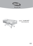
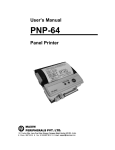
Atari 1027 Printer
Field Service Manual
5-i
ATARI
1027 PRINTER
FIELD SERVICE MANUAL
TM
Atari 1027 Printer
Field Service Manual
ii
Atari believes that the information described in this manual
is accurate and reliable, and much care has been taken in its
preparation. However, no responsibility, financial or
otherwise, shall be accepted for any consequences arising out
of the use of this material. Information contained herein is
subject to change. Revisions may be issued to advise of such
changes and/or additions.
Correspondence regarding this document should be forwarded to
Director of Technical Support, Consumer Product Service,
Atari, Incorporated, 845 W. Maude Avenue, Sunnyvale, CA 94086.
Atari 1027 Printer
Field Service Manual
iii
TABLE OF CONTENTS
Section
Title
Page
INTRODUCTION
v
THEORY OF OPERATION
Overview
User Interface
Mechanical
Case
Type Selection
Type Wheel Movement
Hammer Movement
Hammer Strike
Paper Feed
Character Sensing
Type Wheel Home Position Sensing
Hammer Home Position Sensing
Ink Roll Mechanism
Manual Knob and Paper Lock/
Release Lever
Electronic
Power Supply Circuit
Microprocessor 8049 (MPU)
Interface Circuits
Wheel, Hammer Motor Drive Circuit
Hammer Select Solenoid Drive Circuit
Character Select Solenoid Drive Circuit
DC Motor Drive Circuit
Sensor Signal Circuit
Power-on Reset Circuit
Oscillator Circuit
1-1
1-1
1-3
1-4
1-4
1-7
1-7
1-7
1-7
1-7
1-7
1-7
1-8
1-8
TESTING
Equipment Required
Diagnostic Procedure
Setting up the 1027 for testing and
using CPS Diagnostic Diskette with
the file T1027.BAS
Test for Character Skew
2-1
2-1
2-1
DISASSEMBLY/ASSEMBLY
3-1
SYMPTOM CHECKLIST
4-1
DRAWINGS AND PARTS LIST
5-1
SERVICE BULLETINS
6-1
1
1-8
1-8
1-8
1-9
1-9
1-9
1-9
1-10
1-10
1-10
1-10
1-10
2
2-1
2-5
3
4
5
6
Atari 1027 Printer
Field Service Manual
iv
LIST OF ILLUSTRATIONS
Figure
1-1
1-2
1-3
1-4
1-5
1-6
2-1
2-2
2-3
2-4
2-5
2-6
5-1
5-2
5-3
5-4
Title
1027 Printer Block Diagram
1027 Printer Controls/Indicators
1027 Printer Back View
1027 Printer Final Assembly
1027 Printer Mechanical Assembly
Power Supply Circuit
All Function Test Printout
Standard Character Set
International Character Set
Standard Character Set With Underline
Direction Print Check
Character Skew Printout
1027 Printer Schematic
1027 Printer Silkscreen
1027 Printer Final Assembly
1027 Printer Mechanical Assembly
Page
1-2
1-3
1-4
1-5
1-6
1-9
2-3
2-3
2-4
2-4
2-4
2-6
5-3
5-5
5-7
5-9
LIST OF TABLES
Table
4-1
4-2
Title
Page
Symptom Checklist
Diagnostic Table
Atari 1027 Printer
Field Service Manual
4-1
4-3
v
INTRODUCTION
The Atari 1027TM Printer Field Service Manual is a reference
guide for the service technician. The information presented in
this manual, when used in conjunction with Atari training,
enables you to repair and maintain the 1027 Printer.
This Field Service Manual is organized in six sections:
•
•
•
•
•
•
THEORY OF OPERATION - Overview of how the 1027 Printer
works and what its basic assemblies look like.
TESTING - Review of tests available for diagnosing 1027
Printer problems.
DISASSEMBLY/ASSEMBLY - Procedures for disassembling and
assembling the 1027 Printer.
SYMPTOM CHECKLIST - Failure information to aid in
diagnosing 1027 Printer problems.
DRAWINGS AND PARTS LIST - Silkscreen, schematic, assembly
drawings and a breakdown of parts used to repair the 1027
Printer.
SERVICE BULLETINS - Section to be used to hold Field
Change Orders, Upgrade Bulletins and Tech Tips.
Atari 1027 Printer
Field Service Manual
vi
Atari 1027 Printer
Field Service Manual
vii
SECTION 1
THEORY OF OPERATION
OVERVIEW
The ATARI 1027TM Printer is a letter quality impact printer
that averages 10 characters per second. It is a hard copy
output peripheral intended for use under the control of the
ATARI 400TM, 800TM, 600XLTM, 800XLTM or 1200XLTM computers. It
connects directly to the SIO peripheral port of the computer
(no interface is required). The printer mechanism is a type
wheel assembly. All firmware is resident in the printer and
executed by an onboard microprocessor which controls the
functions of the printer.
Figure 1-1 on next page show a block diagram of the functional
flow of the 1027.
Atari 1027 Printer
Field Service Manual
4-1
DATA IN
BUFFER
DATA OUT
BUFFER
COMMAND
BUFFER
5V/READY
BUFFER
Transistor
Array
MPU
8049
5V
Wheel
Stepping Motor
Wheel
Stepping Motor
Character Select
Solenoid Driver
Character Select
Solenoid
Hammer Select
Solenoid Driver
Hammer Select
Solenoid Driver
DC Motor Driver
DC Motor
Hammer Home Position
Sensor Circuit
Hammer Home
Position Sensor
Wheel Home Position
Sensor Circuit
Wheel Home
Position Sensor
Wheel Timing
Signal Circuit
Wheel Timing
Zero Timing
Signal Circuit
Zero Timing
6V
Voltage
Regulator
AC
Adaptor
Figure 1-1. 1027 Printer Block Diagram
Atari 1027 Printer
Field Service Manual
4-2
USER INTERFACE
Figure 1-2 shows the location of the Controls/Indicators.
Figure 1-2. 1027 Printer Controls/Indicators
The Controls/Indicators and their functions are:
Access Door - Allows access to the plastic gears for
lubrication.
Paper Lock/Release Lever - When this lever is moved back
(direction of arrow) the paper chute opens to
allow insertion of paper. When this lever is
moved forward, there is pressure against the
platen and paper is fed.
POWER - The microprocessor is reset when the POWER button is
pressed.
Power-on Light - The LED indicates that power to the unit is
ON.
Manual Knob - Turn the manual knob to move and position the
paper in the printer.
Atari 1027 Printer
Field Service Manual
4-3
The back panel contains the Power Input Jack and two
Input/Output (I/O) connectors (See Figure 1-3).
Figure 1-3. 1027 Printer Back View
Mechanical
This section describes the mechanical characteristics of the
1027 Printer. For an overall understanding of the 1027
printer. operation, read both this section and the Electronic
Section which follows the mechanical. Use Figure 1-4 and
Figure 1-5 as reference for the following discussion.
Case
The outer case is composed of four pieces of plastic. The
pieces are: 1) the upper case; 2) the lower case; 3) the
bezel; and, 4) the cover.
Atari 1027 Printer
Field Service Manual
4-4
Figure 1-4. 1027 Printer Final Assembly
Atari 1027 Printer
Field Service Manual
4-5
Figure 1-5. 1027 Printer Mechanical Assembly
Atari 1027 Printer
Field Service Manual
4-6
**MECHANICAL REFERENCES MADE HERE ARE FOR ELECTRONIC VERIFICATION ONLY.**
Type Selection
The DC motor drives the main gear (on the spring clutch
assembly) via the idle gear to rotate the type wheel shaft and
the type wheel assembly. When the desired type comes into
position facing the hammer, Solenoid A is turned on and the
type wheel select lever stops the type wheel shaft.
Type Wheel Movement
The wheel select pulse motor assembly is linked to the type
wheel assembly by a wire via the wheel select pulley assembly
to move the wheel back and forth along the type wheel shaft.
Hammer Movement
The hammer pulse motor assembly is linked to the hammer
assembly by a wire via the hammer move pulley assembly to move
the hammer assembly back and forth along the hammer shaft.
Hammer Strike
The DC motor rotates the type wheel shaft via the idle gear
which rotates the cam attached to the type wheel shaft, hammer
lever (A) and hammer lever (B) to strike the hammer.
Paper Feed
The DC motor rotates the type wheel shaft via the idle gear,
which rotates the cam attached to the type wheel shaft, the
paper feed lever and the rubber roller linked to the lever to
feed paper.
Paper is fed only when the concave part of the timing cam and
the convex part of the paper feed lever face each other (blank
type is selected).
Character Sensing
The type and the reference postion of each type are detected
by the photosensor (sensor (A) unit)* through the sensor plate
assembly mounted on the same shaft as the type wheel.
Type Wheel Home Position Sensing
The home position of the type wheel is detected by the
photosensor (sensor (A) unit)* through the sensor plate
assembly mounted on the type wheel.
*Sensor (A) contains more than one photosensor.
Atari 1027 Printer
Field Service Manual
4-7
Hammer Home Position Sensing
The home position of the hammer assembly is detected by the
photosensor as the shutter plate mounted on the hammer
assembly moves into and out of the sensor.
Ink Roll Mechanism
The ink roll manually snaps onto the plastic post in front of
and parallel to the type wheel.
Manual Knob and Paper Lock/Release Lever
When the manual knob is pushed in and turned clockwise it
rotates the rubber roller (which is gear-linked to the manual
knob) to feed paper forward. Counter-clockwise rotation feeds
the paper in the reverse direction.
When the paper lock/release lever is moved back (direction of
arrow), the paper chute opens to allow insertion of paper.
When this lever is moved forward, the friction roller presses
against the platen and paper is fed.
ELECTRONIC
The 1027 Printer electronics consists of 10 elements which are
discussed in the following paragraphs:
•
•
•
•
•
•
•
•
•
•
the
the
the
the
the
the
the
the
the
the
Power Supply Circuit
Microprocessor 8049 (MPU)
Interface Circuits
Wheel, Hammer Motor Drive Circuit
Hammer Select Solenoid Drive Circuit
Character Select Solenoid Drive Circuit
DC Motor Drive Circuit
Sensor Signal Circuit
Power ON Reset Circuit
Oscillator Circuit
Power Supply Circuit
The main power supply is an external AC Adaptor rated at 9.5V
@ 40VA. Regulated outputs are obtained through a 3-terminal
regulator in the main unit.
The power supply system consists of:
Vc 5V ± 5% for the logic circuit and for the sensor circuit.
Vp 6V ± 10% for driving the pulse motors, DC motor and
solenoids
Atari 1027 Printer
Field Service Manual
4-8
Figure 1-6. Power Supply Circuit
Microprocessor 8049 (MPU)
The MPU is an N-MOS custom microprocessor with a built-in 2K
ROM, a 128-byte RAM and a clock circuit. Most of the IC pits
are used as I/O ports.
Interface Circuits
The unit uses a serial interface. The serial port consists of
a serial DATA OUT (transmission) line, a serial DATA IN
(receiver) line and other miscellaneous control lines.
Wheel, Hammer Motor Drive Circuit
The transistor array LB1259 has active high inputs in the
equivalent circuit. The wheel select pulse motor and the
hammer pulse motor are stepper motors driven by 2-phase
excitation. Clock pulses to the motor are approximately 5
msec.
Hammer Select Solenoid Drive Circuit
Solenoid B, the hammer select solenoid, is controlled by a
single pulse input of approximately 10 msec from P21 (pin 22)
of the MPU.
Atari 1027 Printer
Field Service Manual
4-9
Character Select Solenoid Drive Circuit
Solenoid A, the character select solenoid, is controlled by a
single pulse input of approximately 8 msec. from P20 (pin 21)
of the MPU.
The character select signal goes High at the rising edge of
wheel timing and goes Low after approximately 3 msec of the
next rising edge of wheel timing.
DC Motor Drive Circuit
While the signal is Low at P22 (pin 23) of the MPU, the DC
motor keeps rotating. Sensor Signal Circuit
The sensor of this circuit consists of a photo diode and a
photo transistor. The circuit composed of the buffer and two
resistors (IOK, 22K) is a Schmitt trigger circuit.
Power ON Reset Circuit
When the printer power switch is turned on, the MPU is reset
by the power ON reset circuit. At power ON, the capacitor is
charged to give a Low steal to the MPU RST (pin 4) terminal
for a moment. After approximately 100msec. the RST terminal
goes High.
Oscillator Circuit
The MPU uses an external quartz oscillator which determines
the operation frequency.
The oscillation frequency is 6 MHz ± 0.3%.
Atari 1027 Printer
Field Service Manual
4-10
SECTION 2
TESTING
Equipment Required
•
•
•
•
•
•
•
•
An Atari Computer and accessories
A BASIC language cartridge
An Atari Disk Drive
CPS Diagnostic Diskette with the file T1027.BAS (P/N
FD100577, Rev. 02)
A 15 MHz oscilloscope
A Digital Voltmeter
A precision screwdriver kit
A Soldering Iron
Diagnostic Procedure
The testing procedures available for the 1027 are:
•
•
CPS Diagnostic Diskette with the file T1027.BAS.
A test for character skew which consists of a BASIC
Program which you will type in.
CAUTIONS: USE ONLY GOOD QUALITY 81/2 X 11 STANDARD UNLINED
PAPER. DO NOT USE ROLL PAPER.
DO NOT USE LABELS OR ANY ADHESIVE - BACKED MATERIAL. NEVER
PRINT WITHOUT PAPER IN THE PRINTER.
The following pages explain how to set up the 1027 for testing
and contain procedures and sample printouts for each test.
Setting up the 1027 for testing and using CPS Diagnostic
Diskette with the file T1027.BAS.
1. Connect the computer to the TV set as shown in the
computer owner's manual.
2. Plug the 1027 into the power adaptor.
3. Plug an I/O cable into the computer and the 1027.
4. Connect the disk drive to the computer as shown in the
owner's manual.
5. Power up the 1027 Printer. Wait for the printer to
complete its initialization. During initialization the
Type Wheel Assembly moves to the left end of the
carriage, the Type Wheel Assembly rotates, then moves a
short distance to the right and stops.
6. Power up the disk drive. Wait for the disk drive to
complete its initialization.
7. Insert the CPS Diagnostic Diskette with the file
T1027.BAS into the disk drive and close the door.
Atari 1027 Printer
Field Service Manual
5-1
8. Insert the BASIC cartridge into the computer (if
applicable).
NOTE: This program requires the use of BASIC to execute. Later
model computers may have BASIC already installed.
9.Turn on the computer and TV set. Wait for the computer to
complete its initialization. TV display should exhibit
"READY" in white letters on a blue background.
10.Enter the command RUN "D1:Tl027.BAS" and terminate with
the RETURN key.
11.The program will now load and execute. 12. The following
menu appears:
TEST FACILITY
FOR THE
1027 PRINTER
REV. 2
1)
2)
3)
4)
5)
6)
7)
8)
ALL FUNCTION TEST
STANDARD CHAR SET
INTERNATIONAL CHAR SET
UNDERLINE CHECK
DIRECTION PRINT CHECK
CARRIAGE RETURN LOOP
HORIZONTAL STEP MOTOR LOOP
SELECTIVE CHAR PRINT LOOP
Q) STOP TEST AND RETURN TO MENU
PLEASE SELECT AN OPTION
Select 1) for the printout illustrated in Figure 2-1. This
test runs continuously until Q is pressed to stop the test and
return to the menu.
Atari 1027 Printer
Field Service Manual
4-2
1027 PRINTER FUNCTION TEST, PASS # 1
STANDARD CHAR SET
!”#$%&’()*+-0123456789:;,=.?@ABCDEFGHIJKLMNOPQRSTUVWXYZ[\]^_'abcdefghijklmno
pqrstuvwxyz
INTERNATIONAL CHAR SET
áùÑÉçôí₤ïüäÖúÜâûîéèñêåàÅ↑↓←→ ! ”#$%&’()*+-0123456789:;,=.?@ABCDEFGHIJKLMNOPQR
STUVWXYZ[\]^_'abcdefghijklmnopqrstuvwxyzÄ
STANDARD CHAR SET WITH UNDER-LINE
!”#$%&’()*+-0123456789:;,=.?@ABCDEFGHIJKLMNOPQRSTUVWXYZ[\]^_'abcdefghijklmno
pqrstuvwxyz
DIRECTION PRINT CHECK
00000000011111111112222222222333333333344444444445555555555666666666677777777778
12345678901234567890123456789012345678901234567890123456789012345678901234567890
END OF TEST
Figure 2-1. All Function Test Printout
Select 2) to print the standard character set. This option
prints the standard character set except for CONTROL N and
CONTROL O. This test runs continuously until Q is pressed to
stop the test and return to the menu. Figure 2-2 illustrates
the standard character set.
STANDARD CHAR SET
!”#$%&’()*+-0123456789:;,=.?@ABCDEFGHIJKLMNOPQRSTUVWXYZ[\]^_'abcdefghijklmno
pqrstuvwxyz
Figure 2-2. Standard Character Set
Select 3) to print the International character set. This
option prints the International character set except for
CONTROL N and CONTROL O. This test runs continuously until Q
is pressed to stop the test and return to the menu. Figure 2-3
illustrates the International character set.
INTERNATIONAL CHAR SET
áùÑÉçôí₤ïüäÖúÜâûîéèñêåàÅ↑↓←→ ! ”#$%&’()*+-0123456789:;,=.?@ABCDEFGHIJKLMNOPQR
STUVWXYZ[\]^_'abcdefghijklmnopqrstuvwxyzÄ
Figure 2-3. International Character Set
Atari 1027 Printer
Field Service Manual
4-3
Select 4) to print the standard character set with underline.
This option prints the standard character set except for
CONTROL N and CONTROL O. After each character is printed, it
is underlined before the next character is printed. This test
runs continuously until Q is pressed to stop the test and
return to the menu. Figure 2-4 illustrates the standard
character set with underline.
STANDARD CHAR SET WITH UNDER-LINE
!”#$%&’()*+-0123456789:;,=.?@ABCDEFGHIJKLMNOPQRSTUVWXYZ[\]^_'abcdefghijklmno
pqrstuvwxyz
Figure 2-4. Standard Character Set With Underline
Select 5) for the Direction Print Check. This checks the
ability of the Operating System to determine when the print
buffer is full and to print the full length of the page in
both directions. This test runs continuously until Q is
pressed to stop the test and return to the menu. Figure 2-5
illustrates the Direction Print Check.
DIRECTION PRINT CHECK
00000000011111111112222222222333333333344444444445555555555666666666677777777778
12345678901234567890123456789012345678901234567890123456789012345678901234567890
Figure 2-5. Direction Print Check
Select 6) to perform continuous carriage returns. This allows
for scoping the carriage return logic, the wheel select pulse
motor and the hammer pulse motor. Press Q to stop this test
and return to the menu.
Select 7) to move the print head right then left continuously.
This allows for the scoping . of the wheel select pulse motor.
Press Q to stop this test and return to the menu.
Atari 1027 Printer 2-4 Field Service Manual
Select 8) to continuously print any selected character for as
many lines as desired. This test runs continuously until Q is
pressed TWICE to stop the test and return to the menu.
Atari 1027 Printer
Field Service Manual
4-4
Note: The test will continue printing the letter Q unless Q is
pressed TWICE.
CAUTION: Never print without paper as it may damage the type
wheel and cause the next several sheets of paper to smear.
Test for Character Skew
Enter the following. Remember to press RETURN at the end of
each line.
10
20
30
40
50
55
60
70
90
OPEN #1,8,0,"P:"
FOR X=1 TO 30
FOR Y=1 TO 70
? #1;"E";
NEXT Y
?#1; CHR$ (127)
NEXT X
CLOSE #1 80 STOP
GOTO 10
Insert a fresh, clean sheet of paper.
Type RUN and press RETURN.
The program will print 30 lines of the letter E. When the
printout has finished, use a ruler to draw a number of
vertical lines (See Figure 2-6) between the columns of letter
E's. Check that the letters within each vertical column are
aligned directly under each other. If they are not aligned
correctly, the mechanism needs to be swapped. If the letters
are the same as or are further off center than shown in Figure
2-6, type CONT and RETURN. The test will repeat. Carefully
draw the vertical lines again. If the letters are still not
correctly aligned, swap the mechanism. Include the test
printout with the returned mechanism.
Figure 2-6 shows a printout of this test which indicates that
the mechanism needs to be swapped.
Atari 1027 Printer
Field Service Manual
4-5
Figure 2-6. Character Skew Printout.
(with vertical lines drawn)
Atari 1027 Printer
Field Service Manual
4-6
SECTION 3
DISASSEMBLY/ASSEMBLY
Equipment Required:
•
A precision screwdriver set
Preventive Maintenance
Each Atari 1027 Printer which is disassembled must have the
following Preventive Maintenance performed:
•
•
Carefully clean any dust or dirt from inside the unit use a dry, soft cloth.
Use alcohol or benzene to remove any stains. DO NOT USE
thinner, trichloroethylene or ketone solvents - they may
damage the plastic parts.
CAUTIONS: NEVER OIL OR CLEAN THE TYPE WHEEL ASSEMBLY. IT IS
MADE OF RUBBER AND MAY BE DAMAGED.
DO NOT TOUCH THE TYPE WHEEL SHAFT - ACID FROM YOUR HANDS CAN
CAUSE OXIDATION.
DO NOT USE ROLL PAPER. USE ONLY GOOD QUALITY 8 1/2 BY 11
STANDARD UNLINED PAPER. INTONE SHEET AT A TIME. ANY OTHER SIZE
OR TYPE OF PAPER MAY RESULT. IN THE PRINTER JAMMING AND DAMAGE
TO THE TYPE WHEEL ASSEMBLY.
DO NOT USE LABELS OR ANY ADHESIVE - BACKED MATERIAL.
Atari 1027 Printer
Field Service Manual
5-1
Use Figure 5-3 (Page 5-7) and Figure 5-4 (Page 5-9) as
reference for this section.
Disassembly
•
Remove the cover.
•
Turn the unit upside down and remove the four screws
holding the lower case in place.
•
Remove the three screws holding the bezel to the lower
case. Remove the screw located between the Input/Output
(I/O) ports. Turn the unit over.
•
Remove the bezel and lower case.
•
Remove the four screws holding the printer mechanism to
the bottom cover.
•
Lift up the printer mechanism and unplug connectors 1,2,
and 3 from the PC Board.
•
If necessary, lift off the RF Shield Top.
Assembly
•
Plug connectors 1, 2 and 3 into the PC Board.
•
Replace RF shield top if it has been removed.
•
Set the printer mechanism in the lower case, positioning
it over the four lower case screw holes.
•
Insert and tighten the four lower case screws.
•
Fit the upper case on the lower case.
•
Slide the bezel onto the front of the unit - align the
LED with the opening in the bezel; slide the three tabs
into the lower case; hook the top tabs into the upper
case.
•
Carefully turn the unit over while holding the two cases
and bezel together.
•
Insert and tighten the four screws holding the lower case
in place.
•
Insert and tighten the three screws holding the bezel to
the lower case.
•
Insert and tighten the screw located between the
Input/Output (I/O) ports.
•
Replace the cover.
Atari 1027 Printer
Field Service Manual
4-2
SECTION 4
TABLE 4-1
SYMPTOM CHECKLIST
Symptom
Possible Cause
DOES NOT PRINT CHARACTERS
Repair Method
Hammer Pulse Motor
Assembly, Wheel Select
Pulse Motor Assembly,
DC Motor and Solenoid
Assembly operate
normally but no
printing is done.
Ink Roll is not mounted
properly, ink is
exhausted.
Mount Ink Roll properly
or replace the Ink
Roll.
Hammer Pulse Motor
Assembly does not move
properly.
Foreign matter has
accumulated between
gears.
Rotate the pulley gear
by hand and remove
foreign matter.
Hammer Pulse Motor
Assembly lead wire is
cut.
Repair, if possible. Is
there current to each
phase of the motor (See
Pg 4-3)? If yes,
replace printer
mechanism. If none,
troubleshoot and
repair.
Wheel Select Pulse
Motor Assembly does not
move
Wheel Select Pulse
Motor Assembly lead
wire is cut.
Repair if possible. Is
there current to each
phase of properly. the
motor (See Pg 4-3)?
If yes, replace printer
mechanism. If none,
troubleshoot, and
repair.
DC motor does not
rotate.
Foreign matter has
accumulated between
gears.
Rotate the pulley gear
by hand and remove
foreign matter.
DC Motor Lead wire is
cut.
Repair if possible. Is
there current to the
motor(See Pg 4-3)? If
yes, replace printer
mechanism. If none,
troubleshoot and
repair.
Solenoid lead wire is
cut.
Repair if possible. Is
there current to the
Solenoid (See Pg 4-3)?
If yes, replace printer
mechanism. If
none, troubleshoot and
repair.
Atari 1027 Printer
Field Service Manual
5-1
SYMPTOM CHECKLIST (continued)
Symptom
Possible Cause
DOES NOT PRINT CHARACTERS
At Power-on Reset,
Hammer Assembly does
not come to the initial
position (See Page 2-1).
At Power-on Reset, Type
Wheel Assembly does not
come to the initial
position (See Page 2-1).
At Power-On Reset, Type
Wheel Unit keeps
rotating.
Hammer Move Sensor Unit
does not work.
At Power-on Reset, Type
Wheel Assembly does not
rotate enough.
Sensor (A) Unit does
not work.
Printer operates
normally with no
misprinting.
Paper Lock/Release
Lever is set for
release position.
The preceding character
on the same character
ring is printed.
The electrolytic
capacitor lead wire of
the DC motor is
disconnected from the
motor terminal.
Sensor (A) Unit does
not work.
Sensor (A) Unit does
not work.
Repair Method
Verify there is a
signal at LSI Pin 35.
If none, troubleshoot
and repair.
Verify there is a
signal at LSI Pin 36.
If none, troubleshoot
and repair.
Verify there is a
signal at LSI Pin 39.
If none, troubleshoot
and repair.
Verify there is a
signal at LSI Pin 1. If
none, troubleshoot and
repair.
PAPER DOES NOT FEED
Check the position of
Paper Lock/Release
Lever.
MISPRINTING
Atari 1027 Printer
Field Service Manual
5-2
Solder the lead wire.
TABLE 4-2
DIAGNOSTIC TABLE
Diagnostic
Option to
Activate Signal
Printer Mechanism
WA
WB
WC
WD
(Wheel
(Wheel
(Wheel
(Wheel
Select
Select
Select
Select
Lead)
Lead)
Lead)
Lead)
P
U
L
S
E
Where to Look For
Signals
Use Option #7
Connector 1 Pins 9,10,11
and 12
Use Option #6
Connector 1 Pins 3,4,5,6
MT (DC Motor)
Use Option #8
Connector 2 Pin 2
HS (Hammer Select Solenoid)
Solenoid B
Use Option #5
Connector 2 Pin 4
CS (Char. Select Solenoid)
Solenoid A
Use Option #5
Connector 2 Pin 6
WT (Wheel Timing)
Use Option #8
Connector 2 Pin 4
ZT (Zero Timing Sensor)
Use Options #1, #2
and #3
Connector 2 Pin 2
HHP (Hammer Home Position)
Use Option #6
Connector 2 Pin 9
WHP (Wheel Home Position
Use Option #6
Connector 2 Pin 6
HA
HB
WC
WD
(Wheel
(Wheel
(Wheel
(Wheel
Select
Select
Select
Select
Lead)
Lead)
Lead)
Lead)
M
T
R
1
P
U
L
S
E
M
T
R
2
Atari 1027 Printer
Field Service Manual
5-3
SECTION 5
DRAWINGS AND PARTS LIST
Attached to the front cover are representative silkscreens and
schematics for the 1027 Printer. Remove them and place them in
this section. Minor variations in design may be encountered
depending on the production date of the unit, but these
schematics provide all details required for an in-depth
understanding of all 1027 Printer units.
Atari 1027 Printer
Field Service Manual
5-4
Figure 5-1. 1027 Printer Schematic
Atari 1027 Printer
Field Service Manual
5-5
Figure 5-2. Printer Silkscreen
Atari 1027 Printer
Field Service Manual
5-6
Figure 5-3 1027 Printer Final Assembly
Atari 1027 Printer
Field Service Manual
5-7
This page intentionally left blank.
Atari 1027 Printer
Field Service Manual
5-8
Figure 5-4. 1027 Printer Mechanical Assembly
This page intentionally left blank.
Atari 1027 Printer
Field Service Manual
5-9
SECTION 6
SERVICE BULLETINS
This section is to be used by you to file the three
classifications of service bulletins that are periodically
released by the Director of Technical Support.
The following are brief descriptions of each classification:
FIELD CHANGE ORDER
A Field Change Order describes mandatory hardware or software
changes to ATARI products and instructs how to implement these
changes. The changes must be performed on all units serviced
or repaired.
UPGRADE BULLETIN
An Upgrade Bulletin describes product improvements or
modifications that the consumer may wish to purchase. These
bulletins allow you to modify the customer's unit to add
capabilities which may not have been available when the unit
was originally manufactured.
TECH TIP
A Tech Tip is a document of a general nature which transmits
routine service or repair information. By communicating
methods developed since you attended training classes, Tech
Tips aid to continuously improve repair skills and increase
knowledge of ATARI products.
Other times, Tech Tips alert you to units that have been
modified and are now standard for ATARI Manufacturing, but are
different from many existing units and require different
repair techniques.
Atari 1027 Printer
Field Service Manual
5-10