1
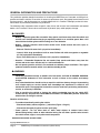
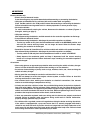
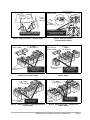
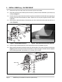
BREEZeasy Kit
Installation
Instructions
Gasoline and Electric
Vehicles:
• Precedent
• DS Golf Car
Publication
AM1218301
These instructions apply to the following kits:
AM1217301
AM1217501
Edition Code
0506A00000
AM1217901
AM1218001
GENERAL INFORMATION AND PRECAUTIONS
This publication provides detailed instructions for installing the BREEZeasy on Precedent and DS golf car
gasoline and electric vehicles. Ensure that all necessary replacement parts, the appropriate maintenance and
service manual(s), and this document are available before this kit is installed. Thoroughly review this document before any installation procedures are performed.
The following safety statements relate to specific safety issues and must be read, understood, and heeded
before a kit is installed. Failure to do so could result in personal injury and/or property damage.
ý DANGER
• Battery – Explosive gases! Do not smoke. Keep sparks and flames away from the vehicle and
service area. Ventilate when charging or operating vehicle in an enclosed space. Wear a full
face shield and rubber gloves when working on or near batteries.
• Battery – Poison! Contains acid! Causes severe burns. Avoid contact with skin, eyes, or
clothing. Antidotes:
- External: Flush with water. Call a physician immediately.
- Internal: Drink large quantities of milk or water. Follow with milk of magnesia or vegetable
oil. Call a physician immediately.
- Eyes: Flush with water for 15 minutes. Call a physician immediately.
• Gasoline – Flammable! Explosive! Do not smoke. Keep sparks and flames away from the
vehicle and service area. Service only in a well-ventilated area.
• Do not operate gasoline vehicle in an enclosed area without proper ventilation. The engine
produces carbon monoxide, which is an odorless, deadly poison.
ý WARNING
• Follow the procedures exactly as stated in this instruction, and heed all DANGER, WARNING,
and CAUTION statements in this instruction as well as those on the vehicle and battery
charger.
• Only trained technicians should service or repair the vehicle or battery charger. Anyone doing
even simple repairs or service should have knowledge and experience in electrical and
mechanical repair. The appropriate instructions must be used when performing maintenance,
service, or accessory installation.
• Prior to servicing the vehicle or leaving the vehicle unattended, turn the key switch OFF,
remove the key, and place the Forward/Reverse handle in the NEUTRAL position. Chock the
wheels when servicing the vehicle.
Gasoline vehicles only:
• To avoid unintentionally starting the vehicle:
- Disconnect battery cables, negative (–) cable first (Figure 1, Page 5).
- Disconnect the spark plug wire from the spark plug.
• Frame ground – Do not allow tools or other metal objects to contact frame when
disconnecting battery cables or other electrical wiring. Do not allow a positive wire to touch
the vehicle frame, engine, or any other metal component.
WARNING CONTINUED ON NEXT PAGE...
Copyright © 2006 Club Car, Inc.
Page 2
BREEZeasy Kit Installation Instructions (AM1218301)
ý WARNING
Electric vehicles only:
• Electric Carryall Industrial trucks:
Press the emergency stop switch down before disconnecting or connecting the batteries.
• IQ System and PowerDrive Plus vehicles (with serial number 9801 and greater):
Place Tow/Run switch in the TOW position before disconnecting or connecting the batteries.
Failure to heed this warning could result in a battery explosion or severe personal injury.
• All electric vehicles:
To avoid unintentionally starting the vehicle, disconnect the batteries as shown (Figures 2
through 6, starting on page 5).
• IQ System vehicles:
After disconnecting the batteries, wait 90 seconds for the controller capacitors to discharge.
• Carryall Electric Industrial trucks:
After disconnecting the batteries, discharge the controller capacitors as follows:
- Turn the key switch to ON, place the Forward/Reverse handle in the REVERSE position, and
wait until the reverse warning buzzer can no longer be heard. When the buzzer stops
sounding, the controller is discharged.
• PowerDrive System 48, PowerDrive Plus vehicles, and 36-volt vehicles with speed controllers:
After disconnecting the batteries, discharge the controller capacitors as follows:
- Turn key switch to ON and place the Forward/Reverse handle or switch in REVERSE.
- Slowly depress the accelerator pedal and keep it depressed until the reverse warning
buzzer can no longer be heard. When the buzzer stops sounding, the controller capacitors
are discharged.
All vehicles:
• Wear safety glasses or approved eye protection when servicing the vehicle or battery charger.
Wear a full face shield and rubber gloves when working on or near batteries.
• Do not wear loose clothing or jewelry such as rings, watches, chains, etc., when servicing the
vehicle or battery charger.
• Moving parts! Do not attempt to service the vehicle while it is running.
• Hot! Do not attempt to service hot engine, exhaust system, or motor. Failure to heed this
warning could result in severe burns.
• Use insulated tools when working near batteries or electrical connections. Use extreme
caution to avoid shorting of components or wiring.
• Lift only one end of the vehicle at a time. Use a suitable lifting device (chain hoist or hydraulic
floor jack) with 1000 lb. (454 kg) minimum lifting capacity. Do not use lifting device to hold
vehicle in raised position. Use approved jack stands of proper weight capacity to support the
vehicle and chock the wheels that remain on the floor. When not performing a test or service
procedure that requires movement of the wheels, lock the brakes.
• If wires are removed or replaced, make sure wiring and wire harness are properly routed and
secured. Failure to properly route and secure wiring could result in vehicle malfunction,
property damage, personal injury, or death.
• For vehicles with cargo beds, remove all cargo before raising the bed or servicing the vehicle.
If the vehicle is equipped with a prop rod, ensure that it is securely engaged while bed is
raised. Do not close bed until all persons are clear of cargo bed area. Keep hands clear of all
crush areas. Do not drop cargo bed; lower gently and keep entire body clear. Failure to heed
this warning could result in severe personal injury or death.
BREEZeasy Kit Installation Instructions (AM1218301)
Page 3
TOOLS REQUIRED
3/16-INCH DRILL BIT
7/16-INCH WRENCH
9/16-INCH WRENCH
ELECTRICAL
TAPE
ELECTRIC
HAND DRILL
TORX-HEAD
SCREWDRIVER
PARTS IN THIS KIT
BLOWER
AM1217201 (12V)
AM1217401 (24V)
QTY-1
PLASTIC BRACKET
QTY-2
PRECEDENT BRACKET SET
AM1217601
LOUVER
AM1217701
QTY-2
POINTER KNOB
AM1218201
QTY-1
DS BRACKET SET
AM1217601
NYLON BOLT
QTY-4
ALUMINUM BRACKET
QTY-2
UPPER ALUMINUM BRACKET
QTY-2
WASHER
QTY-2
LOWER ALUMINUM BRACKET
QTY-2
1.
NUT
QTY-4
1-1/4-INCH
NYLON BOLT
QTY-2
3/4-INCH
NYLON BOLT
QTY-2
WASHER
QTY-2
NUT
QTY-4
DISCONNECT THE BATTERY CABLES
1.1.
Disconnect the battery cables as instructed. See WARNING "To avoid unintentionally starting..."
on page 2.
1.2.
Gasoline vehicles: Disconnect the spark plug wire from the spark plug.
Page 4
BREEZeasy Kit Installation Instructions (AM1218301)
Remove negative (–)
cable first.
Place Tow/Run
switch in TOW.
Remove
negative (–
cable first.
CCI 102519501
TOW
RUN
4
RUN
CCI 102519501
Place TOW/RUN Switch in the TOW
position before disconnecting or
connecting battery cables.
DISCONNECT BATTERY CABLES
BEFORE WORKING ON VEHICLE
Figure 1 Battery Disconnect – Gasoline Vehicle
Place Tow/Run
Switch in TOW.
FRONT
OF VEHICLE
2
FRONT
OF VEHICLE
RUN
TOW
IN
RN
WA
1
Figure 2 Battery Disconnect –
Precedent Electric Vehicle
Place Tow/Run
Switch in TOW.
RUN
3
TOW
FRONT
OF VEHICLE
3
TOW
2
G
RN
WA
ING
5
1
5
2
1
3
4
4
6
6
Remove negative
cable first.
Place Tow/Run switch in
the TOW position before
disconnecting or connecting
battery cables.
Figure 3 Battery Disconnect – IQ System and
PowerDrive Plus Electric Vehicle
Remove negative
cable first.
Place Tow/Run switch in
the TOW position before
disconnecting or connecting
battery cables.
Figure 4 Battery Disconnect – PowerDrive Plus
Electric Vehicle
1
2
FRONT
OF VEHICLE 3
FRONT
OF VEHICLE
2
3
4
6
5
4
1
6
Remove negative
cable first.
Figure 5
Disconnect these
battery cables before
working on vehicle.
Battery Disconnect – PowerDrive System 48
Electric Vehicle
Remove
negative
cable first.
5
Disconnect these
battery cables before
working on vehicle.
Figure 6 Battery Disconnect – V-Glide 36-Volt
Electric Vehicle
BREEZeasy Kit Installation Instructions (AM1218301)
Page 5
2.
INSTALL BREEZeasy ON PRECEDENT
2.1.
Remove the four Torx-head screws that secure the cowl trim to the dash.
2.2.
Align slots and firmly press the black plastic brackets (1) onto each end of the blower (2) until they snap
into place (Figure 7).
2.3.
Partially attach the upper aluminum brackets (3) to the plastic blower brackets with one nylon bolt (4)
and nut at the end nearest the bend as shown. Tighten nuts 1/2 turn past snug only. DO NOT OVERTIGHTEN.
2.4.
With brackets attached to blower, slide the bent part of the aluminum bracket under the cowl trim as
shown (Figure 8).
5
2
1
4
3
Figure 7 Assemble Blower Brackets
Figure 8 Slide Aluminum Bracket Under Cowl Trim
2.5.
Insert the right and left outside Torx screw to hold the fascia trim and blower in place.
2.6.
Before securing the lower aluminum brackets (8), fully thread the Torx screws (9) into the bracket holes
(Figure 9). Secure the lower brackets to the cowl trim. Secure the upper and lower brackets together
with remaining nylon bolts (10), washers (11), and nuts (12) as shown.
COWL TRIM
12
9
8
11
10
Figure 9 Secure Blower to Cowl
Page 6
BREEZeasy Kit Installation Instructions (AM1218301)
2.7.
Thread the power cable under the plastic ribs of the blower as shown(Figure 10).
2.8.
Lift up cowl trim and route cable under trim as shown (Figure 10) and toward passenger side of vehicle.
Figure 10 Route Power Cable
2.9.
Figure 11 Route Power Cable
Lift up floormat and route wire in channel to the battery compartment (Figure 11).
2.10.
Secure power wire to vehicle with wire ties provided.
2.11.
Connect the red wire with in-line fuse and male terminal (12) to the female terminal on the power wire
(13) (Figure 12).
2.12.
Electric vehicle: Attach the red wire to battery no. 1 positive (+) terminal. Attach the black (ground)
wire (14) to battery no. 2 negative (–) terminal (Figure 12).
13
4
3
14
12
1
2
Figure 12 Power Wire Connections - Electric Vehicle
2.13.
Gasoline vehicle: Attach the red wire to the positive (+) battery terminal. Attach the black (ground)
wire to the negative (–) battery terminal.
BREEZeasy Kit Installation Instructions (AM1218301)
Page 7
3.
INSTALL BREEZeasy ON DS
3.1.
Remove screws that secure the key switch housing in place. Tilt housing to access entire bottom edge
of aluminum dash trim (Figure 13).
3.2.
Carefully measure and mark center of dash on aluminum trim.
3.3.
Align slots and firmly press the black plastic brackets (1) onto each end of the blower (2) until they snap
into place (Figure 14).
2
1
Figure 13 Key Switch Housing
Figure 14 Attach Brackets to BlowerS
3.4.
Center blower and mark hole locations (using front slots of plastic brackets) 1/2 inch from edge of
dash.
3.5.
Drill 1/4-inch holes down through aluminum dash trim.
3.6.
Secure aluminum plates (3) to blower with 3/4-inch nylon bolts (4) and nuts (5) by inserting bolts up
through bottom of plates using rear slots as shown (Figure 15).
3.7.
Secure blower to dash by inserting 1-1/4-inch nylon bolts up through dash, aluminum plates, and
blower brackets (Figure 16).
5
4
3
Figure 15 Install Aluminum Plates
3.8.
Page 8
Figure 16 Secure Blower to Cowl
Reattach key switch housing.
BREEZeasy Kit Installation Instructions (AM1218301)
3.9.
Thread the power wire under the plastic ribs of the blower (Figure 17).
Figure 17 Route Power Wire
3.10.
Drill a 3/8-inch hole in the cowl where the power wire comes out of the blower. See following NOTE and
CAUTION.
NOTE: Drill hole as close to fan as possible to limit visibility of hole.
CAUT ION
• Do not damage any components beneath surface of cowl during drilling operation.
3.11.
Insert power wire through hole in cowl and route toward passenger-side of vehicle. Secure power wire
to vehicle with wire ties provided while routing to battery compartment.
3.12.
Connect the red wire with in-line fuse and male terminal (7) to the female terminal on the power wire
(8) (Figure 18).
3.13.
Electric vehicle with six 8-volt batteries: Attach the red wire to battery no. 1 positive (+) terminal.
Attach the black (ground) wire (9) to battery no. 3 negative (–) terminal.
3.14.
Electric vehicle with four 12-volt batteries: Attach the red wire to battery no. 1 positive (+) terminal.
Attach the black (ground) wire (9) to battery no. 2 negative (–) terminal.
9
7
7
P
O
S
2
E
G
Electric vehicle
with four 12-volt
batteries
N
Electric vehicle
with six 8-volt
batteries
8
9
8
E
N
1
G
P
O
E
N
5
P
O
S
E
S
N
P
O
G
G
1
S
3
4
2
FRONT OF
VEHICLE
4
3
6
Figure 18 Power Wire Connections - Electric Vehicle
3.15.
Gasoline vehicle: Attach the red wire to the positive (+) battery terminal. Attach the black (ground)
wire to the negative (–) battery terminal.
BREEZeasy Kit Installation Instructions (AM1218301)
Page 9
4.
CONNECT BATTERY CABLES
ý WARNING
• IQ System and PowerDrive Plus vehicles (with serial number 9801 and greater):
Place Tow/Run switch in the TOW position before disconnecting or connecting the batteries.
Failure to heed this warning could result in a battery explosion or severe personal injury.
• Connect the battery cables, positive (+) cable first. For gasoline vehicles, tighten hardware to 20 ft-lb
(27.1 N·m) (Figure 1). For electric vehicles, tighten hardware to 110 in-lb (12.4 N·m) (Figures 2
through 6, starting on page 5). Coat terminals with Battery Terminal Protector Spray (CCI P/N
1014305) to minimize corrosion.
• Connect the spark plug wire to the spark plug on gasoline vehicles.
QUESTIONS
Questions or comments regarding these kit instructions should be referred to your local Club Car dealer or
distributor. Please know your vehicle model and have these kit instructions available when you call.
Page 10
BREEZeasy Kit Installation Instructions (AM1218301)