1
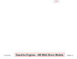
™
GENERAL TWIN SEAL
Operation, Maintenance & Service Manual
SCOPE
Included in the following pages you will find
assembly drawings, exploded views, parts lists,
assembly tips, operational descriptions and
routine maintenance requirements for the current
design of the General Twin Seal™.
TABLE OF CONTENTS
VALVES
Integral Bushing/Retaining Ring Gland ............... 2
Integral Bushing/Bolted Gland ............................ 2
Bushings/One Gland ............................................ 3
Bushings/Two Glands .......................................... 3
Bearings/Dual Retention ..................................... 4
Bearings/Internally & Externally Retained .......... 5
Bearings/Internally Retained w/Two Glands ....... 5
OPERATORS
Model
Model
Model
Model
Model
Model
Model
375 H ........................................................ 6
500 H & 625 H .......................................... 7
376G & 501G ............................................ 8
625G, 751G & 755G ................................ 10
1261G & 1261-7G .................................... 12
1276G ..................................................... 14
1500G ..................................................... 16
BLEEDS
Understanding the DTR Bleed System .............. 18
MISCELLANEOUS
Operation .......................................................... 20
Maintenance ..................................................... 20
Parts .................................................................. 20
Where to find us ................................................ 20
GENERAL VALVE COMPANY
INTEGRAL BUSHING/RETAINING RING GLAND
Typical Arrangement of
6 - GLAND
2"
2"
3"
3"
76 - RETAINING RING
62A - O-RING
62B - O-RING
63 - PACKING
2 - BONNET
49 - GASKET
62C - O-RING
72 - CAP SCREW
C811
C821
CA811
CA821
The smallest of the twin seal valves
do not require discrete bushings due
to minimal hydro seating forces within
the valve. Also note that due to the
size of the operator, the gland is held
in by a retaining ring backed up by
the operator housing.
76B - PIPE PLUG
1 - BODY
5 - SLIP
4 - PLUG
49 - GASKET
62 - O-RING
3 - LOWER PLATE
76A - PIPE PLUG
INTEGRAL BUSHING/BOLTED GLAND
71 - STUD
75 - HEX NUT
72 - CAP SCREW
6 - GLAND (SHOWN 90˚ OUT OF POSITION)
62A - O-RING & 62D BACKUP RING
76 B - PIPE PLUG (SHOWN 90˚ OUT OF POSITION)
62 B - O-RING
63 - PACKING
2 - BONNET
Typical Arrangement of
49 - GASKET
62C - O-RING
1 - BODY
5 - SLIP
4 - PLUG
3 - LOWER PLATE
76A - PIPE PLUG
49 - GASKET
62C - O-RING
GENERAL VALVE COMPANY
2
4"
C811
These units do not require discrete
bushings due to small hydro seating
forces, incorporating a slightly larger
operator however, allows bolted
glands to be employed.
BUSHINGS/ONE GLAND
6˚ SIZE HOLE
LOCATED 90˚ FROM
POSITION SHOWN
76B - PIPE PLUG
(SHOWN OUT OF
POSITION)
Typical Arrangement of
72 - CAP SCREW
1
1 /2"
2"
2"
2"
2"
2"
2"
3"
4"
4"
4"
4"
4"
6"
6"
6"
6"
6"
62A - O-RING
62A - BACKUP RING
6 - GLAND
62B - O-RING
71 - STUD
75 - HEX NUT
2 - BONNET
49 - GASKET
62C - O-RING
63 - PACKING
46 - BUSHING
5 - SLIP
4 - PLUG
1 - BODY
62C - O-RING
49 - GASKET
3 - LOWER PLATE
46 - BUSHING
76A - PIPE PLUG
76B - PIPE PLUG
(16” C811 ONLY)
C921
C841
C851
C861
C911
C921
C941
C911
C821
C841
C911
C921
C941
C411
C421
C821
C841
CA811
6"
6"
6"
8"
8"
8"
8"
8"
8"
8"
10"
10"
10"
10"
10"
10"
12"
12"
C911
C921
C941
C411
C421
C811
C821
C841
C911
C921
C411
C421
CA811
C821
C911
C921
C411
C421
12"
12"
12"
12"
14"
14"
14"
16"
16"
16"
16"
18"
18"
20"
20"
20"
24"
24"
C811
C821
A1911
C921
C811
C821
C911
C411
C811
C821
C921
C411
C811
C411
C421
CA811
C411
C421
71 - STUD
This most popular General Twin Seal design employs
bushings and requires a single gland.
75 - HEX NUT
76A - PIPE PLUG
BUSHINGS/TWO GLANDS
72
6
62B
71
75
-
CAP SCREW
GLAND
O-RING
STUD
NUT
62A
62D
76
63
46
2 - BONNET
49 - GASKET
1 - BODY
46
49
76
71
75
72
-
-
O-RING
BACKUP RING
PIPE PLUG
PACKING
BUSHING
62C
62E
4
5
-
62C 62E 63 62B 23 -62A 62D 6 -
BUSHING
GASKET
PIPE PLUG
STUD
NUT
CAP SCREW
Typical Arrangement of
3"
3"
4"
6"
O-RING
BACKUP RING
PLUG
SLIP
C851
C861
C851
C851
Higher pressure class valves employ
the balanced plug design to minimize
plug hydro forces which in turn
requires two glands.
O-RING
BACKUP RING
PACKING
O-RING
LOWER PLATE
C-PLATE
O-RING
BACKUP RING
GLAND
GENERAL VALVE COMPANY
3
BEARINGS/DUAL RETENTION
71F
75C
62B
63A
76E
76F
76H
76J
76G
71C
75A
95A
2
76A
62E
49C
6B
63B
62F
62G
73
66
62J
62C
76B
71B
75A
62F
62G
76E
76J
76G
76C
-
STUD
NUT
O-RING
PACKING
NEEDLE VALVE
NIPPLE
ELBOW
NIPPLE
BUSHING
STUD
NUT
LIFTING LUG
BONNET
PIPE PLUG
O-RING
GASKET (20” CA911 ONLY)
LANTERN RING
PACKING
O-RING
BACKUP RING
12 PT CAP SCREW
BEARING
O-RING
O-RING
PIPE PLUG
STUD
NUT
O-RING
BACKUP RING
NEEDLE VALVE
NIPPLE
BUSHING
PIPE PLUG
VENT WHILE INJECTING
GREASE
TOP & BOTTOM
3
GREASE AT LEAST
SEMI ANNUALLY
TOP & BOTTOM 3
62A
62D
6A
71G
75C
76D
71A
75A
76A
26C
62J
49A
76C
62H
26B
73
66
5
4
1
62F
62G
46
26B
49B
3
71D
75A
95B
49D
71E
75B
62H
76D
26A
-
O-RING
BACKUP RING
GLAND
STUD
NUT
GREASE INJECTOR
STUD
NUT
PIPE PLUG
BEARING RETAINER
O-RING
GASKET (20” CA911 ONLY)
PIPE PLUG
O-RING
BEARING RETAINER
12 PT CAP SCREW
BEARING
SLIP
PLUG
BODY
O-RING
BACKUP RING
SLIP PAD
BEARING RETAINER
GASKET (20” CA911 ONLY)
LOWER PLATE
STUD
NUT
SUPPORT
GASKET (20” CA911 ONLY)
STUD
NUT
O-RING
GREASE INJECTOR
BEARING RETAINER
Typical Arrangement of
12"
14"
16"
18"
20"
20"
20"
20"
20"
20"
24"
24"
24"
24"
28"
30"
C941
C841
C921
CA821
CA821
CA841
C841
C911
CA911
CA921
CA811
C811
C821
CA821
C811
C821
As valve size increases so
does the plug load,
therefore, these sizes
require bearings.
BEARINGS/DUAL RETENTION
VENT WHILE INJECTING
GREASE
TOP & BOTTOM
3
62B - O-RING
62E - BACKUP RING
63 - PACKING RING
6B - LANTERN RING
76E - NEEDLE VALVE
62A - O-RING
62D - BACKUP RING (2)
Typical Arrangement of
73D - 12 PT CAP SCREW
6A - GLAND
62L - O-RING
73C - 12 PT CAP SCREW
76B - NIPPLE (2)
26B - BEARING RETAINER
76H - ELBOW
76G - BUSHING
76D - GREASE INJECTOR
36"
76C - PIPE PLUG
49C - GASKET
95B - LIFTING LUG
62L - O-RING
71D - STUD
2 - BONNET
49B - GASKET
75 - NUT
76C - PIPE PLUG
62F - O-RING
71A - STUD
62A - O-RING
75 - NUT
62D - BACKUP RING (2)
4 - PLUG
62G - O-RING
66 - BEARING
5 - SLIP
26C - BEARING RETAINER
1 - BODY
76A - PIPE PLUG
26C - RETAINER PLATE
73A - 12 PT CAP SCREW
62A - O-RING
62D - BACKUP RING (2)
46 - SLIP PAD
62K - O-RING
66 - BEARING
62C - O-RING
49A - GASKET
49D - GASKET
76C - PIPE PLUG
62H - O-RING
73B -12 PT CAP SCREW
3 - LOWER PLATE
76E - NEEDLE VALVE
26D - BEARING RETAINER
76F - NIPPLE
76D - GREASE INJECTOR
76G - BUSHING
95A - SUPPORT
71C - STUD
26A - BEARING RETAINER
75 - NUT
71B - STUD
75 - NUT
76A - PIPE PLUG
GENERAL VALVE COMPANY
4
GREASE AT LEAST
SEMI ANNUALLY
TOP & BOTTOM 3
CA811
This valve requires
bearings. The inner
bearing retainer is slightly
different than the one
above.
BEARINGS/INTERNALLY & EXTERNALLY RETAINED
VENT WHILE INJECTING
GREASE
TOP & BOTTOM
3
76B
71E
75A
95A
2
63
6B
49A
62C
76A
66
62A
62F
4
62A
62F
62G
46
62E
3
95B
71D
75A
76B
-
26C
76E
76J
76H
76J
76G
-
71C
75B
72
62A
62F
6A
71C
75B
76D
ADAPTER
NEEDLE VALVE
NIPPLE
ELBOW
NIPPLE
BUSHING
PIPE PLUG
STUD
NUT
LIFTING LUG
BONNET
PACKING
LANTERN RING
GASKET
O-RING
PIPE PLUG
BEARING
O-RING
BACKUP RING (2)
PLUG
O-RING
BACKUP RING (2)
O-RING
SLIP PAD
O-RING
LOWER PLATE
SUPPORT
STUD
NUT
PIPE PLUG
-
STUD
NUT
CAP SCREW
O-RING
BACKUP RING (2)
GLAND
STUD
NUT
GREASE INJECTOR,
76K - NIPPLE & 76L - ELBOW
26B
71B
75A
76B
-
BEARING RETAINER
STUD
NUT
PIPE PLUG (SLIP REM
90˚ OUT)
62B - O-RING
62D - BACKUP RING
49C
62G
5
1
66
62A
62F
49C
49B
71A
75A
71F
75C
-
GASKET
O-RING
SLIP
BODY
BEARING
O-RING
BACKUP RING (2)
GASKET
GASKET
STUD
NUT
STUD
NUT
Typical Arrangement of
10"
10"
12"
GREASE AT LEAST
SEMI ANNUALLY
TOP & BOTTOM 3
76D - GREASE INJECTOR
26A - BEARING RETAINER
76C - PIPE PLUG
76E - NEEDLE VALVE
76F - NIPPLE
76G - BUSHING
CB841
C941
CB841
These valve sizes require bearings.
BEARINGS/INTERNALLY RETAINED W/TWO GLANDS
6
71B
VENT WHILE INJECTING
75B
GREASE
TOP & BOTTOM
3
63
76D - NEEDLE VALVE
76G - NIPPLE
76F - ELBOW
76H - NIPPLE
76E - BUSHING
76A - PIPE PLUG
62E
62H
49
1
5
62E
62H
62F
49
86
3
62A
62D
76B
76J
76C
6
71B
75B
-
-
GLAND
STUD
NUT
PACKING
62A
62D
62B
2
O-RING
BACKUP RING (2)
GASKET
BODY
SLIP
O-RING
BACKUP RING (2)
O-RING
GASKET
BEARING
LOWER PLATE
O-RING
BACKUP RING
GREASE INJECTOR
ELBOW
NIPPLE
GLAND
STUD
NUT
-
RING
BACKUP RING
O-RING
BONNET
76B - GREASE INJECTOR
76J - ELBOW
GREASE AT LEAST
76C - NIPPLE
SEMI ANNUALLY
66 - BEARING
TOP & BOTTOM 3
62F - O-RING
71A - STUD
75A - NUT
26 73 62C 62G 4 26 73 62C 62G 63 62B 76A 71A 75A 76D 76G 76F 76H 76E -
BEARING RETAINER
SOC HD CAP SCREW
O-RING
BACKUP RING
PLUG
BEARING RETAINER
SOC HD CAP SCREW
O-RING
BACKUP RING
PACKING
O-RING
PIPE PLUG
STUD
Typical Arrangement
NUT
NEEDLE VALVE
8"
C851
NIPPLE
ELBOW
10"
C851
NIPPLE
BUSHING
High pressures require
of
hydrostatically balanced plugs
and two glands.
GENERAL VALVE COMPANY
5
™
TWIN SEAL MODEL 375 H
Exploded View
OPERATOR DIS-ASSEMBLY
1. Unscrew (17) and remove indicator flag (5).
2. Remove the stem protector (12).
3. Remove the handwheel nut (19), handwheel (6), key (7) and grease
retainer ring (10).
4. Remove the retainer ring (25) and pull out the upper stem (2) with
lower stem (3), bearing (15), roller (9) and indicator shaft subassembly (4) out through the top of the housing (1).
5. Remove set-screw (18) from bottom of lower stem and push indicator
shaft sub-assembly (4) out through the bottom of the lower stem.
6. Separate the stems and remove the retaining ring (24) and the
bearing (15) from the upper stem.
7. Remove grease seal (14) and bushing (8) (if req'd) from top of upper
stem (2).
8. Remove O-Ring (11) from inside of housing (1).
17
5
12
14
19
8
6
20
10
25
24
15
7
22
2
3
9
18
21
1
4
16
23
375 H
Item No. Part No.
1
2
3
4
5
6
7
8
9
10
11
12
13
14
15
16
17
18
19
20
21
22
23
24
25
21-419
22-417
22-418
27-418
27-419
28-406
45-411
46-425
48-405
50-402
62-32
64-415
64-417
65-402
66-409
72-5
74-6
74-9
75-434
76-411
77-407
77-423
77-453
78-413
78-414
Description
Operator Housing
Upper Stem
Lower Stem
Indicator Shaft
Indicator Flag
Handwheel
Key
Bushing
Roller
Grease Retainer
O-Ring
Protector
Insignia Plate
Grease Seal
Ball Bearing
Cap Screw
Screw
Set Screw
Nut
Lube Fitting
Guide Pin
Drive Pin *
Roll Pin
Retaining Ring
Retaining Ring
Req'd
1
1
1
1
1
1
1
1
1
1
1
1
1
1
1
4
1
1
1
1
1
1
1
1
1
OPERATOR ASSEMBLY
1. Install O-Ring (11) in housing (1).
2. Place the bearing (15) on the top of the upper stem (2). Install
retaining ring (24).
3. Apply a liberal coating of grease to all surfaces of upper stem (2) and
inside and outside of lower stem (3).
4. Thread the upper stem and lower stem together such that the drive
pin (22) in the upper stem comes against the shoulder at the TOP of
the lower stem (3) and the detent recess in the upper stem is exactly
in line with roller opening in the lower stem.
NOTE: This operation may require several attempts as the threads are
multiple start and do not always assemble correctly with the first try.
5. Install the indicator shaft sub-assembly (4) up through both stems.
Align the detent hole in the indicator disc with the threaded hole in
the lower stem and fasten with set screw (18). Set screw must be
below the outside surface of the lower stem.
6. Place the roller (9) in the side opening of the lower stem. A liberal
application of grease will hold the roller in position.
7. Place the stem assembly into the housing taking care that roller is
aligned with roller groove in housing. Push the entire assembly down
until the bearing rests on the shoulder in the housing.
8. Install the retaining ring (25) in the top of the housing (1).
9. Install grease retainer (10) in handwheel (6) and place handwheel
and key (7) on upper stem. Install bushing (8) and grease seal (14)
in handwheel nut (19). Screw the nut on the upper stem and tighten
down on handwheel securely.
10. Install stem protector (12).
11. Install indicator flag (5) and secure with screw (17).
13
11
Cross Section
375 H Is Used on Models:
5
17
12
14
8
4
19
7
2"
2"
3"
3"
C811
C821
CA811
CA821
25
10
6
24
15
22
9
* not available separately
1
2
3
11
18
21
16
GENERAL VALVE COMPANY
6
™
TWIN SEAL MODEL 500 H & 625 H
Exploded View
OPERATOR DIS-ASSEMBLY
625 H
500 H
Item No. Part No. Part No.
1
2
3
4
5
6
7
8
9
10
11
12
13
14
15
16
17
18
19
20
21
22
23
24
25
26
27
28
29
30
31
Cross Section
21-411
22-408
41-405
22-409
26-408
27-406
27-404
28-409
41-403
41-404
45-401
46-424
47-401
48-401
62-17
62-18
64-414
64-411
65-401
66-402
72-4
72-5
72-6
72-21
74-1
73-28
75-427
76-411
77-402
78-403
93-413
21-407
22-411
41-406
22-413
26-405
27-406
27-438
28-401
41-403
41-404
45-413
46-424
47-401
48-403
62-17
62-22
64-405
64-412
65-401
66-403
72-4
72-6
72-11
72-21
74-3
74-6
75-429
76-411
77-403
78-404
93-413
1.
2.
3.
4.
5.
6.
Description
Operator Housing
Upper Stem
Drive Pin*
Lower Stem
Housing Cap
Indicator Flag
Indicator Shaft
Handwheel
Guide Pin
Detent Pin
Key
Bushing
Spring
Roller
O-Ring
O-Ring
Plastic Plug
Protector
Grease Seal
Ball Bearing
Cap Screw
Cap Screw
Cap Screw
Cap Screw
Set Screw
Screw
Hex Nut
Lube Fitting
Coupling Pin
Retaining Ring
Cover
7.
8.
9.
10.
11.
Unscrew (26) and remove indicator flag (6).
Remove the stem protector (18).
Remove bearing retainer nut (27).
Remove the handwheel (8) and key (11).
Unbolt and remove the housing cover (5).
Unbolt and remove the guide pin (9), with detent pin (10) and
spring (13).
Pull the upper stem (2) with lower stem (4), roller (14), bearing (20)
and indicator shaft (7) out through the top of the housing (1). If the
bearing is snug in the housing, replace the handwheel and key. Turn
the handwheel clockwise to raise the lower stem as far as possible.
Insert a 3/8" diameter bar through the two holes in the bottom of the
housing. Turn the handwheel clockwise and jack the bearing clear of
the housing.
Remove the set-screw (16) and push the indicator shaft subassembly (7) out through the bottom of the lower stem.
Remove the lower stem (4) from the upper stem (2).
Remove the retaining ring (30) and bearing (20) from the upper stem.
Remove the O-Ring (16) from the inside of the housing, and grease
seal (19) and bushing (12) (if req'd) from the top of the upper stem (2).
OPERATOR ASSEMBLY
1. Place the bearing (20) on upper stem (2). Install a retaining ring (30)
to lock bearing in place.
2. Apply a liberal coat of grease to all surfaces of upper stem (2) below
the bearing, and to all surfaces of the lower stem (4). Thread the
upper stem (2) into the lower stem (4) such that the drive pin (3) in
the upper stem comes against the shoulder at the TOP of the lower
stem and the detent recess in upper stem is exactly in line with the
roller opening in lower stem. This operation may require several
attempts as the threads are multiple start and do not always
assemble correctly with the first try.
3. Install the indicator shaft assembly (7) up through both stems. Align
the detent hole in the indicator disc with the threaded hole in the
lower stem and fasten with set-screw (25). Set-screw must be below
the outside surface of the lower stem.
4. Install O-Ring (16) in housing (1).
5. Place roller (14) in opening of lower stem. A liberal application of
grease will hold it in position.
6. Place the stem assembly into the housing – taking care that roller is
aligned with roller groove in housing. Push entire assembly down
until bearing rest on shoulder in housing.
7. Apply a smooth even coating of Permatex Number 3D to surface of
guide pin boss on housing (1).
8. Insert guide pin (14) with detent pin (10) and spring (13) to fully
engage slot in lower stem and secure with cap screws (21).
9. Apply a smooth even coating of Permatex Number 3D to top surface
of housing (1).
10. Install O-Ring (15) in housing cover (5) and secure to housing (1)
with cap screws (22).
11. Install the handwheel (8) and key (11).
12. Install the bearing retainer nut (27) and tighten securely.
13. Install grease seal (19) and bushing (12) in top of upper stem (2).
14. Install stem protector (18).
15. Install indicator flag (6) and secure with screw (26).
625 H Is Used on Models:
2" C851
2"
C941
2" C861
4"
C941
3" C851
6"
C911
3" C861
6"
C921
4" C841
4" C851
6" C821
8" C811
10" CA811
500 H Is Used on Models:
2" C841
2"
C921
3" C841
3"
C911
4" C811
4"
C911
4" C821
4"
C921
6" CA811
* not available separately
GENERAL VALVE COMPANY
7
™
TWIN SEAL MODEL 376G & 501G
49-648-020
Cross Section
11
Exploded View
PLASTIC
9
SHIM
11
7
8
20
17
24
12
34
18
21
23
6
26
2
25
A
A
29
9
4
16
13
5
24
34
8
27
19
14
21
B
B
32
10
1
21
3
31
2
27
15
26
29
25
23
11
12
4
8
18
28
7
3
25
16
5
17
20
Section A-A
19
23
24
25
31
21
13
1
14
6
27
24-444
30
28
32
30
33
Section B-B
22
32
35
10
15
501 G Is Used on Models:
2"
3"
4"
4"
6"
376 G Is Used on Models:
2"
3"
C811
CA811
2"
3"
C821
CA821
GENERAL VALVE COMPANY
8
C841
C841
C811
C821
CA811
2"
3"
4"
4"
C921
C911
C911
C921
™
TWIN SEAL MODEL 376G & 501G
OPERATOR DIS-ASSEMBLY
1.
2.
3.
4.
5.
6.
OPERATOR ASSEMBLY
1. Install O-Ring (21) in the stem bushing (14) in the Operator Housing (1).
Place bearing (23) in the top of the operator housing (1).
2. Apply a liberal coating of grease to all surfaces of the operator stem (3) and
the upper stem (4). Thread the operator stem into the upper stem such that
the dowel pin (5) comes against the shoulder at the BOTTOM of the upper
stem and the detent recess in the operator stem is exactly in line with the
roller opening at the bottom of the upper stem. This operation may require
several attempts as the threads are multiple start and do not always
assemble correctly with the first try.
3. Place the roller (16) in the opening of the upper stem (4) and the detent
recess of the operator stem (3). An application of grease will hold it in
position.
4. Position the operator housing such that when viewed from above, the raised
portion of the cam is in the lower left quadrant of the housing bore (see
cross-section illustration). With the roller on the left side, place the upper
stem, operator stem and roller (which have been assembled together–see
steps 2 & 3) into the operator housing (1), down through the stem bushing
(14) and cam roller bushing (13) until the shoulder of the upper stem (4) is
against the bearing (23).
5. Install bearing (23) in the gear housing (2). Install the O-Ring (21) in the top
of the gear housing (2).
6. Install the tapered roller bearing cup (24) in the recess of the gear housing
with the large diameter of the taper facing out.
7. Install tapered roller bearing cup (24) and cone (25) on the handwheel end of
the worm shaft (6). Place bearing cone (25) on the opposite end of the worm
shaft with the large diameter of the taper against the shaft shoulder. Apply a
liberal amount of grease to all parts.
8. Install the worm shaft in the gear housing. Make certain that the rear bearing
cone has properly entered the rear bearing cup.
9. Install O-Rings (17) and (20) in the gear housing cover (7) and assemble to
the gear housing (2) with four of the cap screws (27). Run the screws in just
enough to keep parts in place but do not tighten at this time.
10. Install O-Ring (19) in the top of the operator housing. Place the gear housing
on the operator housing with the worm gear on the left side as viewed from
the top (same side as the roller) and fasten with four of the cap screws (27).
Remove the indicator pin (34) and pull the indicator stem (8) up
through the gear housing (2).
Remove the stop screw (35) and dowel pin (33). Drive out the upper
coupling pin (32) and remove the coupling (10).
Remove the cap screw (29), washer (11), handwheel (9) and key (12).
Remove the four cap screws (27) and the gear housing cover (7).
Remove four cap screws (27) and lift off the gear housing (2). It may
be necessary to turn the worm shaft counterclockwise to back the
worm clear of the gear while lifting off the gear housing. The worm
shaft (6) and the tapered bearing cup (24) and cone (25) on each end
may now be removed from the gear housing (2).
The operator stem (3), upper stem (4), bearings (23), and roller (16)
may now be lifted out of the operator housing.
NOTE: The cam bushing (13) and stem bushing (14) are a press fit
in the operator housing and should not be removed. Should the cam
bushing require replacement, the operator housing must be returned
to the factory.
376G
501G
Item No. Part No. Part No.
1
2
3
4
5
6
7
8
9
10
11
12
13
14
15
16
17
18
19
20
21
22
23
24
25
26
27
28
29
30
31
32
33
34
35
21-583
21-584
22-524
23-560
77-465
24-451
26-632
27-545
28-441
32-476
44-465
45-431
46-557
46-558
46-559
48-405
62-71
62-83
62-398
62-91
62-371
–––
66-483
66-481
66-482
69-414
72-5
72-16
72-21
76-891
76-612
77-422
77-480
77-451
98-790
21-555
21-554
22-508
23-525
77-464
24-445
26-580
27-504
28-442
32-469
44-453
45-431
46-501
46-502
–––
48-401
62-34
62-70
62-79
62-91
62-339
64-424
66-476
66-477
66-478
69-414
72-5
72-10
72-26
76-594
76-612
77-417
77-418
77-440
98-663
Description
Operator Housing
Gear Housing
Operator Stem
Upper Stem
Pin *
Worm Shaft
Gear Housing Cover
Stem Indicator
Handwheel
Coupling
Handwheel Washer
Key
Cam Bushing
Stem Bushing
Pilot Bushing
Roller
O-Ring
O-Ring
O-Ring
O-Ring
O-Ring
Caplug
Ball Bearing
Cup Bearing
Cone Bearing
Spinner Handle
Cap Screw
Cap Screw
Cap Screw
Plug
Lube Fitting
Coupling Pin
Dowel Pin
Indicator Pin
Stop Screw
Req'd
1
1
1
1
1
1
1
1
1
1
1
1
1
1
1
1
1
1
1
1
2
NOTE: Worm shaft must be moved out slightly to allow parts to assemble.
Tighten cap screws (27) in gear housing cover (7).
11. Assemble handwheel (9), key (12), washer (11) and cap screw (29) on the
worm shaft.
12. Place a drift punch through the hole in the top of the operator stem to prevent
it from turning. With the punch at 90o to the worm shaft, turn the handwheel
clockwise and run the upper stem down as far as it will go. Place the
coupling (10) on the bottom of the operator stem with the horizontal portion
of the L-shaped groove at the bottom. Turn the coupling until the coupling pin
hole in the operator stem is aligned with the top hole in the coupling, and the
vertical groove without the ramp is aligned with the stop screw boss in the
housing. Drive the coupling (32) into the hole in the top of the coupling and
the bottom hole of the operator stem. Install the stop screw (35) and the
dowel pin (33).
2
2
2
1
8
4
1
1
1
2
1
1
1
NOTE: The coupling (10) has an L-shaped groove on both sides. The
vertical portion of one of the grooves has a ramp at the top. The coupling
must be installed such that the side without the ramp is adjacent to, and
engages the stop screw. (The ramp is used to actuate the automatic body
bleed valve when installed.)
13. Install O-Ring (21) in the top of the gear housing and O-Ring (18) in the top
of the lower stem (3). Place the indicator stem (8) on the top of the operator
stem and down through the gear housing. Install the indicator pin (34).
* not available separately
GENERAL VALVE COMPANY
9
™
TWIN SEAL MODEL 625G, 751G & 755G
Cross Section
Exploded View
28
26
13
32
34
41
17
17
18
34
7
8
7
32
21
8
21
18
26, 28
29
11
39
36
24
16
11
39
13
25
36
9
10
9
25
16
27
10
27
43
29
6
19
2
4
35
5
1
20
31
14
3
22
33
24
6
2
27
19
4
43
12
38
15, 42
23
40, 30
5
20
12
3
625 G Is Used on Models:
2"
2"
3"
3"
4"
4"
6"
8"
10"
C851
C861
C851
C861
C841
C851
C821
C811
CA811
2"
4"
6"
6"
C941
C941
C911
C921
38
14
44
37
31
35
1
23
15/42
30/40
751 G Is Used on Models:
6"
8"
10"
12"
14"
C841
C821
C821
C811
C811
8"
10"
C911
C911
23
22
755 G Is Used on Models:
GENERAL VALVE COMPANY
10
6"
C851
8"
CA841
6"
C941
™
TWIN SEAL MODEL 625G, 751G & 755G
20.
OPERATOR DIS-ASSEMBLY
1.
2.
3.
4.
5.
6.
7.
8.
9.
10.
11.
12.
13.
14.
15.
16.
Unscrew (39) and remove indicator flag (11).
Remove Stem protector (24).
Unbolt and remove gear housing cover (9).
Remove bearing retainer nut (16).
Remove bearing carrier (10) and upper bearing (27).
Remove upper retaining ring (43).
Remove cap screw (34), washer (17), handwheel (13) and key (18).
Unbolt and remove bearing cap (8).
CAUTION: DO NOT DAMAGE PLASTIC SHIMS.
Screw out the worm shaft (7). Front bearing cone (26) and cup (28) and rear bearing
cone (26) will come out with the worm shaft. Rear bearing cup (28) can then be
removed from gear housing (2).
Remove the worm gear (6) and key (19).
Unbolt and remove the gear housing (2).
Unbolt and remove the guide pin (14).
Pull the upper stem (4) with lower stem (3), roller (20), lower bearing (27) and indicator
shaft (12) out through the top of the housing (1). If the bearing is snug in the housing,
install the worm gear with its key on the upper stem upside down (hub up). Turn the
gear counter clockwise to raise the lower stem as far as possible. Insert a 1/2"
diameter bar through the two holes in the bottom of the housing. Using a pipe wrench
on the gear hub, turn clockwise and jack the bearing clear of the housing.
Remove the set-screw (38) and push the indicator shaft sub-assembly (12) out through
the bottom of the lower stem.
Remove the lower stem (3) from the upper stem (4).
Remove the retaining ring (43) and lower bearing (27) from the upper stem.
21.
22.
23.
24.
25.
26.
*
625 G
755 G
751 G
Item No. Part No. Part No. Part No.
1
2
3
4
5
6
7
8
9
10
11
12
13
14
15
16
17
18
19
20
21
22
23
24
25
26
27
28
29
30
31
32
33
34
35
36
37
38
39
40
41
42
43
44
OPERATOR ASSEMBLY
1.
2.
3.
4.
5.
6.
7.
8.
9.
10.
11.
12.
13.
14.
15.
16.
17.
18.
19.
Install bearing (27) in bearing carrier (10). NOTE: The widest surface of the outer
race goes against the shoulder in the bearing carrier.
Apply a smooth even coating of Form-A-Gasket over top surface of gear housing
(2).
Place bearing carrier (10) on top of gear housing (2). Install two cap screws (36)
180° apart to temporarily align the bearing carrier. They need only be partially
screwed in.
Install lock nut (16) on upper stem and tighten snug with a wrench. Remove the two
cap screws (36).
Install the grease seal (25) in the gear housing cover (9). Slide the cover over the
indicator shaft (12) and secure to top of gear housing (2) with cap screws(36).
Install stem protector (24).
Install indicator (11) and secure with socket head cap screw (39).
Place one of the two bearings (27) on upper stem (4).
NOTE: This bearing is assembled such that the wide surface of the inner race seats
on the upper stem shoulder.
Install a retaining ring (43) to lock the bearing in place.
NOTE: The retaining ring comes against narrow surface of inner race.
Apply liberal coat of grease to all surfaces of the upper stem below the bearing. Thread
the upper stem (4) into the lower stem (3) such that stop pin (5) in the upper stem
comes against the shoulder at the TOP of the lower stem and the detent recess in upper
stem is exactly in line with the roller opening in lower stem. This operation may require
several attempts as the threads are multiple start and do not always assemble correctly
with the first try.
Install the indicator shaft assembly (12) up through both stems. Align the detent
hole in the indicator disc with the threaded hole in the lower stem and fasten with
set-screw (38). Set-screw must be below the outside surface of the lower stem.
Install O-Ring (22) in housing (1).
Place roller (20) in opening of lower stem. A liberal application of grease will hold it
in position.
Place the stem assembly into the housing–taking care that roller is aligned with
roller groove in housing. Push entire assembly down until bearing rests on shoulder
in housing.
Apply a smooth even coating of Permatex Form-a-Gasket to surface of guide pin
boss on housing (1).
Insert guide pin (14) to full engage slot in lower stem and secure with cap screws
(31).
Place gear key (19) in key way of upper stem.
Install tapered roller bearing cup (28) in rear bearing recess of gear housing (2) with
large diameter of taper facing out.
Install tapered roller bearing cup (28) and cone (26) on handwheel end of worm
shaft (7). Place bearing cone (26) on opposite end with large diameter of taper
against shaft shoulder.
Install worm shaft in gear housing. Make certain that rear bearing cone has
properly entered rear bearing cup (28).
Install O-Ring (21) in bearing cap (8).
Apply a smooth even coating of Permatex Number 3D to bearing cover boss on gear
housing. Fasten bearing cap (8) in place with cap-screws (32). Be sure to install
the plastic shims between gear housing and bearing cap.
Install worm gear (6) in gear housing with hub down. (Toward smaller opening).
Apply Form-A-Gasket to top flange of operator housing (1). Place gear housing (2)
with assembled parts on top of operator housing guiding worm gear keyway over
key (19) in upper stem (3).
Install retaining ring (43) to secure worm gear (6).
Fasten gear housing (2) to operator housing (1) with cap screws (35). CAUTION:
NOTE THAT THE SHORT CAP SCREW (33) IS INSTALLED DIRECTLY UNDER
THE CENTER OF THE WORM SHAFT (7).
Fill gear housing (2) with grease up to top of worm gear.
21-422
21-408
22-440
22-439
41-406
23-402
24-404
26-401
26-413
26-412
27-406
27-429
28-404
41-407
77-403
75-462
44-401
45-402
45-403
48-403
62-13
62-22
64-405
64-411
65-401
66-401
66-412
66-458
69-414
72-11
72-4
72-5
72-10
72-8
72-9
72-14
72-21
74-3
74-6
–––
76-612
–––
78-404
93-413
21-623
21-405
22-555
22-554
41-401
23-403
24-404
26-401
26-403
26-411
27-406
27-435
28-402
41-498
41-410
42-401
44-401
45-402
45-406
48-413
62-13
62-209
64-402
64-411
65-401
66-401
66-410
66-458
69-414
–––
72-4
72-5
72-6
72-8
72-9
72-14
72-21
74-4
74-6
73-130
76-612
78-406
78-408
93-413
21-623
21-443
22-555
22-554
41-401
23-406
24-403
26-401
26-403
26-423
27-406
27-435
28-402
41-498
41-410
42-401
44-401
45-402
45-406
48-413
62-13
62-209
64-402
64-411
65-401
66-401
66-410
66-458
69-414
–––
72-4
72-5
–––
72-8
72-9
72-26
72-21
73-28
74-6
73-130
76-612
78-406
78-408
93-413
Description
Housing Operator
HSG Gear
Stem Lower
Stem Upper
Pin Drive *
Gear Worm
Shaft Worm
Cap Bearing
Cover Gear Housing
Carrier Bearing
Indicator Flag
Indicator Shaft
Handwheel
Pin Guide
Pin Coupling
Nut Hex
Washer
Key Woodruff
Key Straight
Roller
O-Ring
O-Ring
Plastic Plug
Protector
Seal Grease
Bearing Cone
Bearing Ball
Bearing Cup
Handle Spinner
Stud
Screw Cap
Screw Cap
Screw Cap
Screw Cap
Screw Cap
Screw Cap
Screw Cap
Screw Set
Screw
Nut Hex
Fitting Lube
Ring Retaining
Ring Retaining
Cover
not available separately
GENERAL VALVE COMPANY
11
™
TWIN SEAL MODEL 1261G & 1261-7G
Cross Section
Exploded View
30
34
16
29
8
29
34
16
17
6
30
8
28
39
17
11
20
11
28
27
6
28
27
37
28
27
9
22
33
7
2
24
15
25
28
27
5
39
2
37
8
22
10
33
7
24
15
25
5
18
2
39
40
26
26
18
31
12
11
35
40
26
1
3
12
19
32
13
4
38
21
36
42
3
19
4
38
13
10
41
14
23
32
23
41
14
36
42
31
35
1
23
41
21
1261-7G Is Used on Models:
1261 G Is Used on Models:
12"
14"
16"
18"
20"
C821
C821
C811
C811
CA811
8"
10"
12"
14"
16"
C921
CA921
CA911
C911
C911
43 NOT SHOWN
GENERAL VALVE COMPANY
12
8"
10"
12"
16"
18"
24"
C851
CB841
CB841
CA821
CA821
CA811
12"
18"
20"
CA921
C911
CA911
™
TWIN SEAL MODEL 1261G & 1261-7G
19. Install the ball bearing (25) on the upper stem (3) and secure with nut (15).
20. Apply a smooth coating of Permatex Form-A-Gasket to top of operator housing.
21. Fasten the gear housing (2) to the operator housing with cap screws (35
and 3). CAUTION: NOTE THAT THE SHORT CAP SCREW (72B) IS
INSTALLED DIRECTLY UNDER THE CENTER OF THE WORM.
22. Fill the gear housing (2) with grease up to the top of the worm gear (5).
23. Apply a smooth coating of Permatex Form-A-Gasket to top surface of gear housing (2).
24. Install grease seal (24) in gear housing cover (7). Slide cover over indicator shaft (10)
and ball bearing (25) and secure to top of operator housing with cap screws (33).
25. Install the indicator shaft protector (22).
26. Install the indicator flag (9) and secure with screw (37).
27. Install handwheel (11) with woodruff key (17), washer (16) and cap screw (34).
OPERATOR DIS-ASSEMBLY
1.
2.
3.
4.
5.
6.
7.
8.
9.
10.
11.
12.
13.
14.
15.
16.
Unscrew (37) and remove indicator flag (9).
Remove indicator shaft protector (22).
Unbolt and remove gear housing cover (7).
Remove upper stem nut (15).
Remove upper bearing (25).
Remove cap screw (34), handwheel washer (16), handwheel (11) and woodruff
key (17).
Unbolt and remove bearing cap (8). CAUTION: DO NOT DAMAGE PLASTIC
SHIMS.
Screw out worm shaft (6). Front bearing cone (27) and cup (28) and rear bearing
cone (27) will come out with the worm shaft. Rear bearing cup (28) can then be
removed from gear housing.
Remove the worm gear (5) and key (18).
Unbolt and remove the gear housing (2).
Remove the retaining ring (40).
Unbolt and remove the guide pin (13).
Pull the upper stem (3) with the lower stem (4), roller (19), two bearings (26) and
indicator shaft (10) out through the top of the housing (1). If the bearings are snug
in the housing, install the worm gear (5) with its key (18) on the upper stem upside
down (hub up). Turn the gear counter-clockwise to raise the lower stem as far as
possible. Insert a 11/2" diameter bar through the two holes in the bottom of the
housing. Using a pipe wrench on the gear hub, turn clockwise and jack the bearing
clear of the housing.
Remove the socket head cap screw (38) and push the indicator shaft subassembly (10) out through the bottom on the lower stem (4).
Remove the lower stem (4) from the upper stem (3).
Remove the bearings (26) from the upper stem (3).
1261 G 1261 7G
Item No. Part No. Part No.
21-621
21-621
1
21-518
21-518
2
22-552
22-552
3
22-553
22-553
4
23-472
23-472
5
24-428
24-428
6
26-513
26-513
7
26-514
26-514
8
27-406
27-406
9
27-488
27-488
10
28-402
28-402
11
41-402
41-402
12
41-496
41-496
13
41-411
41-411
14
42-403
42-403
15
44-401
44-401
16
45-402
45-402
17
45-404
45-404
18
48-412
48-412
19
62-13
62-13
20
62-208
62-208
21
64-411
64-411
22
64-416
64-416
23
65-401
65-401
24
66-404
66-404
25
66-411
66-411
26
66-465
66-465
27
66-466
66-466
28
69-414
69-414
29
72-2
72-2
30
72-3
72-3
31
72-4
72-4
32
72-7
72-7
33
72-8
72-8
34
72-13
72-13
35
72-21
72-21
36
74-6
73-28
37
74-12
73-28
38
76-412
76-412
39
78-405
78-405
40
78-407
78-407
41
93-413
93-413
42
26-712
–––
43
OPERATOR ASSEMBLY
1. Install the two bearings (26) at top of upper stem (3). NOTE: These are radial
thrust bearings and must be installed such that the widest surfaces of
the inner raceways are back to back. INCORRECT INSTALLATION WILL
RESULT IN SERIOUS DAMAGE.
2. Install the bearing retaining ring (40).
3. Apply a liberal coating of grease to all surfaces of the upper stem (3).
4. Thread the upper stem (3) into the lower stem (4) such that the drive pin
in the upper stem comes against the shoulder at the TOP of the lower stem
and the detent recess in the upper stem is exactly in line with the roller opening in
the lower stem. This operation may require several attempts as the threads are
multiple start.
5. Install the indicator shaft sub-assembly (10) up through both stems.
6. Install O-ring (21) in housing (1).
7. Place the roller (48) in the side opening of the lower stem (4).
8. Place the stem assembly into the housing (1) taking care that the roller (48)
is aligned with the roller groove in the housing. Push the assembly down until
the lower bearing (26) rests on the shoulder in the housing.
9. Apply a smooth even coating of Permatex Form-A-Gasket to the surface of the
guide pin boss on the housing (1).
10. Insert the guide pin (13) to full engage the slot in the lower stem (4) and fasten with
cap screws (32).
11. Place gear key (18) in keyway of upper stem (3).
12. Install tapered roller bearing cup (28) in rear bearing recess of gear housing (2)
with large diameter of taper facing out.
13. Install tapered roller bearing cup (28) and cone (27) on handwheel end of worm
shaft (6).
14. Install worm shaft (6) in gear housing (2). Make certain that rear bearing cone (27)
has properly entered the rear bearing cup (28).
15. Install O-ring (20) in bearing cap (8).
16. Apply a smooth coating of Permatex Form-A-Gasket to bearing cap boss on gear
housing (2). Fasten bearing cap in place with cap screws (30). Be sure to install
the plastic shims between the gear housing and the bearing cap.
17. Install worm gear (6) in gear housing (2) hub down (toward smallest opening).
18. Place the gear housing (2) with assembled parts on top of the operator housing
guiding the worm gear keyway over key (18) in upper stem (3).
Description
Item No.
Operator Housing
Gear Housing
Upper Stem
Lower Stem
Worm Gear
Worm Shaft
Gear Housing Cover
Bearing Cap
Indicator Flag
Indicator Shaft
Handwheel
Drive Pin*
Guide Pin
Coupling Pin
Nut
Handwheel Washer
Woodruff Key
Key
Roller
O-Ring
O-Ring
Protector
Plastic Plug
Grease Seal
Ball Bearing
Ball Bearing
Bearing Cone
Bearing Cup
Spinner Handle
Cap Screw
Cap Screw
Cap Screw
Cap Screw
Cap Screw
Cap Screw
Cap Screw
Screw
Set Screw
Lube Fitting
Retaining Ring
Retaining Ring
Cover
Adapter
1
1
1
1
1
1
1
1
1
1
1
1
1
1
1
1
1
1
1
1
1
1
21
1
2
2
2
1
4
1
2
8
1
7
2
1
1
2
1
2
1
1
1
* not available separately
GENERAL VALVE COMPANY
13
™
TWIN SEAL MODEL 1276G
Cross Section
Exploded View
31
19
34
18
22
41
36
39
11
24
35
8
26
10
17
9
27
6
41
36
9
3
30
29
49-649-20
SHIM
(NOT SHOWN)
36
30
7
28
19
29
30
29
7
9
41
13
11
39
12
17
8
20
31
26
18
5
14
22
10
34
5
21
13
24
36
4
6
35
2
40
38
32
27
33
16
43
20
28
21
4
25
15
45
40
43
42
12
44
37
1
23
23
45
15
3
38
2
1
40
32
33
16
25
42
37
1276 G Is Used on Models:
10"
16"
20"
24"
30"
GENERAL VALVE COMPANY
14
C851
CA841
CA821
CA821
CC811
16"
20"
C921
CB921
™
TWIN SEAL MODEL 1276G
22. Fill the gear housing with grease up to the top of the worm gear.
23. Apply a smooth even coating of Permatex Number 3D around top surface of
gear housing.
24. Install the grease seal (26) in the gear housing cover (8). Slide the cover over
the indicator shaft (12) and the ball bearing (27) and secure to the top of the
operator housing with cap screws (35).
25. Install the stem protector (24) and secure the indicator flag (11) in place with
set screw (39).
26. Install the handwheel (13) with key (19), washer (18), cap screw (34) and
spinner handle (31).
OPERATOR DISASSEMBLY
1.
2.
3.
4.
5.
6.
7.
8.
9.
10.
11.
12.
13.
Turn handwheel counter clockwise to full open position.
Remove set-screw (39) and indicator flag (11).
Remove the stem protector (24).
Unbolt and remove the gear housing cover (8).
Remove the bearing retainer nut (17) and ball bearing (27).
Remove cap screw (34), washer (18), handwheel (13) and key (19).
Unbolt and remove the bearing caps (9) and (10). CAUTION: DO NOT
DAMAGE THE PLASTIC SHIMS UNDER FRONT BEARING CAP (10).
Remove worm shaft (7) and taper bearings consisting of cone (29) and cup (30).
Remove worm gear (6) and key (20).
Unbolt and remove the gear housing (3).
Unbolt and remove the guide pin (16).
Pull the upper stem (5) and lower stem (4) with bearings (28) and roller (21)
out through the top of the upper housing (2). If bearings are snug in the upper
housing, remove the upper and lower stems with the roller through the bottom
of the lower housing (1). Unbolt the upper and lower housing and remove the
bearings with a suitable puller.
Separate the upper and lower stems and remove indicator shaft assembly (12).
1276 G
Item No. Part No.
1
2
3
4
5
6
7
8
9
10
11
12
13
14
15
16
17
18
19
20
21
22
23
24
25
26
27
28
29
30
31
32
33
34
35
36
37
38
39
40
41
42
43
44
45
OPERATOR ASSEMBLY
1.
2.
3.
4.
5.
6.
7.
8.
9.
10.
11.
12.
13.
14.
15.
16.
17.
18.
19.
20.
21.
Install the two bearings (28) at the top end of the upper stem (5).
NOTE:
These are radial thrust bearings and must be installed such that the widest
surfaces of the inner race ways are back to back. INCORRECT INSTALLATION WILL RESULT IN SERIOUS DAMAGE.
Apply a smooth even coating of Permatex Number 3D to the bottom flange of
the upper housing (2) and fasten to the lower housing (1) with studs (32) and
nuts (40). The dowel pin (43) is a press fit in the lower housing and a slip fit in
the upper housing. Its function is to properly align the roller grooves.
Apply a liberal coating of grease to all surfaces of upper stem (5) and lower stem (4).
Thread the two stems together such that the drive pin (14) in the upper stem
comes against the shoulder at the top of the lower stem and the detent recess
in the upper stem is exactly in line with the roller opening in the lower stem.
This operation may require several attempts as the threads are multiple start
and do not always assemble correctly with the first try.
Install the indicator shaft sub-assembly up through both stems and secure with
the roll pin (44) in the bottom of the lower stem.
Install O-ring (23) in the lower housing (1).
Place the roller (21) in the side opening of the lower stem (4). A liberal
application of grease will hold it in place.
Place the stems with bearings and roller assembled down through the top of
the upper housing until the lower of the two bearings (28) rests on the
shoulder in the upper housing.
Apply a smooth even coating of Permatex Form-a-Gasket to the surface of the
guide pin boss on the lower housing (1).
Insert the guide pin (16) to fully engage the slot in the lower stem and fasten
with cap screws (33).
Place the gear key (20) in the keyway of the upper stem (5).
Place the tapered roller bearing cones (29) on each end of the worm shaft (7)
with the large diameter of the cone taper against each shaft shoulder.
Assemble the cups (30) on the cones (29).
Apply a smooth even coating of Permatex Number 3D to the surfaces of the
bearing retainer bosses on the gear housing (3).
Fasten the blind bearing cap (9) in place with cap screws (36).
Install the worm shaft (7) in the gear housing.
Install the O-Ring (22) in the bearing cap (10) and fasten in place with cap
screws (36). Be sure to re-install the plastic shims between the gear housing
and the bearing cap.
Install worm gear (6) in gear housing with hub down. (Toward smallest opening).
Apply a smooth coating of Permatex Number 3D to top flange of upper housing.
Place the gear housing with assembled parts on top of the upper housing
guiding the worm gear keyway over the key (20) in the upper stem, and fasten
to the upper housing with cap screws (38).
Install ball bearing (27) over upper stem and secure with nut (17).
21-594
21-595
21-505
22-533
22-534
23-461
24-425
26-487
26-488
26-489
27-406
27-541
28-432
41-473
41-476
41-480
42-403
44-401
45-402
45-428
48-409
62-20
62-215
64-412
64-416
65-401
66-404
66-452
66-454
66-463
69-414
71-47
72-5
72-8
72-26
72-64
73-111
73-131
74-6
75-406
76-412
76-536
77-454
77-481
78-407
Description
Lower Housing
Upper Housing
Gear Housing
Lower Stem
Upper Stem
Worm Gear
Worm Shaft
Gear Housing Cover
Bearing Cap
Bearing Cap
Indicator Flag
Indicator Shaft
Handwheel
Drive Pin**
Coupling Pin
Guide Pin
Nut
Washer
Key
Key
Roller
O-Ring
O-Ring
Protector
Plastic Plug
Grease Seal
Ball Bearing
Ball Bearing
Bearing Cone
Bearing Cup
Spinner Handle
Stud
Cap Screw
Cap Screw
Cap Screw
Cap Screw
Cap Screw
Cap Screw
Screw
Nut
Lube Fitting
Pipe Plug
Dowel Pin
Rollpin
Retaining Ring
Req'd
1
1
1
1
1
1
1
1
1
1
1
1
1
1
1
1
1
1
1
1
1
1
1
1
4
1
1
2
2
2
1
12
2
1
8
12
6
12
1
24
2
1
1
1
2
* not available separately
GENERAL VALVE COMPANY
15
™
TWIN SEAL MODEL 1500 G
Cross Section
Exploded View
31
39
11
24
35
34
18
19
8
26
10
17
27
22
30
29
6
7
41
36
9
3
9
36
30
29
41
7
28
19
11
30
39
29
24
41
26
8
35
20
31
14
22
10
18
34
5
40
21
13
36
39
6
4
27
19
38
28
2
5
21
42
1
32
**SHIELDS
(NOT SHOWN)
25-93-424
25-93-492
40
16
33
4
44
23
12
43
15
45
46
1500 G Is Used on Models:
20"
30"
36"
37
Handwheel not shown
GENERAL VALVE COMPANY
16
C841
CC821
CA811
16"
C941
™
TWIN SEAL MODEL 1500 G
20.
21.
22.
23.
Install ball bearing (27) over upper stem and secure with upper stem nut.
Install insert and set screw into upper stem nut.
Fill the gear housing with grease up to the top of the worm gear.
Apply a smooth even coating of Form-A-Gasket around top surface of the
gear housing.
24. Install the grease seal (26) in the gear housing cover (8). Slide the cover over
the indicator shaft (12) and ball bearing (27) and secure to the top of the gear
housing with cap screws (35).
25. Install stem protector (24) and secure indicator flag (11) in place with set
screw (39).
OPERATOR DISASSEMBLY
1.
2.
3.
4.
5.
6.
7.
8.
9.
10.
11.
12.
13.
Turn worm shaft counter-clockwise to full open position.
Remove set screw (39) and indicator flag (11)
Remove the stem protector (24).
Unbolt and remove the gear housing cover (8).
Remove the set screw (39), and upper stem nut (17).
Remove the ball bearing (27).
Unbolt and remove bearing cap (10). CAUTION: DO NOT DAMAGE THE
PLASTIC SHIMS UNDER MOTOR ADAPTER.
Remove the worm shaft (7) and taper bearings consisting of cones (29) and
cups (30).
Remove worm gear (6) and key (20).
Unbolt and remove the gear housing (3).
Unbolt and remove the guide pin (16).
Pull the upper stem (5) and lower stem (4) with bearings (28), bearing retainer
and roller (21) out through the top of the upper housing (2). If bearings are
snug in the upper housing, remove the upper and lower stems with the roller
through the bottom of the lower housing. Unbolt the upper and lower housings
and remove the bearings with a suitable puller.
Separate the upper and lower stems and remove the nut (43) and indicator
shaft (12).
1500 G
Item No. Part No.
1
2
3
4
5
6
7
8
9
10
11
12
13
14
15
16
17
18
19
20
21
22
23
24
25
26
27
28
29
30
31
32
33
34
35
36
37
38
39
40
41
42
43
44
45
46
OPERATOR ASSEMBLY
1.
2.
3.
4.
5.
6.
7.
8.
9.
10.
11.
12.
13.
14.
15.
16.
17.
18.
19.
Install the two bearings (28) and bearing retainer at the top end of the upper
stem (5). NOTE: These are radial thrust bearings and must be installed such
that the widest surfaces of the inner raceways are back to back. INCORRECT
INSTALLATION WILL RESULT IN SERIOUS DAMAGE.
Apply a smooth even coating of Form-A-Gasket to the bottom flange of the
upper housing (2) and fasten to the lower housing (1) with studs (32) and
nuts (40).
Apply a liberal coating of grease to all surfaces of the upper stem (5) and lower
stem (4).
Thread the two stems together such that the drive pin in the upper stem
comes against the shoulder at the top of the lower stem and the detent recess
in the upper stem is exactly in line with the roller opening in the lower stem.
This operation may require several attempts as the threads are multiple start
and do not always assemble correctly with the first try.
Install the indicator shaft (12) up through both stems and secure with nut (43)
in the bottom of the lower stem.
Install 0-ring (23) in the lower housing.
Place the roller (21) in the side opening of the lower stem (4). A liberal
application of grease will hold it in place.
Place the stems with bearings (28), bearing retainer and roller (21) assembled
down through the top of the upper housing until the lower of the two bearings
rests on the shoulder in the upper housing.
Apply a smooth even coating of Form-A-Gasket to the surface of the guide pin
boss on the lower housing.
Insert the guide pin (16) to fully engage the slot in the lower stem and fasten
with cap screws (33).
Place the gear key (20) in the keyway of the upper stem.
Place the tapered roller bearing cones (29) on each end of the worm shaft (7)
with the large diameter of the cone taper against each shaft shoulder.
Assemble the cups (30) on the cones.
Install the worm shaft in the gear housing.
Apply a smooth even coating of Form-A-Gasket to motor adapter mounting
surface of the gear housing.
Install o-ring (22) in the bearing cap (10) and fasten to gear housing with
screws (36). Be sure to re-install the plastic shims between the gear housing
and motor adapter.
Install worm gear (6) in gear housing with hub down (toward smaller opening).
Apply a smooth even coating of Form-A-Gasket to the top flange of the upper
housing.
Place the gear housing with assembled parts on top of the upper housing
guiding the worm gear keyway over the key (20) in the upper stem and fasten
to the upper housing with cap screws (38).
21-572
21-571
21-573
22-510
22-509
23-411
24-425
26-515
26-488
26-489
27-406
27-450
28-432
41-474
32-410
41-474
75-441
44-401
45-402
45-414
48-408
62-20
62-89
64-412
**
65-401
66-424
66-425
66-454
66-463
69-414
71-109
72-5
72-8
72-26
72-64
73-87
73-124
74-6
75-408
76-412
76-470
75-441
72-21
75-442
32-452
Description
Req'd
Lower Housing
Upper Housing
Gear Housing
Lower Stem
Upper Stem
Worm Gear
Worm Shaft
Gear Housing Cover
Bearing Cap
Bearing Cap
Indicator Flag
Indicator Shaft
Handwheel
Drive Pin*
*
Coupling Pin
Guide Pin
Nut
Washer
Key
Key
Roller
O-Ring
O-Ring
Protector
Oper. Shield
Grease Seal
Ball Bearing
Ball Bearing
Bearing Cone
Bearing Cup
Spinner Handle
Stud
Cap Screw
Cap Screw
Cap Screw
Cap Screw
Cap Screw
Cap Screw
Screw
Nut
Lube Fitting
Pipe Plug
Nut
Capscrew
Coupling Pin Nut
Spacer
1
1
1
1
1
1
1
1
1
1
1
1
1
1
1
1
1
1
1
1
1
1
1
1
2
1
1
1
2
2
1
12
2
1
8
12
12
12
1
24
2
1
1
30
2
1
* not available separately
GENERAL VALVE COMPANY
17
UNDERSTANDING THE DTR BLEED SYSTEM
SCOPE
This specification addresses the proper functioning, trouble shooting, and repair of the General Twin
Seal differential (pressure) thermal relief (DTR) bleed system.
BACKGROUND
When the General Twin Seal valve is seated and completely filled with a
liquid, any slight variation in temperature due to the sun’s rays or ambient
thermal fluctuations will cause drastic changes in body cavity pressure
resulting from thermal expansion.
While results vary under actual service conditions depending on media,
pressure vessel rigidity, and presence of entraned gas it is known that
dangerously high pressures will build up in liquid filled positive shut off
valves.
Valves filled with 330 API fuel oil have exhibited a 75 PSI increase in
pressure with a temperature rise of only 1° F. Putting this into perspective,
a normal daily 30°F swing in ambient temperature may cause an increase
of body cavity pressure of 2250 PSI.
Therefore, the General Twin Seal in liquid service requires a pressure
relief device.
The differential (pressure) thermal relief (DTR) system is one such
automatic “device" and should be included on every automated valve.
HOW IT WORKS
The differential (pressure) thermal relief (DTR) system is arranged as shown
below. A variety of components are used in the DTR. As shown here, one
can see that the relief valve mounted at the tee outlet on the bonnet pipes
over pressure to upstream throat of the
valve. The standard reRELIEF VALVE
lief valve is set to open
at 25 PSI on all valves
regardless of working
pressure. With the
valve closed, the relief
valve will open at 25
PSI above upstream
pressure. This system
BODY CAVITY TAP
functions only when the
valve is closed.
ISOLATION
An isolation valve installed in the upstream throat tap is also included on the
standard DTR. It must be left open to permit relief system to relieve pressure
upstream.
TEE
MANUAL BLEED
BLEED HOLE
located in bonnet on
all valves except as
noted below.
FLOW
VALVE
The isolation valve will
be used only for maintenance and trouble
shooting which will be
explained later.
Valve is to be CLOSED
ONLY FOR REPAIR. If
closed during normal
operation the automatic
portion of the relief system (relief/check valve)
will be defeated. (The
outlet of the relief valve
would close when closing the isolation valve).
DOWNSTREAM
A manual body bleed
THROAT TAP
UPSTREAM
valve is included on the
THROAT TAP
General Twin Seal as
standard. This bleed
The remaining compovalve installed in the
nents of the bleed sysrelief system is opened
tem i.e., tube fittings,
after the Twin Seal is
Manual bleed with differential thermal relief (DTR) system discharged to flow line
nipples, pipe fittings
closed. Seal effectiveetc., are not functionally
ness can be immediately evaluated, after allowing a few seconds for stabilization of cavity vol- involved in “how it works” but may be involved in “why it doesn’t work” which
ume due to entrained air or gas. The bleed valve must be closed before the will be discussed later.
Twin Seal is reopened.
GENERAL VALVE COMPANY
18
WHY IT IS ESPECIALLY IMPORTANT ON MOTOR OPERTED VALVES
UNSEATING CONTINUES
Electrically powered actuators or motor operators are configured normally
to bypass or ignore the opening torque limiter as the valve just begins
unseating.
If the motor operated General Twin Seal has experienced any thermal expansion the pressure in the body cavity may have increased significantly
above line pressure (see figure below) which would hydrostatically cause
unseat load resistance. Worse yet, as these slips are pulled inwardly by the
ascending plug the trapped body cavity volume is squeezed like an accordion.
SLIPS RETRACT
SUFFICIENTLY FAR
TO DISLODGE SEALS
FROM BODY
PRESSURE BUILDS AS A
RESULT OF THERMAL
EXPANSION OF A TRAPPED
VOLUME OF LIQUID
PRESSURE
EQUALIZES
CONCERNS OF OTHER TYPES OF ACTUATORS
Other remotely power operated valves, i.e. hydraulic, pneumatic, DC, etc.,
may display stall problems during unseat if no automatic pressure protection
(DTR) is installed, therefore DTR is required in these applications also. But
stall torque does not represent same damaging concern.
LINE PRESSURED
INDEPENDENT OF
BODY CAVITY
PRESSURE
MANUALLY OPERATED VALVES
Manually operated valves (operated locally) allow access to their manual
body bleed valves which may be vented slightly to relieve this pumping action as well as thermal build up. If this center cavity cannot be vented to the
atmosphere for environmental or safety reasons, the DTR may be required.
Optionally, a manual body bleed alone may be acceptable.
UNSEATING BEGINS
SLIPS RETRACT
“SQUEEZING” THE
TRAPPED VOLUME AND
THUS ADDING TO THE
CAVITY PRESSURE
LINE PRESSURE
REMAINS CONSTANT
Symptom
Problem
Solution
Valve stalls as it unseats
Isolation valve closed
Open isolation valve close only to repair
Close isolation valve
seat valve bleed and
drain valve remove
check/reliet reverse
reinstall close bleed
open isolation valve
Same as above but
replace or clean
Close isolation valve
close valve bleed and
drain valve, repair as
required open isolation
valve close bleed
Relief check valve
installed backwards
This pumps the body cavity pressure even higher adding directly to the thermal expansion pressure until something gives, such as...
Tubing/piping leaking
1)
2)
3)
4)
The slip seals retract or
The motor stalls or
Something breaks or
The DTR relieves
Check valve plugged
foreign material
Loose fittings/nipple
damaged bleed
In order to check that your bleed system is properly working, install or observe a proper pressure gauge upstream of the valve. Seat the General Twin
SealTM, verify integrity. Hook up a hand pump with ~ proper pressure gauging to the manual body bleed. With the hand pump reservoir full of compatible fluid open MBV, begin pumping slowly observing body cavity pressure.
Note it should not exceed upstream pressure by more than 25 PSI. If this is
so, the DTR relief has been verified.
Since our slip seals are so dependably bubble tight and motor stall may be
as high as 6 times maximum rated torque (remember the torque limiter is out
of the unseat circuit) we see that electric motor operators MUST have AUTOMATIC pressure protection which is, as shown previously, exactly what
the DTR does best. Torque switch settings on electric actuators should be
set higher on the opening direction than the closing direction.l
GENERAL VALVE COMPANY
19
GENERAL TWIN SEAL
Operation, Maintenance & Service Manual
b) If your valve is supplied with a DTR system, it is possible that the relief valve
may be leaking. Check this by temporarily closing the line isolation valve. If
the leak stops, repair or replace the relief valve. If this is not the case, the
slips need inspection.
OPERATION
The General Twin Seal Valve is a non-lubricated, resilient seal, plug-type valve which
has a mechanical means of freeing the plug before it is rotated from the closed to
the open position. In opening the valve, the plug is raised, thus retracting the
seating segments or slips through their tapered dovetail connections. Only after the
slips are fully retracted perpendicularly from the body seat is the plug rotated to the
open position.
c) To inspect or replace slips the line must be drained. Then place Twin
Seal valve in open position (check body bleed valve for zero line pressure)
and remove lower plate (lower plate can be driven off by closing valve,
inserting a wedge and then opening valve again). Slips can be removed
from plug and inspected or replaced if damaged. Be sure to save the old
slips and return to General Valve Company for exchange credit. It is
recommended to replace the lower plate O-ring and gasket any time the
lower plate is removed and slips are replaced.
Conversely, in closing the valve, the plug and slips are rotated freely, with no seal-tobody contact, until the slips are positioned over the ports. Then the plug is driven
down between the slips and the tapered surfaces wedge out the slips for a positive
upstream as well as downstream shut-off. For maximum upstream sealing, Do not
back off. Do not use cheaters.
If lower plate is not accessible for replacing seating slips, the valve operator and
bonnet can be removed (Check body bleed for zero line pressure before removing
bonnet) and slips replaced from the top of the valve.
The small Twin Seal Valves are handwheel operated, and require up to 3 turns to
open or close. Up to 23/4 turns expand or retract the slips, while 1/4 turn rotates the
plug. Large valves operate in a similar manner, except that they have enclosed
weather-proof worm gearing.
3. If stem packing needs replacement, it can be changed as follows:
a) Remove operator as described in #4 below.
b) Remove packing gland and replace inner and outer O-rings and
backup ring.
c) Remove packing rings and replace carefully.
d) Replace packing gland.
e) Replace operator as described in #4.
At the top of the valve, a position indicator flag shows the exact plug position. It
appears in line with the flow when the valve is open, and perpendicular to the flow
when the valve is closed.
Since Twin Seal valves hold bubble-tight, for ease of opening in liquid service, it is
important to prevent trapped body pressure from exceeding the working pressure of
the valve. Therefore, a relief system is required to prevent pressure buildup in the
body cavity.
4. To change operator:
a) Shut down line pressure.
b) Close Twin Seal Valve extra tightly.
c) Open bleed valve for zero pressure when removing operator.
d) Drive out coupling pin (towards guide pin boss).
e) Remove housing mounting bolts and lift operator off.
f) Replace new operator in reverse order (insert coupling pin from
same side as guide pin boss.)
g) Close bleed valve.
h) Check operation of valve.
HANDWHEEL REPOSITIONING
On gear-operated models the handwheel position may be changed as follows:
A) Place valve in full open position. B) Remove gear housing cap screws. C) Turn
handwheel to further open the valve–this will turn gear housing. Continue until
handwheel comes to desired position and gear housing mounting holes are aligned.
D) Replace gear housing mounting cap screws. Be sure short cap screw is
inserted below worm shaft.
PARTS
MAINTENANCE
Genuine factory replacement parts are available from General Valve Company,
which inventories original equipment parts.
The Twin Seal Valve requires no day-to-day maintenance, however, there are some
services which may be needed occasionally.
1.
Slips, O-rings and packing are packaged in kits that make ordering simple. Be
sure to specify size, series, part number on slip, and type of resilient seal material
in your order of replacement slips.
Annually, drain plugs in the lower plate should be removed and the residue
flushed and drained from the lower plate. In cold climates, before freezing
weather sets in, any possible collection of water below valve plug or plug
trunnion should be drained out through the lower plate drain plugs.
To perform on-site maintenance, a mechanic should keep slip kits and soft good
kits on site. Most kits can be shipped from stock, typically within 48 hours after
receipt of order.
a. Keep the valve operator housing full of lubricant to displace and prevent
moisture from accumulating and freezing. The operator is provided with a
grease fitting. Lubricant should be injected with the Twin Seal Valve in the
open position only. Under ordinary conditions, a few pumps of the grease
gun semi-annually is sufficient. Use lithium 12 hydroxy stearate or lithium
base molydisulfide grease.
General Valve Company also offers major valve remanufacturing, emergency
repairs, money-saving reconditioned slips, technical assistance by phone,
maintenance contracts, startup service and service training seminars.
General Valve Company
b. If applicable, temporarily remove ABBV cover and guide pin. Liberally apply
grease in this area semi-annually.
2.
a PCC Flow Technologies Company
Main office: 800 Koomey Road • Brookshire Texas 77423
Tel: (281) 934-6013 • Toll-free: (800) 926-2288
Fax: (281) 934-6058 • Toll-free: (800) 765-2266 http://www.general-valve.com
If at any time the body bleed should indicate a leak which cannot be stopped
with ordinary force on handwheel (no cheaters necessary), this may be
corrected by one of the following:
West Coast Factory: 2817 Cherry Avenue • Long Beach, California 90806
Tel: (562) 426-5280 • Toll-free: (800) 624-8261 Fax: (562) 595-0296
a) Operate valve through open-close cycle while fluid is flowing to flush out valve
body. After several flushing attempts, close Twin Seal Valve and check body
bleed again. If body bleed still indicates valve leakage, proceed to b).
©1998 GENERAL VALVE Bulletin 132
All specifications and materials are subject to change without notice.
GENERAL TWIN SEAL, GVM, REZILON, VFR, GVX, BEST VALVE BEST VALUE, WHEN LEAKS MATTER, SEAT
AND RESEAT, HGO, GOSP AND SAFETY BLEED are registered trademarks of General Valve Company. VITON
and TEFLON are registered trademarks of DU PONT. Printed in the USA
Rev. 3/2000
GENERAL VALVE COMPANY
20