1
PowerCommand®
3.3 control
system
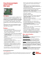
Control system description
®
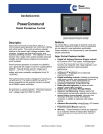
The PowerCommand control system is a microprocessorbased genset monitoring, metering and control system
designed to meet the demands of today’s engine driven
gensets. The integration of all control functions into a
single control system provides enhanced reliability and
performance, compared to conventional genset control
systems. These control systems have been designed and
tested to meet the harsh environment in which gensets are
typically applied.
Features
• 320 x 240 pixels graphic LED backlight LCD.
• Multiple language support.
• AmpSentry™ protection - for true alternator overcurrent
protection.
• Digital Power Transfer Control (AMF) provides load
•
•
•
•
•
•
•
•
•
•
•
•
•
transfer operation in open transition, closed transition, or
soft (ramping) transfer modes.
Extended Paralleling (Peak Shave/Base Load) regulates
the genset real and reactive power output while
paralleled to the utility. Power can be regulated at either
the genset or utility bus monitoring point.
Digital frequency synchronization and voltage matching.
Isochronous Load Share
Droop KW and KVAR Control
Real time clock for fault and event time stamping.
Exerciser clock and time of day start/stop initiate a test
with or without load, or a Base Load or Peak Shave
session.
Digital voltage regulation. Three phase full wave FET
type regulator compatible with either shunt or PMG
systems.
Genset monitoring and protection.
Utility/AC Bus metering and protection
12 and 24 VDC battery operation.
®
Modbus interface for interconnecting to customer
equipment.
Warranty and service. Backed by a comprehensive
warranty and worldwide distributor service network.
Certifications - Suitable for use on gensets that are
designed, manufactured, tested and certified to relevant
UL, NFPA, ISO, IEC, Mil Std. and CE standards.
©2008|Cummins Power Generation Inc.|All rights reserved|Specifications subject to change without notice|Cummins Power Generation
and Cummins are registered trademarks of Cummins Inc. PowerCommand, AmpSentry, InPower and “Our energy working for you.” are
trademarks of Cummins Power Generation. Other company, product, or service names may be trademarks or service marks of others.
S-1570 (4/08) Page 1 of 11
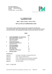
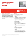
PowerCommand digital
genset control
PCC 3300
• Exerciser clock and time of day start/stop initiate a test
•
•
•
•
•
Description
The PowerCommand genset control is suitable for use on
a wide range of gensets in paralleling applications. The
PowerCommand control is compatible with shunt or PMG
excitation style. It is suitable for use with reconnectable or
non-reconnectable generators, and it can be configured
for any frequency, voltage and power connection from
120-600 VAC line-to-line, or 601-45,000 VAC with external
PT.
Power for this control system is derived from the genset
starting batteries. The control functions over a voltage
range from 8 VDC to 30 VDC.
Features
• 12 and 24 VDC battery operation.
• Digital voltage regulation - Three phase full wave FET
•
•
•
•
•
•
•
•
•
type regulator compatible with either shunt or PMG
systems. Sensing is three phase.
Full authority engine communications (where applicable)
- Provides communication and control with the Engine
Control Module (ECM).
AmpSentry™ protection - for true alternator overcurrent
protection.
Genset monitoring - Monitors status of all critical engine
and alternator functions.
Digital genset metering (AC and DC).
Genset battery monitoring system to sense and warn
against a weak battery condition.
Configurable for single or three phase AC metering.
Engine starting - Includes relay drivers for starter, fuel
shut off (FSO), glow plug/spark ignition power and
switch B+ applications.
Genset protection – Protects engine and alternator.
Real time clock for fault and event time stamping.
•
•
•
•
•
•
•
•
with or without load, or a Base Load or Peak Shave
session.
Digital Power Transfer Control (AMF) provides load
transfer operation in open transition, closed transition, or
soft (ramping) transfer modes.
Extended Paralleling (Peak Shave/Base Load) regulates
the genset real and reactive power output while
paralleled to the utility. Power can be regulated at either
the genset or utility bus monitoring point.
Digital frequency synchronization and voltage matching.
Isochronous Load Share
Droop KW and KVAR Control
Sync Check – The sync check function has adjustments
for phase angle window, voltage window, frequency
window and time delay.
Utility/AC Bus metering and protection
Advanced serviceability – using InPower™, a PC-based
software service tool.
Environmental protection – The control system is
designed for reliable operation in harsh environments.
The main control board is a fully encapsulated module
that is protected from the elements.
ModBus interface for interconnecting to customer
equipment.
Configurable inputs and outputs – Four discrete inputs
and four dry contact relay outputs.
Warranty and service – Backed by a comprehensive
warranty and worldwide distributor service network.
Certifications – Suitable for use on gensets that are
designed, manufactured, tested and certified to relevant
UL, NFPA, ISO, IEC, Mil Std. and CE standards.
Base control functions
HMI capability
Operator adjustments – The HMI includes provisions for
many set up and adjustment functions.
Genset hardware data – Access to the control and
software part number, genset rating in KVA and genset
model number is provided from the HMI or InPower.
Data logs – Includes engine run time, controller on time,
number of start attempts, total kilowatt hours, and load
profile. (Control logs data indicating the operating hours at
percent of rated kW load, in 5% increments. The data is
presented on the operation panel based on total operating
hours on the generator.)
Fault history – Provides a record of the most recent fault
conditions with control date and time stamp. Up to 32
events are stored in the control non-volatile memory.
Our energy working for you.™
www.cumminspower.com
©2008|Cummins Power Generation Inc.|All rights reserved|Specifications subject to change without notice|Cummins Power Generation
and Cummins are registered trademarks of Cummins Inc. PowerCommand, AmpSentry, InPower and “Our energy working for you.” are
trademarks of Cummins Power Generation. Other company, product, or service names may be trademarks or service marks of others.
S-1570 (4/08) Page 2 of 11
Alternator data
- Voltage (single or three phase line-to-line and line-toneutral)
- Current (single or three phase)
- kW, KVAR, power factor, KVA (three phase and total)
- Frequency
Utility/AC bus data
-
Voltage (three phase line-to-line and line-to-neutral)
Current (three phase and total)
kW, KVAR, power factor, KVA (three phase and total)
Frequency
Engine data
-
Starting battery voltage
Engine speed
Engine temperature
Engine oil pressure
Engine oil temperature
Intake manifold temperature
Comprehensive Full Authority Engine (FAE) data (where
applicable)
Service adjustments – The HMI includes provisions for
adjustment and calibration of genset control functions.
Adjustments are protected by a password. Functions
include:
- Engine speed governor adjustments
- Voltage regulation adjustments
- Cycle cranking
- Configurable fault set up
- Configurable input and output set up
- Meter calibration
- Paralleling setup
- Display language and units of measurement
Engine control
SAE-J1939 CAN interface to full authority ECMs (where
applicable). Provides data transfer between genset and
engine controller for control, metering and diagnostics.
12 VDC/24 VDC battery operations - PowerCommand will
operate either on 12 VDC or 24 VDC batteries.
Temperature dependent governing dynamics (with
electronic governing) - modifies the engine governing
control parameters as a function of engine temperature.
This allows the engine to be more responsive when warm
and more stable when operating at lower temperature
levels.
Isochronous governing - (where applicable) Capable of
controlling engine speed within +/-0.25% for any steady
state load from no load to full load. Frequency drift will not
exceed +/-0.5% for a 33 °C (60 °F) change in ambient
temperature over an 8 hour period.
Droop electronic speed governing - Control can be
adjusted to droop from 0 to 10% from no load to full load.
Remote start mode - It accepts a ground signal from
remote devices to automatically start the genset and
immediately accelerates to rated speed and voltage. The
remote start signal will also wake up the control from sleep
mode. The control can incorporate a time delay start and
stop.
Remote and local emergency stop - The control accepts a
ground signal from a local (genset mounted) or remote
(facility mounted) emergency stop switch to cause the
genset to immediately shut down. The genset is prevented
from running or cranking with the switch engaged. If in
sleep mode, activation of either emergency stop switch will
wakeup the control.
Sleep mode - The control includes a configurable low
current draw state to minimize starting battery current
draw when the genset is not operating. The control can
also be configured to go into a low current state while in
auto for prime applications or applications without a
battery charger.
Engine starting - The control system supports automatic
engine starting. Primary and backup start disconnects are
achieved by one of two methods: magnetic pickup or main
alternator output frequency. The control also supports
configurable glow plug control when applicable.
Cycle cranking - Is configurable for the number of starting
cycles (1 to 7) and duration of crank and rest periods.
Control includes starter protection algorithms to prevent
the operator from specifying a starting sequence that
might be damaging.
Time delay start and stop (cooldown) - Configurable for
time delay of 0-300 seconds prior to starting after receiving
a remote start signal and for time delay of 0-600 seconds
prior to shut down after signal to stop in normal operation
modes. Default for both time delay periods is 0 seconds.
Alternator control
The control includes an integrated three phase line-to-line
sensing voltage regulation system that is compatible with
shunt or PMG excitation systems. The voltage regulation
system is a three phase full wave rectified and has an FET
output for good motor starting capability. Major system
features include:
Digital output voltage regulation - Capable of regulating
output voltage to within +/-1.0% for any loads between no
load and full load. Voltage drift will not exceed +/-1.5% for
a 40 ºC (104 ºF) change in temperature in an eight hour
period. On engine starting or sudden load acceptance,
voltage is controlled to a maximum of 5% overshoot over
nominal level.
Our energy working for you.™
www.cumminspower.com
©2008|Cummins Power Generation Inc.|All rights reserved|Specifications subject to change without notice|Cummins Power Generation
and Cummins are registered trademarks of Cummins Inc. PowerCommand, AmpSentry, InPower and “Our energy working for you.” are
trademarks of Cummins Power Generation. Other company, product, or service names may be trademarks or service marks of others.
S-1570 (4/08) Page 3 of 11
The automatic voltage regulator feature can be disabled to
allow the use of an external voltage regulator.
Droop voltage regulation - Control can be adjusted to
droop from 0-10% from no load to full load.
Torque-matched V/Hz overload control - The voltage rolloff set point and rate of decay (i.e. the slope of the V/Hz
curve) is adjustable in the control.
Fault current regulation - PowerCommand will regulate the
output current on any phase to a maximum of three times
rated current under fault conditions for both single phase
and three phase faults. In conjunction with a permanent
magnet generator, it will provide three times rated current
on all phases for motor starting and short circuit
coordination purpose.
Paralleling functions
TM
First Start Sensor system – PowerCommand
provides a unique control function that positively prevents
multiple gensets from simultaneously closing to an isolated
bus under black start conditions. The First Start Sensor
system is a communication system between the gensets
that allows the gensets to work together to determine
which genset is a system should be the first to close to the
bus. The system includes an independent backup
function, so that if the primary system is disabled the
required functions are still performed.
Synchronizing – Control incorporates a digital
synchronizing function to force the genset to match the
frequency, phase and voltage of another source such as a
utility grid. The synchronizer includes provisions to
provide proper operation even with highly distorted bus
voltage waveforms. The synchronizer can match other
sources over a range of 60-110% of nominal voltage and
-24 to +6 hertz. The synchronizer function is configurable
for slip frequency synchronizing for applications requiring a
known direction of power flow at instant of breaker closure
or for applications where phase synchronization
performance is otherwise inadequate.
Load sharing control – The genset control includes an
integrated load sharing control system for both real (kW)
and reactive (kVar) loads when the genset(s) are operating
on an isolated bus. The control system determines kW
load on the engine and kVar load on the alternator as a
percent of genset capacity, and then regulates fuel and
excitation systems to maintain system and genset at the
same percent of load without impacting voltage or
frequency regulation. The control can also be configured
for operation in droop mode for kW or Kvar load sharing.
Load govern control – When PowerCommand receives
a signal indicating that the genset is paralleled with an
infinite source such as a utility (mains) service, the genset
will operate in load govern mode. In this mode the genset
will synchronize and close to the bus, ramp to a preprogrammed kW and kVar load level, and then operate at
that point. Control is adjustable for kW values from 0100% of standby rating, and 0.7-1.0 power factor
(lagging). Default setting is 80% of standby and 1.0 power
factor. The control includes inputs to allow independent
control of kW and kVar load level by a remote device while
in the load govern mode. The rate of load increase and
decrease is also adjustable in the control.
Load demand control – The control system includes the
ability to respond to an external signal to initiate load
demand operation. On command, the genset will ramp to
no load, open its paralleling breaker, cool down, and shut
down. On removal of the command, the genset will
immediately start, synchronize, connect, and ramp to its
share of the total load on the system.
Sync check – The sync check function decides when
permissive conditions have been met to allow breaker
closure. Adjustable criteria are: phase difference from 0.120deg, frequency difference from 0.001-1.0Hz, voltage
difference from 0.5-10%, and a dwell time from 0.5-5.0sec.
Internally the sync check is used to perform closed
transition operations. An external sync check output is
also available.
Genset and utility/AC bus source AC metering –
The control provides comprehensive three phase AC
metering functions for both monitored sources, including:
3-phase voltage (L-L and L-N) and current, frequency,
phase rotation, individual phase and totalized values of
kW, kVAR, kVA and Power Factor; totalized positive and
negative kW-hours, kVAR-hours, and kVA-hours. Three
wire or four wire voltage connection with direct sensing of
voltages to 600V, and up to 45kV with external
transformers. Current sensing is accomplished with either
5 amp or 1 CT secondaries and with up to 10,000 amp
primary. Maximum power readings are
32,000kW/kVAR/kVA.
Power transfer control – provides integrated automatic
power transfer functions including source availability
sensing, genset start/stop and transfer pair monitoring and
control. The transfer/retransfer is configurable for open
transition, fast closed transition (less than 100msec
interconnect time), or soft closed transition (load ramping)
sequences of operation. Utility source failure will
automatically start genset and transfer load, retransferring
when utility source returns. Test will start gensets and
transfer load if test with load is enabled. Sensors and
timers include:
Our energy working for you.™
www.cumminspower.com
©2008|Cummins Power Generation Inc.|All rights reserved|Specifications subject to change without notice|Cummins Power Generation
and Cummins are registered trademarks of Cummins Inc. PowerCommand, AmpSentry, InPower and “Our energy working for you.” are
trademarks of Cummins Power Generation. Other company, product, or service names may be trademarks or service marks of others.
S-1570 (4/08) Page 4 of 11
Under voltage sensor: 3-phase L-N or L-L under voltage
sensing adjustable for pickup from 85-100% of nominal.
Dropout adjustable from 75-98% of pickup. Dropout delay
adjustable from 0.1-30 sec.
Over voltage sensor: 3-phase L-N or L-L over voltage
sensing adjustable for pickup from 95-99% of dropout.
Dropout adjustable from 105-135% of nominal. Dropout
delay adjustable from 0.5-120 sec. Standard configuration
is disabled, and is configurable to enabled in the field
using the HMI or InPower service tools.
Over/Under frequency sensor: Center frequency
adjustable from 45-65 Hz. Dropout bandwidth adjustable
from 0.3-5% of center frequency beyond pickup
bandwidth. Pickup bandwidth adjustable from 0.3-20% of
center frequency. Field configurable to enable.
Loss of phase sensor: Detects out of range voltage phase
angle relationship. Field configurable to enable.
Exerciser clock –The exerciser clock (when enabled)
allows the system to be operated at preset times in either
test without load, test with load, or extended parallel
mode. A Real Time Clock is built in. Up to 12 different
programs can be set for day of week, time of day,
duration, repeat interval, and mode. For example, a test
with load for 1 hour every Tuesday at 2AM can be
programmed. Up to 6 different exceptions can also be set
up to block a program from running during a specific date
and time period.
Application types – Controller is configured to operating
in one of six possible application types. These topologies
are often used in combinations in larger systems, with
coordination of the controllers in the system either by
external device or by interlocks provided in the control.
Topologies that may be selected in the control include:
Standalone: Control provides monitoring, protection and
control in a non-paralleling application.
Phase rotation sensor: Checks for valid phase rotation of
source. Field configurable to enable.
Breaker tripped: If the breaker tripped input is active, the
associated source will be considered as unavailable.
Timers: Control provides adjustable start delay from 0300sec, stop delay from 0-800sec, transfer delay from 0120sec, retransfer delay from 0-1800sec, programmed
transition delay from 0-60sec, and maximum parallel time
from 0-1800sec.
Breaker control – Utility and Genset breaker interfaces
include separate relays for opening and closing breaker, as
well as inputs for both 'a' and 'b' breaker position contacts
and tripped status. Breaker diagnostics include Contact
Failure, Fail to Close, Fail to Open, Fail to Disconnect, and
Tripped. Upon breaker failure, appropriate control action
is taken to maintain system integrity.
Extended paralleling – In extended paralleling mode
(when enabled) the controller will start the genset and
parallel to a utility source and then govern the real and
reactive power output of the genset based on the desired
control point. The control point for the real power (kW) can
be configured for either the genset metering point ("Base
Load") or the utility metering point ("Peak Shave"). The
control point for the reactive power (kVAR or Power
Factor) can also be independently configured for either the
genset metering point or the utility metering point. This
flexibility would allow base kW load from the genset while
maintaining the utility power factor at a reasonable value to
avoid penalties due to low power factor. The System
always operates within genset ratings. The control point
can be changed while the system is in operation. Set
points can be adjusted via hardwired analog input or
adjusted through an operator panel display or service tool.
Synchronizer only: control will synchronize the genset to
other source when commanded to either via a hardwired or
Modbus driven input.
Isolated Bus: allows the genset to perform a dead bus
closure or synchronize to the bus and isochronously share
kW and kVAR loads with other gensets.
Our energy working for you.™
www.cumminspower.com
©2008|Cummins Power Generation Inc.|All rights reserved|Specifications subject to change without notice|Cummins Power Generation
and Cummins are registered trademarks of Cummins Inc. PowerCommand, AmpSentry, InPower and “Our energy working for you.” are
trademarks of Cummins Power Generation. Other company, product, or service names may be trademarks or service marks of others.
S-1570 (4/08) Page 5 of 11
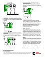
Power Transfer Control: control operates a single
genset/single utility transfer pair in open transition, fast
closed transition, or soft closed transition. Extended
paralleling functionality also provides base load and peak
shave options.
PCC
3300
G
Utility Single: Control monitors one genset and utility. The
control will automatically start and provide power to a load
if the utility fails. The control will also resynchronize the
genset back to the utility and provides extended paralleling
capabilities.
PCC
3300
G
Position Only
Protective functions
On operation of a protective function the control will
indicate a fault by illuminating the appropriate status LED
on the HMI, as well as display the fault code and fault
description on the LCD. The nature of the fault and time of
occurrence are logged in the control. The service manual
and InPower service tool provide service keys and
procedures based on the service codes provided.
Protective functions include:
Battle short mode
Utility Multiple: Supports all functionality of Isolated Bus
and provides extended paralleling to the utility. Extended
paralleling load set points follow a constant setting;
dynamically follow an analog input, Modbus register or
HMI.
When enabled and the battle short switch is active, the
control will allow some shutdown faults to be bypassed. If
a bypassed shutdown fault occurs, the fault code and
description will still be annunciated, but the genset will not
shutdown. This will be followed by a fail to shutdown fault.
Emergency stop shutdowns and others that are critical for
proper operation are not bypassed. Please refer to the
Control Application Guide or Manual for list of these faults.
Utility Parallel Enable
Derate
The Derate function reduces output power of the genset in
response to a fault condition. If a Derate command occurs
while operating on an isolated bus, the control will issue
commands to reduce the load on the genset via contact
closures or Modbus. If a Derate command occurs while in
utility parallel mode, the control will actively reduce power
by lowering the base load kW to the derated target kW.
Configurable alarm and status inputs
The control accepts up to four alarm or status inputs
(configurable contact closed to ground or open) to indicate
a configurable (customer-specified) condition.
Our energy working for you.™
www.cumminspower.com
©2008|Cummins Power Generation Inc.|All rights reserved|Specifications subject to change without notice|Cummins Power Generation
and Cummins are registered trademarks of Cummins Inc. PowerCommand, AmpSentry, InPower and “Our energy working for you.” are
trademarks of Cummins Power Generation. Other company, product, or service names may be trademarks or service marks of others.
S-1570 (4/08) Page 6 of 11
The control is programmable for warning, derate,
shutdown, shutdown with cooldown or status indication
and for labeling the input.
Emergency stop
Annunciated whenever either emergency stop signal is
received from external switch.
Full authority electronic engine protection
Engine fault detection is handled inside the engine ECM.
Fault information is communicated via the SAE-J1939 data
link for annunciation in the HMI.
General engine protection
Low and high battery voltage warning - Indicates status of
battery charging system (failure) by continuously
monitoring battery voltage.
Weak battery warning - The control system will test the
battery each time the genset is signaled to start and
indicate a warning if the battery indicates impending
failure.
Fail to start (overcrank) shutdown - The control system will
indicate a fault if the genset fails to start by the completion
of the engine crack sequence.
Fail to crank shutdown - Control has signaled starter to
crank engine but engine does not rotate.
Cranking lockout - The control will not allow the starter to
attempt to engage or to crank the engine when the engine
is rotating.
Fault Simulation –The control in conjunction with InPower
software, will accept commands to allow a technician to
verify the proper operation of the control and its interface
by simulating failure modes or by forcing the control to
operate outside of its normal operating ranges. InPower
also provides a complete list of faults and settings for the
protective functions provided by the controller.
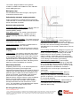
Alternator protection
AmpSentry protective relay - A UL-listed comprehensive
monitoring and control system integral to the
PowerCommand Control System that guards the electrical
integrity of the alternator and power system by providing
protection against a wide array of fault conditions in the
genset or in the load. It also provides single and three
phase fault current regulation so that downstream
protective devices have the maximum current available to
quickly clear fault conditions without subjecting the
alternator to potentially catastrophic failure conditions.
See document R1053 for a full size time over current
curve. The control does not included protection required
for interconnection to a utility (mains) service.
High AC voltage shutdown (59) - Output voltage on any
phase exceeds preset values. Time to trip is inversely
proportional to amount above threshold. Values adjustable
from 105-125% of nominal voltage, with time delay
adjustable from 0.1-10 seconds. Default value is 110% for
10 seconds.
Low AC voltage shutdown (27) - Voltage on any phase has
dropped below a preset value. Adjustable over a range of
50-95% of reference voltage, time delay 2-20 seconds.
Default value is 85% for 10 seconds. Function tracks
reference voltage. Control does not nuisance trip when
voltage varies due to the control directing voltage to drop,
such as during a V/Hz roll-off or synchronizing.
Under frequency shutdown (81 u) - Genset output
frequency cannot be maintained. Settings are adjustable
from 2-10 Hz below reference governor set point, for a 520 second time delay. Default: 6 Hz, 10 seconds. Under
frequency protection is disabled when excitation is
switched off, such as when engine is operating in idle
speed mode.
Over frequency shutdown/warning (81o) - Genset is
operating at a potentially damaging frequency level.
Settings are adjustable from 2-10 Hz above nominal
governor set point for a 1-20 second time delay. Default: 6
Hz, 20 seconds, disabled.
Overcurrent warning/shutdown (51) - Implementation of
the thermal damage curve with instantaneous trip level
calculated based on current transformer ratio and
application power rating.
Our energy working for you.™
www.cumminspower.com
©2008|Cummins Power Generation Inc.|All rights reserved|Specifications subject to change without notice|Cummins Power Generation
and Cummins are registered trademarks of Cummins Inc. PowerCommand, AmpSentry, InPower and “Our energy working for you.” are
trademarks of Cummins Power Generation. Other company, product, or service names may be trademarks or service marks of others.
S-1570 (4/08) Page 7 of 11
Loss of sensing voltage shutdown - Shutdown of genset
will occur on loss of voltage sensing inputs to the control.
Field overload shutdown - Monitors field voltage to
shutdown genset when a field overload condition occurs.
Maximum parallel time warning (power transfer control
mode only): During closed transition load transfers, control
independently monitors paralleled time. If time is
exceeded, warning is initiated and genset is disconnected.
Over load (kW) warning - Provides a warning indication
when engine is operating at a load level over a set point.
Adjustment range: 80-140% of application rated kW, 0120 second delay. Defaults: 105%, 60 seconds.
Bus or genset PT input calibration warning: The control
system monitors the sensed voltage from the bus and
genset output voltage potential transformers. When the
paralleling breaker is closed, it will indicate a warning
condition if the read values are different.
Reverse power shutdown (32) - Adjustment range: 5-20%
of standby kW rating, delay 1-15 seconds. Default: 10%,
3 seconds.
Field control interface
Reverse Var shutdown - Shutdown level is adjustable: 1550% of rated Var output, delay 10-60 seconds. Default:
20%, 10 seconds.
Short circuit protection - Output current on any phase is
more than 175% of rating and approaching the thermal
damage point of the alternator. Control includes
algorithms to protect alternator from repeated over current
conditions over a short period of time.
Paralleling protection
Breaker fail to close Warning: When the control signals a
circuit breaker to close, it will monitor the breaker auxiliary
contacts and verify that the breaker has closed. If the
control does not sense a breaker closure within an
adjustable time period after the close signal, the fail to
close warning will be initiated.
Breaker fail to open warning: The control system monitors
the operation of breakers that have been signaled to open.
If the breaker does not open within and adjustable time
delay, a Breaker Fail to Open warning is initiated.
Breaker position contact warning: The controller will
monitor both ‘a’ and ‘b’ position contacts from the
breaker. If the contacts disagree as to the breaker
position, the breaker position contact warning will be
initiated.
Breaker tripped warning: The control accepts inputs to
monitor breaker trip / bell alarm contact and will initiate a
breaker tripped warning if it should activate.
Fail to disconnect warning: In the controller is unable to
open either breaker, a fail to disconnect warning is
initiated. Typically this would be mapped to a configurable
output, allowing an external device to trip a breaker.
Fail to synchronize warning: Indicates that the genset
could not be brought to synchronization with the bus.
Configurable for adjustable time delay of 10 -900 seconds,
120 default.
Phase sequence sensing warning: Verifies that the genset
phase sequence matches the bus prior to allowing the
paralleling breaker to close.
Input signals to the PowerCommand control
include:
-
Coolant level (where applicable)
Fuel level (where applicable)
Remote emergency stop
Remote fault reset
Remote start
Rupture basin
Start type signal
Battle short
Load demand stop
Synchronize enable
Genset circuit breaker inhibit
Utility circuit breaker inhibit
Single mode verify
Transfer inhibit – prevent transfer to utility (in power
transfer control mode)
- Retransfer inhibit – prevent retransfer to genset (in power
transfer control mode)
- kW and kVAR load setpoints
- Configurable inputs - Control includes (4) input signals
from customer discrete devices that are configurable for
warning, shutdown or status indication, as well as
message displayed
Output signals from the PowerCommand control
include:
- Load dump signal: Operates when the genset is in an
overload condition.
- Delayed off signal: Time delay based output which will
continue to remain active after the control has removed
the run command. Adjustment range: 0 - 120 seconds.
Default: 0 seconds.
- Configurable relay outputs: Control includes (4) relay
output contacts (3 A, 30VDC). These outputs can be
configured to activate on any control warning or
shutdown fault as well as ready to load, not in auto,
common alarm, common warning and common
shutdown.
- Ready to load (genset running) signal: Operates when
the genset has reached 90% of rated speed and voltage
and latches until genset is switched to off or idle mode.
Our energy working for you.™
www.cumminspower.com
©2008|Cummins Power Generation Inc.|All rights reserved|Specifications subject to change without notice|Cummins Power Generation
and Cummins are registered trademarks of Cummins Inc. PowerCommand, AmpSentry, InPower and “Our energy working for you.” are
trademarks of Cummins Power Generation. Other company, product, or service names may be trademarks or service marks of others.
S-1570 (4/08) Page 8 of 11
- Paralleling circuit breaker relays outputs: Control
includes (4) relay output contacts (3.5A, 30 VDC) for
opening and closing of the genset and utility breakers.
Communications connections include:
- PC tool interface: This RS-485 communication port
allows the control to communicate with a personal
computer running InPower software.
- Modbus RS-485 port: Allows the control to
communicate with external devices such as PLCs using
Modbus protocol.
Note - An RS-232 or USB to RS-485 converter is
required for communication between PC and control.
- Networking: This RS-485 communication port allows
connection from the control to the other Cummins
Power Generation products.
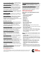
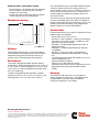
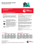
Mechanical drawing
Description
This control system includes an intuitive operator interface
panel that allows for complete genset control as well as
system metering, fault annunciation, configuration and
diagnostics. The interface includes five genset status LED
lamps with both internationally accepted symbols and
English text to comply with customers needs. The
interface also includes an LED backlit LCD display with
tactile feel soft-switches for easy operation and screen
navigation. It is configurable for units of measurement and
has adjustable screen contrast and brightness.
The run/off/auto switch function is integrated into the
interface panel.
All data on the control can be viewed by scrolling through
screens with the navigation keys. The control displays the
current active fault and a time-ordered history of the five
previous faults.
Features:
• LED indicating lamps
•
•
•
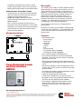
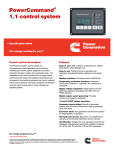
PowerCommand human
machine interface
HMI320
•
•
•
•
•
- genset running
- remote start
- not in auto
- shutdown
- warning
- auto
- manual and stop
- Circuit breaker open (if equipped)
- Circuit breaker closed (if equipped)
320 x 240 pixels graphic LED backlight LCD.
Four tactile feel membrane switches for LCD defined
operation. The functions of these switches are defined
dynamically on the LCD.
Seven tactile feel membrane switches dedicated screen
navigation buttons for up, down, left, right, ok, home and
cancel.
Six tactile feel membrane switches dedicated to control
for auto, stop, manual, manual start, fault reset and lamp
test/panel lamps.
Two tactile feel membrane switches dedicated to control
of circuit breaker (where applicable).
Allows for complete genset control setup.
Certifications: Suitable for use on gensets that are
designed, manufactured, tested and certified to relevant
UL, NFPA, ISO, IEC, Mil Std. and CE standards.
LCD languages supported: English, Spanish, French,
German, Italian, Greek, Dutch, Portuguese, Finnish,
Norwegian, Danish, Russian, Czech and Chinese
Characters.
Our energy working for you.™
www.cumminspower.com
©2008|Cummins Power Generation Inc.|All rights reserved|Specifications subject to change without notice|Cummins Power Generation
and Cummins are registered trademarks of Cummins Inc. PowerCommand, AmpSentry, InPower and “Our energy working for you.” are
trademarks of Cummins Power Generation. Other company, product, or service names may be trademarks or service marks of others.
S-1570 (4/08) Page 9 of 11
Communications connections include:
- PC tool interface - This RS-485 communication port
allows the HMI to communicate with a personal
computer running InPower.
- This RS-485 communication port allows the HMI to
communicate with the main control board.
Mechanical drawing
The control board is fully encapsulated to provide superior
resistance to dust and moisture. Display panel has a
single membrane surface, which is impervious to effects of
dust, moisture, oil and exhaust fumes. This panel uses a
sealed membrane to provide long reliable service life in
harsh environments.
The control system is specifically designed and tested for
resistance to RFI/EMI and to resist effects of vibration to
provide a long reliable life when mounted on a genset. The
control includes transient voltage surge suppression to
provide compliance to referenced standards.
Certifications
PowerCommand meets or exceeds the requirements of the
following codes and standards:
Software
InPower (beyond 6.5 version) is a PC-based software
service tool that is designed to directly communicate to
PowerCommand gensets and transfer switches, to
facilitate service and monitoring of these products.
Environment
The control is designed for proper operation without
recalibration in ambient temperatures from -40 ºC (104 ºF)
to +70º C (158 ºF), and for storage from -55 ºC (131 ºF) to
+80 ºC (176 ºF). Control will operate with humidity up to
95%, non-condensing.
The HMI is designed for proper operation in ambient
temperatures from -20 ºC (-4 ºF) to +70 ºC (158 ºF), and
for storage from -30 ºC (-22 ºF) to +80 ºC (176 ºF).
- NFPA 110 for level 1 and 2 systems.
- ISO 8528-4: 1993 compliance, controls and switchgear.
- CE marking: The control system is suitable for use on
generator sets to be CE-marked.
- EN 50081-1,2 residential/light industrial emissions or
industrial emissions.
- EN 50082-1,2 residential/light industrial or industrial
susceptibility.
- ISO 7637-2, level 2; DC supply surge voltage test.
- Mil Std 202C, Method 101 and ASTM B117: Salt fog
test.
- UL 508 recognized or Listed and suitable for use on UL
2200 Listed generator sets.
- CSA C282-M1999 compliance
- CSA 22.2 No. 14 M91 industrial controls.
- PowerCommand control systems and generator sets are
designed and manufactured in ISO 9001 certified
facilities.
Warranty
All components and subsystems are covered by an
express limited one year warranty. Other optional and
extended factory warranties and local distributor
maintenance agreements are available.
Our energy working for you.™
www.cumminspower.com
©2008|Cummins Power Generation Inc.|All rights reserved|Specifications subject to change without notice|Cummins Power Generation
and Cummins are registered trademarks of Cummins Inc. PowerCommand, AmpSentry, InPower and “Our energy working for you.” are
trademarks of Cummins Power Generation. Other company, product, or service names may be trademarks or service marks of others.
S-1570 (4/08) Page 10 of 11
See your distributor for more information
Cummins Power Generation
Americas
rd
1400 73 Avenue N.E.
Minneapolis, MN 55432 USA
Phone: 763 574 5000
Fax: 763 574 5298
Europe, CIS, Middle East and Africa
Manston Park Columbus Ave.
Manston Ramsgate
Kent CT 12 5BF United Kingdom
Phone 44 1843 255000
Fax 44 1843 255902
Asia Pacific
10 Toh Guan Road #07-01
TT International Tradepark
Singapore 608838
Phone 65 6417 2388
Fax 65 6417 2399
Warning: Back feed to a utility system can cause electrocution and/or property damage. Do not connect to any building’s electrical system
except through an approved device or after building main switch is open.
Our energy working for you.™
www.cumminspower.com
©2008|Cummins Power Generation Inc.|All rights reserved|Specifications subject to change without notice|Cummins Power Generation
and Cummins are registered trademarks of Cummins Inc. PowerCommand, AmpSentry, InPower and “Our energy working for you.” are
trademarks of Cummins Power Generation. Other company, product, or service names may be trademarks or service marks of others.
S-1570 (4/08) Page 11 of 11