1
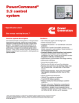
GenSet Controls PowerCommand Digital Paralleling Control PowerCommand Operator Panel, including graphical display and analog AC metering. Features Description The PowerCommand™ Control (PCC 3200) is a microprocessor-based generator set monitoring, metering, and control system. The control provides an operator interface to the genset, digital voltage regulation, digital governing, generator set protective functions, and automatic paralleling functions. The integration of all the functions into a single control system provides enhanced reliability and performance compared to conventional control systems. PowerCommand generator set controls are suitable for use on generator set ranging in size from roughly 20kW to 4000 kW. They will directly read AC voltages up to 600VAC, and can be configured for any frequency, voltage, and power connection configuration from 12013,800VAC. The PowerCommand control is designed for mounting on the generator set. The operator panel may also be remote-mounted from the generator set, and connected via an RS485 network connection. Control power for PowerCommand is usually derived from the generator set starting batteries. The control functions over a voltage range from 8VDC to 35VDC. The control offers a wide range of standard control and digital display features so custom control configurations are not needed to meet application specifications. System reliability is not compromised by use of untested special components. Major Control Features Include: • • • • • • • • • • • • © 2002 Cummins Power Generation Digital Full Authority Electronic Engine Controls for Cummins HPI-PT fuel system, including engine monitoring and protection, and governing. These functions are integrated with voltage regulation, and paralleling functions for optimum system performance. Digital Voltage Regulation AmpSentry™ Protection for true alternator overcurrent protection. Digital Paralleling Controls, including synchronizing, load sharing controls, and import/export controls for paralleling with an infinite (utility/mains) bus. Analog and Digital AC Output Metering. Battery Monitoring System to sense and warn against a weak battery condition. Digital Alarm and Status Message Display Generator set Monitoring: Displays status of all critical engine and alternator generator set functions. Smart Starting Control System: Integrated fuel ramping to limit black smoke and frequency overshoot, in addition to optimized cold weather staring. Advanced Serviceability using InPower, a PC-based software service tool. PowerCommand Network (optional). Warranty. PowerCommand Controls are supported by a worldwide network of independent distributors who provide parts, certified service and warranty support. Specifications Subject to Change S1385d 1/2002 Operator Panel The operator panel provides the user with a complete package of easy to view and use information. It includes an enhanced graphical operator panel that allows the user to view up to 9 lines of information, as well as graphical displays of system data. Connections to the operator panel are sealed locking plug interfaces, for reliable, vibration-resistant interconnection to the generator set wiring harness. Control Switches and Functions via raise/lower switches on the operator panel. Functions that can be adjusted by the operator include: Time delay start (0-300 seconds) Time delay stop (0-600 seconds) Alternator voltage (plus or minus 5%) Alternator frequency (plus or minus 3 hertz). The operator panel can be configured to require an access code prior to adjusting these values. A second access code is used to protect the control from unauthorized service level adjustments. Voltage and frequency adjustments are disabled during operation in parallel with a system bus to prevent inadvertent misadjustment of the paralleling load sharing functions. PowerCommand Analog AC Metering Display Analog AC Metering Panel OFF/MANUAL/AUTO Mode Control Switch - The NOT IN AUTO lamp will flash when the control is in the MANUAL or OFF mode. In the AUTO mode, the generator set can be started using the exercise pushbutton, or with a start signal from a remote device, such as automatic transfer switches. MANUAL RUN/STOP Control Switch And Indicating LED - When the mode control switch is in the MANUAL position and the MANUAL RUN /STOP switch is pressed, the Generator set will start, bypassing all time delays for idle mode or time delay start. If the generator set is running in the MANUAL mode, pressing the RUN/STOP switch will cause the generator set to shut down. An LED (light emitting diode) lamp adjacent to the switch will light to indicate the generator set is in manual mode. EXERCISE Control Switch And Indicating LED When the mode control switch is in the AUTO mode the EXERCISE control switch is used to complete a pre-programmed exercise sequence. All exercise functions are disabled when an emergency start command is received by the control. An LED lamp adjacent to the switch will light to indicate the generator set is in exercise mode. PANEL LAMP/LAMP TEST Control Switch EMERGENCY STOP Control Switch Operator Adjustments - The control includes provisions for many set up and adjustment functions © 2002 Cummins Power Generation The PowerCommand control is equipped with an analog AC metering panel that simultaneously displays 3-phase line to line AC volts and current, kW, power factor, and frequency. The meter panel is composed of a series of LED’s configured in bar graphs for each function. The LED’s are color coded, with green indicating normal range values, amber for warning levels, and red for shutdown conditions. Scales for each function are in % of nominal rated values. Resolution is 1% for values close to nominal, and increases at increasing values from nominal. Specifications Subject to Change S1385d 1/2002 Graphical Display Panel The PowerCommand control is provided with a graphical display capable of displaying up to 9 lines of data with approximately 27 characters per line. The graphical display is accompanied by a set of six tactile feel membrane switches that are used by the operator to navigate through control menus, and to make control adjustments. Display is configurable for multiple languages, including character-based languages. It is configurable for units of measurement. The display incorporates three levels of operation and adjustability. All data on the control can be viewed by scrolling through screens with the navigation keys. The top three lines of the display are allocated to mode and status messages that continuously display the operating mode of the control system, as well as any faults or warning conditions that may be present on the controller. If more than one fault or warning message is present the messages will scroll to allow the operator to view all active messages in the system. • Generator Set Hardware Data - Generator set rating in kVA, complete Generator set model number and serial number, engine model and serial number, and alternator model and serial number. The control also displays the part number of the control and the software version present in the control. Data Logs - Number of start attempts and number of start attempts since reset. Number of times generator set has run and number of times since reset. Duration of generator set running time, and duration of running time since last reset. Generator set kWh produced, and kWh produced since last reset. Adjustment History - Provides a record of adjustment and setting changes made on the control, and identifies whether adjustment was made via the operator panel or with a service tool. If a service tool is used, the control provides a record of the serial number of the tool used. This information is read with InPower. Fault History - Provides a record of the most recent fault conditions with time stamp, along with the number of times each fault has occurred. At least 20 events are stored in the control memory. Load Profile Data - Provides data indicating the operating hours at percent of load, in 10% © 2002 Cummins Power Generation increments. The data is presented based on total operating hours on the generator set, and also on the loads on the generator set since. Generator Set Output Voltage - all phases, line to line and line to neutral, accuracy 1%. Generator Set Output Current - all phases, accuracy 1%. Generator Set Output Frequency Generator Set Power Output - PowerCommand displays generator set kW and kVA output (average and individual phase, and direction of flow), and power factor with leading/lagging indication. Accuracy 5%. Generator Set kWh Power Output - Displays total kilowatt-hours produced by the generator set, and total produced since last reset, with time stamp of time of last reset. Digital Synchroscope - Panel displays bus voltage and frequency; generator set bus voltage and frequency, the phase angle displacement, and provides a signal when the generator is ready to close to the bus. A breaker control switch is included on this panel for convenient operation of the equipment without switching between viewing screens. Basic Engine Data - Engine Starting Battery Voltage, Engine Lube Oil Pressure, Engine Coolant Temperature Engine Service Data - Engine Coolant Pressure Engine Fuel Rail Temperature and Pressure, Engine Fuel Input And Output Temperature, Intake Manifold Temperature And Pressure, Ambient Air Pressure, Crankcase Blowby Flow, Aftercooler Inlet Coolant Temperature Engine Fuel Consumption - The fuel consumed by the engine is calculated by the control based on fuel flow into the engine and returned by the engine, and the temperature of the two flow streams. Accuracy is + 5% over 500 hours of operation. Data provided includes overall average fuel consumed, consumption since reset. This information is read with InPower. Engine Exhaust Temperature (optional) Internal Control Functions General Functions Emergency Start Mode - PowerCommand accepts a ground signal from remote devices or a network signal to automatically start the generator set and immediately accelerate to rated speed and voltage. PowerCommand includes a Smart StartingTM system that is designed to quickly start the engine, minimize black smoke, and minimize voltage and frequency overshoot and oscillations on starting. The control system does this by careful simultaneous control of the engine fuel system and alternator excitation system. Specifications Subject to Change S1385d 1/2002 Non-Emergency Start Mode - The control is provided with a separate remote start input or a network signal to start the generator set via the programmable idle control. Using the non-emergency mode, the generator set takes longer to start, but there is less wear on the engine. In this start mode, the generator set will start, operate at idle speed for a predefined time period or until the engine reaches operating temperature (whichever is time is shorter), and then ramp to rated speed and voltage. Time delay is adjustable from 0-300 seconds, and default is 10 seconds. The control also monitors and records the source of start signals, when that information is available. The control automatically exits idle mode if an emergency remote start signal is received at the control. Screen-Saver Mode - PowerCommand can be programmed to automatically switch off the operator panel displays to reduce battery voltage drain when the control is not being used and the generator set is not running. Depressing any button on the operator panel, new fault conditions or receipt of a remote signal at the control will “wake up” the control. Data Logging - The control maintains a record of manual control operations, warning and shutdown conditions, and other events. It uses the control “ON” time as the time stamp means when a real time clock is not included with the control. The control also stores critical engine and alternator data before and after a fault occurs, for use by InPower and the technician in evaluating the root causes for the fault condition. Fault Simulation Mode - PowerCommand, in conjunction with InPower software, will accept commands to allow a technician to verify the proper operation of all protective functions of the control, by simulating failure modes or by forcing the control to operate outside of its normal operating ranges. InPower also provides a complete list of faults and settings for the protective functions of the specific generator set it is communicating with. Built In Test - The control system automatically tests itself, and all the sensors, actuators and harnesses in the control system on a startup signal. The test can also be initiated from InPower, and can be accomplished either local to the generator set or remotely. First Start Sensor System - PowerCommand incorporates a unique control system that is designed to prevent more than one generator set from closing to a dead bus under black start conditions. The First Start Sensor continuously communicates with other PowerCommand generator sets and when it is ready to close to a dead bus, will verify that no other generator set is closing its breaker, and then lock out all other generator sets from closing to the bus. This function eliminates the possibility that a generator set might accidentally close to the bus out of phase with another oncoming generator set. If the first sensor input to the control is lost, the control reverts to a digital “dead bus” mode and indicates an alarm condition. Synchronizer - PowerCommand incorporates a digital synchronizing function to force the generator set to match © 2002 Cummins Power Generation the phase relationship of its output and the system bus, and to match the voltage of the generator set output with the system bus. The synchronizer includes provisions to provide proper operation even with highly distorted bus voltage waveforms. The synchronizer operates over a range of 60-110% of nominal voltage and frequency, and includes adjustments for phase angle window (5-20 degrees) and time delay (0.5-5 seconds). Load Share Mode – PowerCommand includes automatic load sharing control functions to allow isochronous load sharing for both kW and kVar loads between PowerCommand generator sets. Load sharing between PowerCommand generator sets will be within 1% of equal for all load levels from no load to full load. An accessory module is available to allow KW load sharing to systems manufactured by others. Load Demand Mode - On receipt of a signal from a remote device (discrete or via network), the control will cause the generator set to ramp down to a minimum kW and kVar level, switch open the paralleling breaker, operate for a predefined cooldown period, and then shutdown until called to restart. The control displays a message indicating the generator set is in a load demand shutdown condition when shut down in this mode. When the load demand signal is removed from the generator set, the control will start the generator set, complete the preprogrammed starting cycle, synchronize the generator set to the bus, close at no load, then ramp kW and kVar load to its proportional share of the total load on the bus. The load demand mode with ramping capability allows generator sets to leave and reacquire the bus without imposing sudden load changes that might cause frequency and voltage fluctuations in the system. The system includes provisions for an emergency start if the bus is overloaded or if one of the other generator sets in the system fails. Load Govern Mode - When PowerCommand receives a signal indicating that the generator set is paralleled with an infinite source, such as a utility (mains) service, the generator set will operate in load govern mode. In this mode, the generator set will synchronize and close to the bus and ramp to a pre-programmed kW and kVar load level, and then operate at that point. Control is adjustable for kW values from 0-100% of standby rating, and 0.7-1.0 power factor (leading). Default setting is 80% of standby and 1.0 power factor. The control includes inputs to allow independent control of kW and kVar load sharing level by a remote device while in the load govern mode. The rate of load increase and decrease is also adjustable in the control. Manual (Semi-Automatic) Parallel Mode - When the mode select switch is in the manual position, the paralleling breaker can be closed by operating a control switch adjacent to the display panel. PowerCommand will attempt to synchronize the generator set to the system bus, but will not automatically close the paralleling breaker. The operator can observe the condition of the generator set output relative to the bus on a Digital Specifications Subject to Change S1385d 1/2002 Synchroscope display in the operator panel. The panel graphically displays displacement from synchronous condition, bus and generator voltage, and bus and generator set frequency. Alternator Control Engine Control Engine Starting - The control operates a factorysupplied fuel valve that enables engine starting. Cycle Cranking - Configurable for number of starting cycles (1 to 7) and duration of crank and rest periods. Control includes starter protection algorithms to prevent the operator from specifying a starting sequence that might be damaging. Default setting is for (3) start cycles composed of 15 seconds of cranking, and 15 seconds of rest. Programmable Idle Speed Control - In this mode the generator set would start and run to idle speed. It would operate at that speed for a programmed time period, and then ramp to rated speed. When the control gets a signal to stop, it will ramp to idle, operate for the programmed period at idle, and then shut down. During idle mode engine protective functions are adjusted for the lower engine speed, and alternator function is disabled. Time Delay Start And Stop (cooldown) Configurable for time delay of 0-300 seconds prior to starting after receiving a remote start signal, and for time delay of 0-600 seconds prior to ramp to idle or shut down after signal to stop in normal operation modes. The generator set control will monitor the load during operation of the generator set, and if the total load on the set is less than 10% of rated, it will reduce the operation time for the time delay stop to prevent extended operation of the engine at very light load levels. Default for both time delay periods is 0 seconds. Engine Governing Isochronous Governing - Controls engine speed within plus or minus 0.25% for any steady state load from no load to full load. Frequency drift will not exceed plus or minus 0.5% for a 60F (33C) change in ambient temperature over an 8 hour period. Droop Governing - Control can be adjusted to droop from 0 to 10% from no load to full load, using InPower. Temperature Dynamics - Modifies the engine fuel system control parameters as a function of engine temperature. Allows engine to be more responsive when warm, and more stable when operating at lower temperature levels. Isochronous Load Sharing Control – see General Functions. Droop Load Sharing Control– see General Functions. Idle Mode - Engine governing can be regulated at an idle speed for a programmed period on start or stop of the engine. When the engine is operating at idle speed, the alternator excitation is automatically switched off. © 2002 Cummins Power Generation Digital Output Voltage Regulation PowerCommand will regulate output voltage to within 0.5% for any loads between no load and full load. Voltage drift will not exceed plus or minus 0.5% for a 60F (33C) change in temperature in an 8 hour period. On engine starting, or sudden load acceptance, voltage is controlled to a maximum of 5% overshoot over nominal level. Torque-Matched Volts/Hz Overload Control - The voltage roll-off set point and rate of decay (i.e., the slope of the volts/hertz curve) is adjustable in the control. This function is automatically disabled when the control is in a synchronizing mode. Fault Current Regulation - PowerCommand will regulate the output current on any phase to a maximum of 3 times rated current under fault conditions for both single phase and three phase faults. In conjunction with a permanent magnet generator, it will provide 3 times rated current on all phases for motor starting and short circuit coordination purposes. Isochronous (kVar) Load Sharing Control – see General Functions. Droop (kVar) Load Sharing Control – see General Functions. Protective Functions On a warning condition the control will indicate a fault by lighting the warning LED on the control panel, and displaying the fault name and code on the operator display panel. The nature of the fault and time of occurrence are logged in the control. The service manual and InPower service tool provide service keys and procedures based on the service codes provided. On a shutdown condition, the control will light the shutdown LED on the control panel, display the fault name and code, and initiate shut down and lock out the generator set. The shutdown sequence of the generator set includes programmable cooldown at idle for fault conditions that do not endanger the engine. The control maintains a data log of all fault conditions as they occur, and time stamps them with the controller run time and engine operating hour’s data. Adjustments to most set points are made using the InPowerTM service tool. The control system includes a “fault bypass” mode that forces the system to function regardless of the status of protective functions. In this mode the only protective functions that are operational are Overspeed, loss of both speed sensors, or moving the control switch to the off position, or pressing the EMERGENCY STOP switch. The control maintains a record of the time that the mode is enabled, and all warning or shutdown conditions that have occurred while in the “fault bypass” mode. Many protective functions within the control system are configurable for warning, shutdown, or both (2 levels). Exceptions to this include functions such as overspeed conditions, and loss of speed sensing. In addition, some Specifications Subject to Change S1385d 1/2002 warning functions can incorporate control functions as a consequence of a fault. PowerCommand provides the following system protective functions: Ground Fault Warning (option- 600VAC class generator sets) - Ground (Earth) fault sensing is adjustable over a range of 100-1200 amps, with time delays of 0-1 second. May be configured for shutdown rather than alarm. Configurable Alarm and Status Inputs PowerCommand will accept up to four alarm or status inputs (contact closed to ground) to indicate customer-specified conditions. The control is programmable for warning, shutdown or status indication, and for labeling the input (up to 24 characters). Four additional faults can be input to the control via the network. Breaker Fail To Close And Breaker Auxiliary Contact Warning Or Shutdown - When the paralleling control signals a circuit breaker to close, it will monitor the breaker auxiliary contacts and verify that the breaker has connected the generator set to the system bus. If the control does not sense a breaker closure within 1 second of the close signal, the control will monitor the phase relationship between the generator set and the bus. If this indicates that the generator set is not closed to the bus, the Breaker Fail to Close alarm will be indicated, the breaker will be opened, and the generator set shut down. If the phase relationship monitor indicates that the generator set is in parallel with the bus, the Breaker Auxiliary Contact Failure will be indicated, and the generator set will continue to run in normal operation mode. Breaker Fail To Open Warning - The control system monitors the operation of breakers that have been signaled to open. If the breaker does not open within 1 second of initiation of signal, a Breaker Fail to Open warning is initiated. The control will logically allow the generator set to continue to run if shutdown of the generator set with the breaker closed will cause potential damage or operating problems. Bus Or Generator Set PT Input Calibration Error The control system monitors the sensed voltage from the bus and generator set output voltage potential transformers, and will indicate a warning condition when they read different values when the paralleling breaker is closed. Emergency Stop - Annunciated whenever the local or remote emergency stop signal is received. Alarm panel distinguishes between local or remote operation. AmpSentryTM AmpSentry is a comprehensive monitoring and control system integral to the PowerCommand control that guards the electrical integrity of the alternator and power system by providing protection against a wide array of fault conditions in the generator set or in the load. It also provides single and 3-phase fault current regulation, so © 2002 Cummins Power Generation ALTERNATOR THERMAL DAMAGE CURVE AMPSENTRY OVERCURRENT PROTECTION CURVE 10 Seconds 1 0.03 1 10 Amps ( x rated) that downstream protective devices have the maximum current available to quickly clear fault conditions, without subjecting the alternator to potentially catastrophic failure conditions. Functions included: Over Current Warning - Output current on any phase at more than 110% of rating for more than 60 seconds. Over Current Shutdown (51) - Output current on any phase is more than 110%, less than 175% of rating, and approaching thermal damage point of alternator. Control includes algorithms to protect alternator from repeated over current conditions over a short period of time. Short Circuit Shutdown -Output current on any phase is more than 110%, more than 175% of rating, and approaching thermal damage point of alternator. Control includes algorithms to protect alternator from repeated over current conditions over a short period of time. High AC Voltage Shutdown (59) - Output voltage on any phase exceeds preset values. Time to trip is inversely proportional to amount above threshold. Values adjustable from 105-125% of nominal voltage, with time delay adjustable from 0.25-10 seconds. Default value is 110% for 10 seconds. Low AC Voltage Shutdown (27) - Voltage on any phase has dropped below a preset value. Adjustable over a range of 50-95% of reference voltage, time delay 2-10 seconds. Default value is 85% for 10 seconds. Function tracks reference voltage. Control does not nuisance trip when voltage varies due to the control directing voltage to drop, such as during a voltage roll-off during synchronizing. Specifications Subject to Change S1385d 1/2002 Under Frequency Shutdown (81u) - Generator set output frequency cannot be maintained. Settings are adjustable from 0-10 hertz below nominal governor set point, for a 0-20 second time delay. Default: 6Hz, 10 seconds. Under frequency protection is disabled when excitation is switched off (such as when engine is operating in idle speed mode or the synchronizer is enabled). Over Frequency Shutdown/Warning (81o) Generator set is operating at a potentially damaging frequency level. Defaults: Disabled. Over Load (kW) Warning - Provides a warning indication when engine is operating at a load level over a set point. Adjustment range: 80-140% of rated kW, 0-120 second delay. Defaults: 105%, 60 seconds. Reverse Power Shutdown (32) - Adjustment range: 5-20% of standby kW rating, delay 1-15 seconds. Defaults: 10%, 3 seconds. Sync Check (25) - Verifies that the generator set is operating in synchronism with the system bus prior to allowing the paralleling breaker to close. Includes dead bus sensing capability. Fail To Synchronize Warning Or Shutdown Indicates that the generator set could not be brought to synchronization with the system bus. Configurable for warning or shutdown, and adjustable for time delay of 10-120 seconds. Default is 120 seconds. Phase Sequence Sensing Shutdown - Verifies that the generator set phase sequence matches the bus prior to allowing the paralleling breaker to close. The generator set will shutdown if the generator set and bus phase sequence does not match. Reverse Var Shutdown - Shutdown level is adjustable: 15-50% of rated Var output, delay 10-60 seconds. Defaults: 20%, 10 seconds. High Alternator Temperature (Option) Engine Protection Overspeed Shutdown - Default setting is 115% of nominal. Low Lube Oil Pressure Shutdown - Level is preset to match the capabilities of each engine. Control includes time delays to prevent nuisance shutdown signals. Low Lube Oil Pressure Warning - Level is preset to match the capabilities of each engine. Control includes time delays to prevent nuisance shutdown signals. High Coolant Temperature Shutdown High Coolant Temperature Warning Low Coolant Pressure Warning/Shutdown Low Coolant Level Warning/Shutdown Low Coolant Temperature Warning. Indicates that engine temperature may not be high enough for a 10 second start or proper load pickup. Low and High Battery Voltage Warning - Indicates battery charging system failure by continuously monitoring battery voltage and indicating a problem when voltage is outside a preset acceptance band. © 2002 Cummins Power Generation Discharged Battery Protection. When DC voltage is below a preset threshold the control will shut down to avoid completely discharging the battery. Weak Battery Warning - The control system will test the battery bank each time the generator set is signaled to start, and indicate a warning if the generator set battery indicates impending failure. Fail to Start (Overcrank) Shutdown Fail to Crank Shutdown - Control has signaled starter to crank engine but engine does not rotate. Redundant Starter Disconnect Redundant Speed Sensors - Loss of one sensor results in a Mag Pickup sensor warning. Loss of both sensors results in Mag Pickup Failure. Low Fuel-Day Tank and Low Fuel-Main Tank warning. Cranking Lockout. The control will not allow the starter to attempt to engage or to crank the engine when the engine is rotating. Sensor Failure Indication. All analog sensors are provided with sensor failure logic to indicate if the sensor or interconnecting wiring has failed. Separate indication is provided for fail high or low. High Crankcase Blowby Level warning. High Fuel Temperature Warning. High Intake Manifold Temperature/Pressure Aftercooler Cooler Inlet Over Temperature Control Interface Input signals to the PowerCommand control include: Remote Start signal. May be connected via either discrete signal or Lon network, or both for premium reliability. Discrete signal is normally open contact to ground, or normally closed contact that opens to indicate start signal. Separate signal inputs available for emergency start and non-emergency start. Remote Emergency Stop. Configurable Customer Inputs. Control includes provisions for (4) input signals from customer discrete devices. Low Main or Daytank Fuel Level warning. Remote Alarm Reset Load Demand Stop. Utility Parallel (Load Govern) Mode command. Output signals from the control include: Generator Set Running signal. Fused normally open contact rated 5A @ 30VDC/180VAC, closes to indicate generator set is running. Generator Set Common Shutdown signal. Selfprotected relay driver. Load Shed signal. Self-protected relay driver. Operation is configurable for under frequency or over kW load, or both. Default settings are: overload: 105%, 60 sec; under frequency: 3 Hz below governor reference for 3 seconds. Ready to Load signal. Self-protected relay driver. Operates when the generators sets has reached 90% of rated speed and voltage and latches until generator set is switched to off or idle mode. Modem Control signal. Self-protected relay driver. Specifications Subject to Change S1385d 1/2002 Paralleling Breaker Interface. Fused normally open relay contact (5A, 30Vdc/180Vac) for parallel breaker close signal, and normally open contact for parallel breaker open signal. Control power for auxiliary devices is available from the controller. Network connections include: Serial Interface. This communication port is to allow the control to communicate with a personal computer running InPower service and maintenance software. Echelon LonWorks Interface (Option). PowerCommand generator sets incorporating this option are LonMarkTM compliant. Software InPower InPower is a PC-based software service tool that is designed to directly communicate to PowerCommand generator sets and transfer switches to facilitate service and monitoring of these products. PowerCommand for Windows PowerCommand for Windows is a software tool that is used to remotely monitor and control generator sets, transfer switches, and other on-site power system devices. Options and Accessories Certifications PowerCommand meets or exceeds the requirements of the following codes and standards: NFPA110 for level 1 systems. UL508 Listed, Category NIWT7 for US and Canada. CSA C282-M1999 Compliance CSA 22.2 No. 14 M91 Industrial Controls. ISO 8528-4: 1993 Compliance, Controls and Switchgear NFPA99: Standard for Health Care Facilities EC Marking EN 50081-1 residential, commercial, light industrial EN 50081-2 Industrial EN 50082-1 residential, commercial, light industrial EN 50082-2 Industrial ISO 7637, pulses #2b, 4; DC supply surge voltage test. Mil Std 202C, Method 101 Salt Fog test ANSI C62.41 Surge Withstand Mil Std 461 IEC 801.2, 3, 4, 5 IEEE 587 PowerCommand control systems and generator sets are designed and manufactured in ISO9001 certified facilities. Key-type Mode Select Switch. Ground Fault Alarm Module. Semi-Automatic Environment Warranty The control is designed for proper operation without recalibration in ambient temperatures from –40C to +70C, and for storage from –40C to +80C. Control will operate with humidity up to 95%, non-condensing, and at altitudes up to 13,000 feet (5000 meters). PowerCommand control systems are a part of complete power systems provided by Cummins Onan, and are covered by a one-year limited warranty as a standard feature. The operator control panel is a NEMA 3R/IP53 enclosure. The operator control panel has a single membrane surface, which is impervious to the effects of dust, moisture, oil, and exhaust fumes. The panel uses sealed membrane or oil-tight switches to provide long reliable service life in harsh environments. Paralleling. Provides an operator with the capability of synchronizing the generator set to an isolated system bus, and manually initiating operation of the paralleling breaker. System includes the protective functions described in this document, but will not automatically close the paralleling breaker. Upgradable to higher order paralleling functions in the field. Isolated Bus Paralleling. Provides all automatic and manual paralleling functions for systems that operate isolated from the utility service. Full Function Paralleling. Provides all paralleling functions, including automatic and manual operation, protection, and other features described in this document. Exhaust Temperature Monitoring Alternator Temperature Monitoring Digital Remote Annunciator Digital Output Relay Module Extended warranty options are available for coverage up to 10 years. The control system is specifically designed for resistance to RFI/EMI, and to resist the effects of vibration to provide a long reliable life when mounted on a generator set. The control includes transient voltage surge suppression to provide compliance to referenced standards. © 2002 Cummins Power Generation Specifications Subject to Change S1385d 1/2002 Bolt-on Access Panel Bolt-on Access Panel 1407 700 420 Optional PowerCommand Free-Standing Control Dimensions (mm) See your distributor for more information Cummins Power Generation 1400 73rd Avenue N.E. Minneapolis, MN 55432 763.574.5000 Fax: 763.574.5298 Cummins Power Generation is a subsidiary of Cummins Inc. PowerCommand is a registered trademark of Cummins Inc. AmpSentry is a trademark of Cummins Inc. Windows is a registered trademark of Microsoft. LONWORKS AND LONMARK are registered trademarks of Echelon Warning: Backfeed to a utility system can cause electrocution and/or property damage. Do not connect to any building's electrical system except through an approved device or after building main switch is open. © 2002 Cummins Power Generation Specifications Subject to Change S1385d 1/2002