1
United States Patent [191
[11]
[45]
Yamaguchi
4,811,224
4,819,187
[54] JOLT CONTROL FOR DRIVE SYSTEM
[75] Inventor:
Hiroshi Yamaguchi, Yokohama City,
228899
0013062
58-77138
60-27757
61-113526
Aug. 8, 1988 [JP]
[51]
[52]
Japan .............................. .. 63-196076
Int. Cl.5 ............................................ .. B60K 41/18
US. Cl. ......................... .. 74/858; 74/857;
74/ 866
[58}
Field of Search ............... .. 74/854, 855, 857, 858,
74/ 866
[56]
Vukovich et a1. .................. .. 74/858
Hattori et a1. ...... ..
4,638,690
1/1987
7/1987
8/ 1987 Hayashi
Hayasakieteta1.
a1. ..... ..
4,807,497
2/1989
7/ 1987 European Pat. Off. .
2/ 1977
Japan ................................... .. 74/854
5/1983 Japan ,
2/ 1985 Japan .
5/1986
Japan .
"M
OTHER PUBLICATIONS
Nissan Full-Range Automatic Transmission RE4R01A
Type, Service Manual, 1987.
Primary Examiner-Dirk Wright
Attorney, Agent, or Firm-Foley & Lardner
[57]
ABSTRACT
A jolt control system is disclosed wherein an output
transmission undergoes a gear shift operation and the
1/1985
4,680,992
4,688,450
Kuerschner et al. ............. .. 364/424
Yasue et a1. .................. .. 364/43l.01
torque alteration control is effected when an automatic
References Cited
U.S. PATENT DOCUMENTS
4,493,228
3/1989
4/1989
May 21, 1991
FOREIGN PATENT DOCUMENTS
Japan
[73] Assignee: Nissan Motor Co., Ltd., Yokohama
City, Japan
[21] Appl. No.: 390,907
[22] Filed:
Aug. 8, 1989
[30]
Foreign Application Priority Data
5,016,494
Patent Number:
Date of Patent:
..
output torque alteration control is suspended upon de
tecting a predetermined change in throttle opening
degree of a throttle valve of an engine.
6 Claims, 9 Drawing Sheets
Yasue et al. ......................... .. 74/867
4
2/
10
/2
n
‘ °’
\l /
l,_______ _______ _|_.|':—__—_ _ _ _ _ _ _ _ _ _ _ _ _ _ _ _ "1
6
fe'g'gg?i //6
oecmme /
|
.
GEAR
mo"
NO.OF
DISABLED
I
\
,
:
_
L
I
ENGINE
v
cxrron
'
I
I
couru'ren '
,
23
\
cxrron
/7
I
'
I’ cvuunens
I
(F11)
/9
DETECTWG
RETURN OF
cxrmon
CK‘LFOR
oe'aegguo (F1) OUTPU‘ITING
ACCELERATOR
SHIFTlNG /& Dam“, FOR
FUEL cur
1
Q 20 |
i
|
CKT.FOR
DECIDING
|
|
‘A
P“ '
AUTO'IAT'C
L‘ mmsulsslou
I-------------.-----------|--T ------ ---1‘
\
DONTROL
couPuTen
US. Patent
May 21, 1991
Sheet 2 of 9
5,016,494 I
FIG-2
#1I
I.
I
|
l
l
I
s
l
I
E
E
_
I
l
|
I
l
I
I
I
I
_
D
D
E8IEBI.
Iwmmwmu_BA4DIW.M“
_
C
cN
NY
Y
RL_
m
_c
/BL“Rl-EER\_OES“UsFD3_Y.
I
l
I
I
3
a
2
c FD.
3FI3YIL 0[Il '
U0"Sm FD:TE
03
mmam»nun
6
0
_
_“Mm:EBM1I_Wm
14
gm
_3w
Y9
'Um-L
I
|
|
I
I
a
| J4
I
I
I
I
_
N
Y
m
v.
I
I
L....._____.._.__._....____._.|
FI L/Z TI
r
_
ql u v
US. Patent
May 21, 1991
Sheet 3 of 9
5,016,494
FIG- 3
(NUMBER OF DISABLED __
CYLINFDERS)
o
1
2
4
,__~__ A ,Aw-LE
1
1
|
|
J
r
l
- |
I
|
FULLY
"'3 TH’ TH‘
CLOSED --
TH
FULLY
-> OPENED
FIG- 5
GEAR amo a
GEAR POSITION
PREDNALUE
(0.1)
4 SPEED
(1.0)
3SPEED
'9
4:4
4L
3S 3L
(1.5)
(3.0)
2SPEED 1 SPEED
I
M T
1S
2S 2L
US. Patent
May 21, 1991
Sheet 4 of 9
FIG.4
5,016,494
US. Patent
May 21, 1991
Sheet 5 of 9
5,016,494
' FlG. 6
UNDER
SHIFTING
F10=0
/
63b
65
/
THO-—TH
63c
_F10=1 /
66
\ \
L————-—
F11=1 /
64c
US. Patent
Sheet 6 of 9
May 21, 1991
5,016,494
FIG-7
78
YES
NO
7/
YES
NUMBER
OF DISABLED
CYLINDER=0
YES
0
YES
NUMBER
OF DISABLED
CYLINDER=2
75
NO
I
OUTPUT
DEMAND TO
DISABLE ONE
DEMAND TO
DISABLE TWO
CYLINDER
CYLINDERS
72
OUTPUT
DEMAND TO
CYLINDER
OUTPUT
/
74
76
OUTPUT
DEMAND TO
DISABLE FOU
CYLINDERS
/
77
US. Patent
May 21, i 1991
' Sheet 8 of 9
5,016,494
FIG-9
FIG-IO
NON - SHIFI'ING
DURING 1 +2 UPSHIFT
-l O
PM
)(KPLRgEI/S9NUmRE
(Kn/PLcRIEmSN’U)
O
TH->
I
111-.
US. Patent
May 21, 1991
Sheet 9 of 9
FIG. 11
u5zos9?wim0éhl
l
E.
TIME
FIG
W.zFOgDwnmi-hs“t.OH
IF
TIME
5,016,494
1
5,016,494
2
operable means for controlling output torque of the
prime mover, and an automatic transmission, compris
JOLT CONTROL FOR DRIVE SYSTEM
ing:
sensing a position of the manually operable output
BACKGROUND OF THE INVENTION
5 torque controlling means and generating an output sig
The present invention relates to a jolt control for a
nal indicative of said position sensed;
drive system including a prime mover with an accelera
effecting an output torque alteration control, wherein
tor pedal, and an automatic transmission.
the
output torque of the prime mover is altered, when
An automatic transmission is shiftable between two
gear positions by hydraulically activating friction ele- w the automatic transmission undergoes a gear shift opera
tion; and
detecting a predetermined change in said output sig
ments selectively. The quality of a shift operation in the
automatic transmission may be evaluated by inspecting
nal when the automatic transmission undergoes the gear
shift operation and rendering said output torque alter
a waveform of the transmission output torque. FIG. 12
shows in the fully drawn curve a a waveform, of the
ation control inoperable upon detecting said predeter
mined change.
transmission output torque which induces a substantial
shift shock during a gear shift operation with the throt
tle valve kept at a constant throttle opening degree.
BRIEF DESCRIPTION OF THE DRAWINGS
It is proposed in Japanese Patent Application Kikai
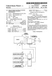
FIG. 1 is a block diagram of a drive system with a jolt
No. 58-77138 to reduce shift shock during a gear shift
control system according to the present invention;
operation by reducing the output torque of the prime
mover during a gear shift operation. This proposal is 20 FIG. 2 is a ?owchart of a program for determining
the number of cylinders to be disabled by fuel-cut oper
intended to reduce the peak of the transmission output
torque during the gear shift operation for shock reduc
ation;
'
FIG. 3 is a diagram illustrating the number of dis
tion by reducing the output torque of the prime mover.
In FIG. 12, a dotted lines curve b shows a waveform of
abled cylinders versus variation in throttle opening
the transmission output torque during the gear shift 25 degree (T R);
operation where the proposal above is applied.
FIG. 4 is a ?owchart of a program for detecting
whether the automatic transmission undergoes a gear
shift operation or not;
FIG. 5 is a diagram used in explaining how to detect
duction, however, a torque drop c occurs due to an 30 a gear shift operation;
additional prime mover torque reduction, inducing an
FIG. 6 is a ?owchart of a program for detecting a
additional shock owing to a difference between the
change in throttle opening degree (TH) during a gear
bottom of this torque drop c and the transmission output
shift operation;
torque obtained after the gear shift operation.
FIG. 7 is a ?owchart of a program for outputting
35
When the accelerator pedal is released to decrease
the throttle opening degree TH, as shown in FIG. 11, in
the course of the torque-down operation for shock re
An object of the present invention is to improve a jolt
demand for fuel-cut;
control system of the above kind such that the occur
FIG. 8 is a ?owchart of a program for deciding the
rence of an additional shock of the above kind is sup
line pressure magnitude in accordance with the amount
by which the prime mover drops the output torque
thereof during a gear shift operation;
FIG. 9 is a graph showing the line pressure character
pressed.
SUMMARY OF THE INVENTION
According to the present invention, there is provided
istic for non-shifting;
_
a jolt control system wherein, during a gear shift opera
FIG. 10 is a graph showing different line pressure
tion, a torque-change control for causing such a tem
characteristics
for different amounts by which the
poral alteration of an engine output torque as to reduce
prime
mover
drops
the output torque thereof during a
45
shift shock is prohibited in response to a change in de
1-2 upshift operation;
pression degree of an accelerator pedal during the gear
FIGS. 11 and 12 are transmission output torque
shift operation.
waveforms used in explaining shocks during a gear shift
According to one aspect of the present invention,
operation.
there is provided a jolt control system for a drive sys
tem including a prime mover provided with manually 50
DETAILED DESCRIPTION OF THE
operable means for controlling output torque of the
INVENTION
prime mover, and an automatic transmission, compris
Hereinafter, the invention will be described in detail
mg:
with reference to the drawings.
sensor means for sensing a position of the manually
operable output torque controlling means and generat 55 FIG. 1 shows one embodiment of a jolt control sys
tem according to the invention, in which 1 denotes an
engine serving as a prime mover and 2 denotes an auto
ing an output signal indicative of said position sensed;
means for e?'ecting an output torque alteration con
matic transmission. The power of the engine 1 is deliv
ered through a torque converter 3 to the automatic
transmission 2, which allows delivery of the power to a
trol, wherein the output torque of the prime mover is
altered, when the automatic transmission undergoes a
gear shift operation; and
means for detecting a predetermined change in said
output signal when the automatic transmission under
goes the gear shift operation and rendering said output
transmission output shaft 4 in a manner to drive the
driving wheels of the vehicle in accordance with a gear
ratio provided by the gear position established in the
automatic transmission.
torque alteration control effecting means inoperable
upon detecting said predetermined change.
According to another aspect of the present invention,
there is provided a jolt control method for a drive sys
tem including a prime mover provided with manually
65
The engine 1 may be an eight-cylinder engine having
eight fuel injection valves 5 for eight cylinders, respec
tively. These fuel injection valves 5 are opened or
closed by an engine control computer 6. The computer
5,016,494
3
4
mined shift pattern table using the throttle opening
degree indicative signal TH (engine load) and the trans
mission output shaft revolution speed indicative signal
NO (vehicle speed) and controls the ON/OFF state of
6 calculates and determines the amount of fuel to be
injected in response to an engine'speed indicative signal
sent from an engine speed sensor 7 which detects the
engine crankshaft revolution speed NE, an engine cool
a throttle opening degree TH representative of . an en
the shift solenoids 11 and 12 to establish the gear posi
tion desired.
Referring to the ?owchart shown in FIG. 2, the func
tion of the circuit or stage 17 is explained. Supplied to
this stage 17 are the signal indicative of the desired shift
gine load. Then, the computer 6 operates to individually
determined at the circuit 16, the throttle opening degree
open each fuel injection valve 5 for a duration of time
which is variable with variation in engine revolution
speed N15 for allowing fuel to be injected to the corre
indicative signal TH from the sensor 9, and a fuel-cut
enabe signal TH from the engine control computer 6. In
FIG. 2, at a step 30, it is determined whether the fuel
cut operation is possible or not by checking whether or
not a fuel-cut enable signal is issued by the engine con
trol computer 6 or not. The engine control computer 6
checks whether or not the engine speed N5 is greater
ant temperature indicative signal from an engine cool
ant temperature sensor 8 which detects a temperature C
of an engine coolant, and a throttle opening degree
indicative signal from a throttle sensor 9 which detects
sponding cylinder of the engine 1. When the output
torque of the engine 1 is reduced while the automatic
transmission 2 undergoes a gear shift operation, a fuel
supply to some cylinder or cylinders is cut to disable the
same.
than or equal to a predetermined value, a coolant tem
The automatic transmission 2 has a control valve
assembly 10. The control valve assembly 10 has a ?rst
shift solenoid 11, a second shift solenoid 12, and a line
pressure solenoid 13. The shift solenoids 11 and 12 are
perature C is higher than or equal to a predetermined
value, and issues the fuel-cut enable signal when condi
tions are met for fuel-cut operation. If it is determined
that the fuel-cut operation is not possible, the number of
cylinders to be disabled (viz., disabled cylinder) is set to
zero at a step 31. If possible, the program proceeds to
rendered ON (energized) and/or OFF (deenergized) or
vice versa in a manner as tabulated in Table l, as fol
lows:
25 steps 32 to 34 to determine which of different types of
TABLE 1
First Speed
Second Speed
Third Speed
Fourth Speed
First Shift
Solenoid ll
Second Shift
Solenoid 12
ON
OFF
OFF
ON
ON
ON
‘OFF
OFF
gear shift the desired shift determined at the stage 16
belongs to. If the desired shift determined at the stage 16
is a downshift or no shift is required, the program pro
30
ceeds through all of the stages 32, 33 and 34 to the step
31 where the number of disabled cylinders is set to 0
(zero) since the engine output reduction control is not
required.
If the desired shift determined is found to be a l-2
In this case, the servo activating hydraulic pressure for
upshift at the step 32, it is determined at steps 35 to 37
35
respective friction elements is a line pressure which is
which of four regions the throttle opening degree TH
generated as a result of pressure regulation under the
falls in. As shown in FIG. 3, these four regions corre
control of the line pressure solenoid 13 that is duty
spond to different numbers of disabled cylinders, re
controlled. During a gear shift operation, the capacity
spectively,
and thus used for evaluating the number of
of a friction element to be hydraulically activated is
disabled
cylinders
for effective reduction of shift shock
controlled by temporarily modulating the line pressure. 40
during the 1-2 upshift operation. If THETHL the num
The on-off control of the solenoids 11, 12 and the
ber of disabled cylinders is set to 4 at a step 38 to allow
the fuel-cut to four cylinders. In the case of
duty control of the line pressure solenoid 13 are exe
cuted by an automatic transmission control computer
TH|>TH;TH2, the number of disabled cylinders is
15. The computer 15 performs various functions which
set
to 2 at a step 39 to allow fuel-cut to two cylinders. If
45
may be illustrated by circuits or stages 16, 17, 18, 19, 20,
TH2>TH§TH3, the number of disabled cylinders is
and 23 for deciding gear position, for deciding number
set to l at a step 40 to allow the fuel-cut to one cylinder.
of disabled cylinders by fuel~cut, for detecting gear
shifting, for outputting demand for fuel-cut, for decid
If TH<TH3, the number of disabled cylinders is set to
0 (zero) at the step 31 to prohibit fuel-cut operation.
ing line pressure, and for detecting return of an acceler
OlA TYPE, SERVICE MANUAL, (A261CO7)” issued
If the desired shift determined at the stage 16 is found
to be a 2—3 upshift at the step 32 or a 3-4 upshift at the
step 34, a similar control to the control enclosed by a
block 41 is executed at a step 42 or 43, although TH1,
TH; and TH3 are set to different values. As is now be
(Hayasaki et al.) which is hereby incorporated in its
entirety‘ by reference.
Referring to FIG. 4, the function of detecting gear
shift operation performed at the stage 18 is explained.
drawn by broken lines, the flowcharts shown in FIGS.
2, 4, 6, 7, and 8 are explained although these programs
lution speed N0 and the desired shift determined at the
stage 16. In FIG. 4, at a step 50, an apparent gear ratio
ator, respectively.
The automatic transmission mentioned above is of the
RE4R01A type described in “NISSAN FULL
RANGE AUTOMATIC TRANSMISSION RE4R
50
on Mar. 1987 by NISSAN MOTOR COMPANY LIM 55 appreciated, the different numbers of disabled cylinders
are set for different types of shift operations in order to
ITED. The automatic transmission of the above men
effectively reduce the shift shock, respectively.
tioned type is also disclosed in US. Pat. No. 4,680,992
In order to make clear the functions attributed to the 60 Supplied to this stage 18 are the transmission input shaft
revolution speed N1, the transmission output shaft revo
circuits or stages shown in FIG. 1 enclosed by block
Nr/No is calculated. Then, the type which the desired
are stored in a read only memory (ROM) of the auto
matic transmission control computer 15 and executed 65 shift determined at the stage 16 belongs to is evaluated
at steps 51 to 53. If the desired shift determined at the
under the control of a central processing unit (CPU).
stage 16 is found to be a downshift or no shift is re
At the circuit or stage 16, a desired shift operation in
quired, it is unnecessary to reduce the engine output
gear position is determined by looking up a predeter
5
5,016,494
6
during the shift operation. Thus, a flag F1 indicating
the accelerator pedal is released during the gear shift
that the shift operation is under progress is reset to 0'
(zero). If the desired shift is any one of a 1-2 upshift, a
2-3 upshift, or a 3-4 upshift, the gear ratio G is checked
course of an upshift operation, or the fuelcut cylinder
number is zero, then the program proceeds from ~the
operation, or the automatic transmission is not in the
corresponding one of steps 55, 56, and 57 to determine
whether or not the upshift operation progresses. Refer
ence should be made to FIG. 5 in this regard. If it is
step 78, 70 or 71 to the step 72 where no command is
produced to the computer 6 so that the engine operates
on all cylinders. If the fuelcut cylinder number is I, then
the program proceeds from the step 73 to the step 74
where a command is produced to cause the computer 6
to terminate the fuel delivery to one cylinder. If the
determined that the upshift operation is under progress,
fuelcut cylinder number is 2, then the program proceeds
in comparison with predetermined. values 38 and 4L in
the case of 3-4 upshift, 2S and 3L in the case of 2-3
upshift, and 1S and 2L in the case of l-2 upshift, at the
to the step 75 to the step 76 where a command is pro
the flag F1 is set to l at the corresponding step 58 or 59
or 60. If it is found that the upshift operation is not yet
duced to cause the computer 6 to terminate the fuel
initiated or completed, the flag F1 is reset to zero at the
delivery to two cylinders. If the fuelcut cylinder num
15 ber is 4, then the program proceeds from the step 75 to
corresponding step 54 or 61.
The function of the accelerator pedal return detect
the step 77 where a command is produced, causing the
ing circuit or stage 23 shown in FIG. 1 is now explained
computer 6 to terminate the fuel delivery to four cylin
along with the ?owchart shown in FIG. 6.
ders. The computer 6 responds to one of such com
Referring to FIG. 6, the function of this stage 23 to
mands by closing fuel injectors to terminatethe fuel
detect whether or not the accelerator pedal has been 20 delivery to the corresponding cylinders so as to reduce
returnedis explained. Supplied to this stage 23 are the
throttle opening degree TH fed thereto from the sensor
9 and the desired shift fed thereto from the stage 16. In
the engine output torque during the upshift operation.
Referring to FIG. 8, the function to deciding the
magnitude or level of the line pressure (servo activating
FIG. 6, at the step 62, a determination is made as to
hydraulic ?uid pressure) performed at the stage or cir
whether or not the automatic transmission undergoes a 25 cuit 20 is explained. At the stage 20, the driving duty of
gear shift operation. If the answer to this question is
the line pressure solenoid 13 is determined. Supplied to
“yes”, then the program proceeds to the steps 63a~63c
the stage 20 are the desired shift indicative signal from
where the throttle opening degree TH is set as a value
the stage 16, the throttle opening degree, indicative
THO for the initiation of the gear shift operation, the
signal TH and the signal indicative of the number of
value is stored in the memory, and a flag F10 is set to 1
indicating that the value is stored in the memory. Fol
lowing this the program proceeds from the step 630 to
640.
At the steps 64a-64c, a determination is made as to
disabled cylinders used in the stage 19. In FIG. 8, at a
step 80, it is determined whether the automatic trans
mission 2 is under upshifting or not by checking the
gear ratio G. If the transmission is not under shifting,
the program proceeds to a step 81 where a table look-up
whether or not the throttle opening degree TH is equal 35 operation of the characteristic PN shown in FIG. 9 is
to or less than the value THO minus a predetermined
value 0. (alpha) or whether the accelerator pedal is
released during the gear shift operation. If the accelera
tor pedal is released during the gear shift operation,
then a flag F11 is set to 1. It is to be noted that these
operations are performed only once when the accelera
tor pedal is released during the gear shift operation and,
conducted using the throttle opening degree TH to
retrieve a line pressure data in terms of duty factor to be
supplied to the line pressure solenoid 13. If it is deter
mined at the step 80 which one of the three types of
upshifting operations, namely a l-2 upshift, a 2-3 up
shift and a 3-4 upshift, is under progress, the program
proceeds toward steps 82, 83, and 84 where the type of
thereafter, the steps 64b and 640 are jumped so that the
the shifting now under progress is checked. If it is deter
flag F11 remaines at 1.
mined at the step 82 that the I-2 upshift is under
If the automatic transmission is not in the course of a 45
gear shift operation, then the program proceeds from
the step 62 to the step 65 where the flag F10 is cleared
to 0 and then to the step 66 where the flag F11 is cleared
to 0.
progress, the program proceeds toward the steps 85, 86
and 87 where the number of disabled cylinders is
checked. If the number of disabled cylinders is 0 (zero),
the program proceeds down to a step 88 where a table
Referring to FIG. 7, the function to output demand 50 look-up operation of the line pressure characteristic P0
shown in FIG. 10 is conducted using the throttle open
for fuel-cut operation performed at the circuit or stage
ing
degree TH to retrieve an appropriate line pressure
19 is explained. The demand for fuel-cut operation is fed
data in terms of a duty factor to the line pressure sole
to the engine control computer 6 to cut fuel supply to
noid 13. If it is determined at the step 85 that the number
some of the cylinders of the engine 1 thereby to urge the
engine 1 to reduce output torque thereof. Supplied to 55 of disabled cylinder is l, the program proceeds to a step
89 where a table look-up operation of the line pressure
the stage 19 are a signal indicative of the status of the
characteristic P1 shown in FIG. 9 is performed using the
flag F11 fed thereto from the stage 23, a signal indica
throttle opening degree TH to retrieve an appropriate
tive of the status of the ?ag F1 fed thereto from the
data in terms of duty factor to the line pressure solenoid
stage 18 and a signal indicative of the number of dis
13. If it is determined that the number of disabled cylin
abled cylinders set at the stage 17. In FIG. 7, at the step
78, a determination is made as to whether or not F11 =1
ders is 2 at the step 86 or 4 at the step 87, a table look-up
the gear shift operation. If the answer to this question in
“no”, then the program proceeds to another determina
operation of the corresponding line pressure character
istic P2 or P4 shown in FIG. 9 is preformed using the
throttle opening degree TH to retrieve an appropriate
F1=l indicating that the automatic transmission is in
the course of an upshift operation during which an
13. Thus, the line pressure solenoid 12 is operated on the
duty factor determined at the step 81, 88, 89, 91, or 92 to
indication that the acclerator pedal is released during
tion step 70. This determination is as to whether or not 65 data in terms of duty factor to the line pressure solenoid
engine output reduction is required to reduce shocks. If
bring the magnitude of the line pressure into agreement
7
5,016,494
with the corresponding one of the line pressure charac
teristics.
In such a manner, the line pressure control is per
formed according to the number of the disabled cylin
ders (engine output torque reduction) during the 1-2
upshift operation. It is, therefore, possible to control the
capacity of the friction element operated during the
5
8
said output torque alteration control effecting
means inoperable upon detecting said predeter
mined change, whereby the automatic transmission
undergoes the gear shift operation without the
output torque alteration control.
2. A jolt control system as claimed in claim 1,
wherein said output torque alteration control includes a
gear shift operation according to the output torque and
to reduce shock during the l-2 upshift operation by the
engine output torque reduction and the corresponding
friction element capacity control. Since the capacity
control corresponds to the torque reduction, it is possi
torque-down control, wherein the output torque of the
prime mover is reduced, when the automatic transmis
sion undergoes an upshift operation.
3. A jolt control system as claimed in claim 1,
wherein said sensor means include means for detecting
ble to ensure shock reduction during the gear shift oper
a throttle opening degree of a throttle valve of the
ation and prevent the friction element from being dam
prime mover operatively connected to the accelerator.
aged due to an insufficient friction element capacity. 15
4. A jolt control system as claimed in claim 1,
If the desired gear shift operation is a 2—3 upshift or a
wherein said means for detecting said predetermined
3-4 upshift, then the program of FIG. 8 proceeds from
change in said output signal include a predetermined
the steps 83 or 84 to the steps in the block 93 or 94
indicator which is set upon detecting said predeter
which are substantially the same as the steps in the
block 92 except for the line pressure characteristic 20
mined change.
5. In a drive system including a prime mover pro
curves. In such a manner, it is possible to reduce shocks
vided with manually operable means for controlling
during the 2-3 or 3-4 upshift operation like the l-2
output torque of the prime mover, and an automatic
upshift operation.
transmission, the automatic transmission undergoing a
If the desired gear shift operation is a downshift, then
gear shift operation, a jolt control method for the auto
the program proceeds from the step 84 to the step 95 25 matic transmission when the automatic transmission
where an appropriate line pressure characteristic curve
undergoes the gear shift operation comprising the steps
is selected according to the kind of the downshift opera
of:
tion. An appropriate value of the duty ratio for the
sensing a position of the manually operable output
solenoid 13 is calculated from the selected line pressure
torque controlling means and generating an output
30
characteristic curve which de?nes it as a function of
signal indicative of said position sensed;
throttle position and the calculated duty ratio value is
transferred to control the solenoid 13.
If the accelerator pedal is returned during the gear
shift operation, then the program of FIG. 7 proceeds
from the step 78 to the step 72 where the engine output 35
torque reduction control is inhibited. If the engine out
put reduction control is continued in spite of the fact
that the engine output torque decreased due to return of
the acceleration pedal during the gear shift operation, a
torque reduction c will occur, as described previously 40
in connection with FIG. 11, causing an additional shock
during the gear shift operation. Since such a torque
reduction control is inhibited, it is possible to avoid such
a problem.
What is claimed is:
1. In a drive system including a prime mover pro
vided with manually operable means for controlling
output torque of the prime mover, and an automatic
transmission, the automatic transmission undergoing a
gear shift operation, a jolt control system for the auto 50
matic transmission when the automatic transmission
undergoes the gear shift operation, comprising:
effecting an output torque alteration control, wherein
the output torque of the prime mover is altered,
when the automatic transmission undergoes the
gear shift operation;
detecting a predetermined change in said output sig
nal when the automatic transmission undergoes the
gear shift operation; and
rendering said output torque alteration control inop
erable upon detecting said predetermined change,
whereby the automatic transmission undergoes the
gear shift operation without the torque alteration
control.
6. In a vehicle engine drive system provided with
manually operable means for controlling the output
torque of the' engine and an automatic transmission, a
jolt control system for the automatic transmission when
the automatic transmission undergoes a gear shifting
operation, comprising:
?rst sensor means for detecting a change in engine
torque as a result of a gear shifting operation;
second sensor means for detecting the throttle open
ing position of the engine;
sensor means for sensing a position of the manually
operable output torque controlling means and gen
erating an output signal indicative of said position 55
third sensor means for detecting engine performance
parameters, including engine speed and tempera
ture; and a central processing unit for receiving the
outputs of the ?rst, second and third sensors and
sensed;
means for effecting an output torque alteration con
generating signals to control the supply of fuel to
trol, wherein the output torque of the prime mover
is altered, when the automatic transmission under
goes the gear shift operation: and
means for detecting a predetermined change in said
each cylinder so as to eliminate jolt from manual
gear shifting under high engine torque conditions,
the central processing unit cutting off the supply of
fuel to selected cylinders of the engine.
output signal when the automatic transmission
undergoes the gear shift operation and rendering
it
65
i
l!
*
i