1
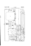
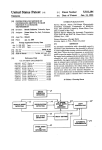
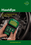
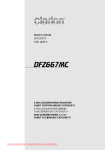
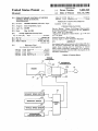
llllllllllllllIIIIllllllllllllllIllllllllllllllllllllllllllllllllllllllllll
.
USOO5088348A
United States Patent [19]
[11] Patent Number:
Hiramuki
[45]
[54]
EXHAUST BRAKE CONTROL OF MOTOR
4,966,110 10/1990 Seki et al. ..................... .. 123/321 X
VEHICLE WITH AUTOMATIC
4,996,893
TRANSMISSION
Inventor:
_
Shizuoka, Japan
_
_
_
Type”, (A267lC07) (no date).
“Automotive Engineer’s Hand Book”, pp‘ 6-46 and
Japan .............................. .. 63-22880?
6-47 (no date).
Int. Cl.5 ....................................... .. F02D 9/06
U.S. Cl. ............ ..
74/859; 123/322
Field of Search ....................... .. 74/859, 860, 878;
123/321, 322
Primary Examiner—Dirk Wright
Attorney, Agent, or Firm-Ronald P. Kananen
TR lCr
[57]
ABS
_
_
[56]
Nakamura et a1. ................. .. 74/866
OTHER PUBLICATIONS
Service Manual “Nissan Full-Range Electronically
Controlled Automatic Transmission E-AT, RE4R01A
Forms" Applmmon Pnomy Data
Sep. 14, 1988 [JP]
[51]
[52]
[58]
_
3/ 1991
Feb. 18, 1992
FOREIGN PATENT DOCUMENTS
Japan _
[73] Assignee: Jatco Corporation, Japan
[21] Appl' No" 669,889
[22] Filed;
Man 14, 1991
[30]
Date of Patent:
5,088,348
An exhaust brake control ensures a shock less shift after
References C'ted
U.S. PATENT DOCUMENTS
the automatic transmission has been conditioned for
engine brake running state by rendering an exhaust
2,393,579 1/1946 Weiss et al. ....................... .. 123/322
3 710 908
mm Muir
4,188,933
4,680,992
4,742,806
2/1980 Iizuka ............... ..
7/1987 Hayasaki et a]. ..
5/1988 Tart, Jr. et a1. ................... .. 123/322
brf‘ke syslem mepmblc tempc’ianiy. f°r a pre‘lete"
...................... .. 74/878 x
mmed Penod of “me when the Sh‘f‘ ‘5 1“ progress 1“ the
automatic transmission
'
7 Claims, 3 Drawing Sheets
TORQUE
CONVERTER
l0
/
/2 AUTOMATIC
lgl ,Za / TRANSMISSION
I
ENGINE
I?!)
\
\
\
p
.___.
|
I
/4/
L"
20
/e
22
./
EXHAUST BRAKE SWITCH
/a
/
/24
INHIBITOR SWITCH
/2e
VEHICLE SPEED SENSOR
28
ACCELERATOR
POSITION SENSOR
CONTROL
UNIT
/3
U.S. Patent
Feb. 18, 1992
Sheet 1 of 3
5,088,348
FIG . 1 '
TORQUE
CONVERTER ,7
l0
/
H
W
/2 AUTOMATIC
; Q0 /TRANSMISSION
ENGINE
fl. \\
II ' I ‘,_
4
.
\\ i; ,I
/ r1
/4 /
“
A
\“20
/6
22
/8
/ I
l/
EXHAUST BRAKE SWITCH
/ 24
INHIBITOR SWITCH
CONTROL
UNIT
VEHICLE SPEED SENSOR
/%
ACCELERATOR
POSITION SENSOR
*
.
US. Patent
8 Feb. 18, 1992
Sheet 2 of 3
FIG-2
IS
COMMAND FOR
NO
ENGINE BRAKE
AVAILABLE
IO/
IS
COMMAND FOR
3-2 DOWNSHIFT
AVIL'PABLE
‘
YES
RESET T = 0
//O2
/
/04
RENDER EXHAUST
BRAKE INOPERABLE
RENDER EXHAUST
BRAKE OPERABLE “J08
FIG- 3
( START )
T=T+1
( RETURN )
5,088,348
US. Patent
Feb. 18, 1992
Sheet 3 of 3
. FIG . 4
/OO
IS
CONNABD FOR
ENGINE BRAKE
AVAILABLE
S
COMMAND FOR
3-2 DOWNSHIFT
AVILgBLE
/02
RESET T = 0 /
/04
RENDER EXHAUST
BRAKE INOPERABLE
200
READ VEHICLE
SPEED v
i
202
SET T1 = mv)
T>T1 ?
YES
"0
/06
RENDER EXHAUST //08
BRAKE OPERABLE
END
5,088,348
1
5,088,348
2
FIG. 3 is a flow diagram of a timer program stored in
EXHAUST BRAKE CONTROL OF MOTOR
VEHICLE WITH AUTOMATIC TRANSMISSION
BACKGROUND OF THE INVENTION
The present invention relates to a motor vehicle in
cluding an automatic transmission and an engine with
an exhaust brake system, and more particularly to a
control of such an exhaust brake system.
A known automatic transmission has a manual selec
tor lever having a D range and a 2 range. When the 2
the control unit; and
FIG. 4 is a flow diagram of a modi?cation of the
program shown in FIG. 2.
DETAILED DESCRIPTION OF THE
INVENTION
Referring to FIG. 1, a motor vehicle is shown in a
block diagram which includes an engine 10 and an auto
matic transmission 12. The automatic transmission 12 is
of the well known RE4ROlA type and described in a
service manual “NISSAN FULL-RANGE ELEC
range is selected by the manual selector lever, the auto
TRONICALLY CONTROLLED AUTOMATIC
matic transmission is conditioned in engine brake run
TRANSMISSION E-AT,
RE4ROlA TYPE”
ning state where a direct motion connection is estab 15 (A261C07) which was issued by Nissan Motor Co., Ltd.
lished between the transmission input and output shafts.
in March, 1987. This publication is hereby incorporated
If, under this condition, an exhaust brake switch is
turned on, an exhaust brake system becomes in opera
tion to cause activation of exhaust brake. With the auto
by reference in its entirety. The automatic transmission '
matic transmission in the engine brake running state and
the exhaust brake activated, if the vehicle speed drops
pump impeller is coupled with the engine 10. An output
down to a vehicle speed value at which the automatic
transmission effects a downshift, a great shift shock
cannot be avoided. The present invention aims at allevi
ating this problem.
SUMMARY OF THE INVENTION
12 has an input shaft 120, i.e., a turbine shaft, coupled
with a turbine runner of a torque converter 11 whose
shaft 12b of the automatic transmission is drivingly
connected to driving wheels, only one of which being
shown at 13.
For increased engine braking, the engine 10 is
25 equipped with an exhaust brake system 14. A typical
example of such an exhaust brake system is described on
pages 6-46 and 6-47 of “AUTOMOTIVE ENGIN
NER’S HAND BOOK” published by Society of Auto
motive Enginners of Japan. Briefly, the exhaust brake
engine brake running state by rendering an exhaust 30 system 14 is constituted by a valve arranged for closing
the engine exhaust system and a cooperating valve ar
brake system inoperable temporarily for a predeter
ranged in the engine intake system, means including a
mined period of time when the shift is in progress in the
The present invention ensures a shock less shift after
the automatic transmission has been conditioned for
automatic transmission.
According to the present invention, a motor vehicle
having an automatic transmission and an exhaust brake
system is provided with:
means for generating a command for engine brake
running state; and
means for rendering the exhaust brake system inoper
able temporarily for a predetermined period of time
when a predetermined shift is in progress in the auto
matic transmission after said command has been gener
ated.
According to one embodiment, the predetermined
period of time is variable with the vehicle speed.
According to another aspect of the present invention,
there is provided a method of exhaust brake control in
a motor vehicle having an engine and an automatic
transmission, the automatic transmission having an
input shaft and an output shaft and being shiftable to an
engine‘ brake running state wherein a direct motion
solenoid 16 for closing the valve in the exhaust system
in response to energization of the solenoid 16, and a
manually operable exhaust brake switch 22 disposed
near a driver’s seat. According to the known control
strategy, releasing an accelerator pedal after the exhaust
brake switch 22 has been turned on causes energization
of the solenoid 16, causing activation of exhaust brake.
The automatic transmission 12 has a hydraulic con
trol valve assembly 20. The control valve assembly 20
has a plurality of solenoids including shift solenoids and
a line pressure solenoid. The solenoid 16 of the exhaust
brake system 14, and the plurality of solenoids of the
control valve assembly 20 are operatively connected to
a microcomputer based control unit 18.
Supplied to the control unit 18 are signals generated
by the exhaust brake switch 22, a select position detect
ing switch, i.e., an inhibitor switch 24, a vehicle speed
sensor 26, and an accelerator position sensor 28 in the
form of a throttle opening degree sensor if the engine
has a throttle which opens in degrees. If the engine 10 is
connection is established between the input and output
a diesel engine which is not provided with a throttle
shafts, the motor vehicle also having an exhaust brake
valve, the accelerator position sensor 28 directly mea
system, the method comprising the steps of:
55 sures the position or depressing degree of the accelera
generating a command for the engine brake running
state; and
rendering the exhaust brake system inoperable tem
porarily for a predetermined period of time when a
predetermined shift is in progress after said command
has been generated.
tor pedal. The selector lever has a N (neutral) range, a
D (drive) range, and a 2 range. When the manual selec
tor lever is placed at the 2 range or a power shift switch
is set at “POWER” position with the manual selector
lever at D range, the automatic transmission 12 is shift
able to an engine brake running state where a direct
motion connection is established between the input and
output shafts 12a and 12b. The inhibitor switch 24 de
FIG. 1 is a block diagram of a motor vehicle with an
tects which one of the plurality of positions the manual
exhaust brake system control according to the present 65 selector lever is placed at. The vehicle speed sensor 26
detects a revolution speed of the transmission output
invention;
shaft 12b and thus a vehicle speed of the motor vehicle
FIG. 2 is a flow diagram of a program stored in a
and generates a vehicle speed indicative signal indica
control unit shown in FIG. 1;
BRIEF DESCRIPTION OF THE DRAWINGS
3
5,088,348
tive of the vehicle speed. The accelerator position sen
sor 28 detects an opening degree of the engine throttle
or a depression degree of the accelerator pedal and
generates an accelerator depression degree indicative
4
Referring to FIG. 2, in a step 100, it is determined
whether or not there is a command for engine brake
running state by checking the output signal of the inhib
itor switch 24 or checking the state of the power shift
signal indicative of the throttle opening degree or the
switch. The inquiry in this step 100 results in affirmative
accelerator depression degree detected.
With the manual selector lever placed at D range, the
when the manual selector lever is set to 2 range or the
power shift switch is set to “POWER” position with the
manual selector lever set to D range. Otherwise, the
control unit 18 reads output signals of the vehicle speed
inquiry results in negative. If the inquiry of this step 100
sensor 26 and accelerator position sensor 28 and deter
results in negative, the execution of this program ends.
If it results in affirmative, the program proceeds to a
step 101 where it is determined whether or not there is
a command o4 requirement for a 3-2 downshift. If the
Operation of this embodiment is as follows:
mines a desired or target speed ratio after retrieving a
predetermined shift point mapping based on the output
signals. In accordance with the output signals of the
control unit 18 supplied to the shift solenoids of the
inquiry of this step 101 results in negative, the execution
control valve assembly 20, the automatic transmission a 5 of this program ends. If this inquiry results in affirma
12 automatically shifts among the ?rst, second, third
tive, the program proceeds to a step 102 where a timer
and fourth speed ratio when the manual selector lever is
T is reset to 0 (zero), and then to a step 104 where the
placed at D range. Let us now assume that the vehicle
travels with the third speed ratio established in the
exhaust brake is rendered inoperable even if the exhaust
brake switch 22 is turned on by suspending electric
automatic transmission 12. If the driver turns on the
exhaust brake switch 22 and releases the accelerator
pedal, the solenoid 16 of the exhaust brake system 14 is
current passing through the solenoid 16. After suspend
ing the supply of electric current supplied to the sole
noid 16, the program proceeds to a step 106 where it is
energized. Subsequently, under this condition, if the
determined whether or not the timer T is greater than a
automatic transmission 12 shifts to the engine brake
predetermined period of time T1. The time T is incre
running state, strong engine brake is accomplished.
In this automatic transmission 12, the engine brake
running state is established when an overrunning clutch
is engaged. This overrunning clutch is engaged when
mented in a step 110 upon executing a program of FIG.
3 upon elapse of a predetermined period of time. Refer
ring back to FIG. 2, the step 106 is repeated as long as
the timer T is not greater than T1. Upon elapse of the
predetermined period of time T1 after the command for
the vehicle speed drops to a predetermined value with 30
the accelerator pedal released after the power shift
3-2 downshift has occurred, the timer T becomes
switch has been set to a “POWER” position for select
greater than T1, and the inquiry of the step 106 results in
ing a power shift pattern with the manual selector lever
affirmative. Thus, the program proceeds to a step 108
placed at D range of after the manual selector lever has
where the exhaust brake is rendered operable to allow
been moved from D range to 2 range. For further infor (A) 5 supply of electric current to the solenoid 16 if the ex
mation, reference should be made to pages I-30 to I-32
haust brake switch 22 is left turned on. The setting of
of the before-mentioned service manual “NISSAN
the predetermined period of time T1 is such that the 3-2
FULL-RANGE
ELECTRONICALLY
CON
downshift is completed prior to elapse of this period of
TROLLED AUTOMATIC TRANSMISSION E-AT,
time.
RE4RO1A TYPE” (A261C07). For operation and con
trol of the overrunning clutch of this automatic trans
mission, reference should be made to US. Pat. No.
4,680,992 issued to Hayasaki et al. on Jul. 21, 1987,
It will now be appreciated that since the activation of
exhaust brake is suspended while a predetermined shift
is in progress in the automatic transmission after a com
which is hereby incorporated by reference in its en
tirety.
-
As the vehicle speed drops down to a vehicle speed
value at which a predetermined shift, for example a 3-2
downshift, is to take place. The control unit 18 deter
mines that a command for the 3-2 downshift is available
45
mand for engine brake running state has become avail
able, the automatic transmission effects the predeter
mined shift without substantial shock. Upon completion
of the shift, strong engine brake is provided.
Since a period of time required for a shift is depen
dent on vehicle speed, it is desired to vary the above
mentioned predetermined period of time in proportion
upon making a judgement that the target speed ratio is 50 to varying vehicle speed. This can be accomplished by
the second speed ratio and the actual speed ratio re
slightly modifying the program of FIG. 2. FIG. 4 shows
mains the third speed ratio. Then, the control unit 18
such a modi?cation.
renders exhaust brake inoperable by suspending electric
Referring to FIG. 4, this program is different from
current supplied to the solenoid 16 for a predetermined
the program of FIG. 2 in the provision of two steps 200
period of time beginning with the command for the 3-2 55 and 202 between the steps 102 and 106. In the step 200,
downshift. The setting of the predetermined period of
a reading operation is performed on the output signal of
time is such that the exhaust brake is inoperable while
the vehicle speed sensor 26 to store the result as a vehi
the 3-2 downshift is in progress in the automatic trans
cle speed V. In the subsequent step 202, the predeter
mission 12. Upon elapse of the predetermined period of
mined period of time T1 is set as a function of the vehi
time, the control unit 18 allows the exhaust brake to 60 cle speed V stored in the previous step 200.
become operable again so that the supply of electric
What is claimed is:
current to the solenoid resumes if the exhaust brake
1. In a motor vehicle having an engine and an auto
switch 22 is left turned on. Thus, strong engine brake
matic transmission, the automatic transmission having
becomes effective again upon completion of the 3-2
an input shaft and an output shaft and being shiftable to
downshift.
65 an engine brake running state wherein a direct motion
The control unit 18 stores a program as illustrated in
connection is established between the input and output
FIG. 2 and executes the program to perform the opera
tion described above.
shafts, the motor vehicle also having an exhaust brake
system:
5
5,088,348
6
5. A method of exhaust brake control in a motor
means for generating a command for the engine brake
vehicle having an engine and an automatic transmission,
the automatic transmission having an input shaft and an
output shaft and being shiftable to an engine brake run
ning state wherein a direct motion connection is estab
running state; and
means for rendering the exhaust brake system inoper
able temporarily for a_ predetermined period of
time when a predetermined shift is in progress in
the automatic transmission after said command has
lished between the input and output shafts, the motor
vehicle also having an exhaust brake system, the
been generated.
method comprising the steps of:
generating a command for the engine brake running
state; and
rendering the exhaust brake system inoperable tem
2. A motor vehicle as claimed in claim 1, further
comprising:
means for detecting a vehicle speed of the motor
vehicle and generating a vehicle speed indicative
signal indicative of said vehicle speed detected.
3. A motor vehicle as claimed in claim 2, wherein said
' porarily for a predetermined period of time when a
predetermined shift is in progress after said com
mand has been generated.
predetermined period of time is variable with said vehi
6. A method as claimed in claim 5, wherein said pre
determined period of time is variable with a vehicle
speed of the motor vehicle.
cle speed indicative signal.
4. In a motor vehicle having an engine and an auto
matic transmission, the automatic transmission having
7. A method of exhaust brake control in a motor
an input shaft and an output shaft and being shiftable to
an engine brake running state wherein a direct motion
vehicle having an engine and an automatic transmission,
the automatic transmission having an input shaft and an
connection is established between the input and output
output shaft and being shiftable to an engine brake run
shafts, the motor vehicle‘also having an exhaust brake
ning state wherein a direct motion connection is estab
system:
lished between the input and output shafts, the motor
means for generating a command for the engine brake
vehicle also having an exhaust brake system, the
running state;
25 method comprising the steps of:
means for detecting a vehicle speed of the motor
generating a command for the engine brake running
vehicle and generating a vehicle speed indicative
signal indicative of said vehicle speed detected; and
state;
determining whether or not there is a command for a
means for setting a predetermined period of time
variable with said vehicle speed indicative signal
predetermined shift in the automatic transmission;
and
and rendering the exhaust brake system inoperable
rendering the exhaust brake system inoperable for a
temporarily for said predetermined period of time
predetermined period of time when said predeter
when a predetermined shift is in progress in the
automatic transmission after said command has
mined shift is in progress after said command for
the engine brake running state has been generated.
been generated.
35
45
50
55
65
#
i
‘
*
i