1
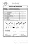
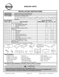
GENUINE PARTS
INSTALLATION INSTRUCTIONS
1.
2.
DESCRIPTION:
APPLICATION:
PART NUMBER:
3.
LED Daytime Driving Lights
ALTIMA SEDAN / COUPE
(2010 w/o Foglamp)
B66M0 JA00B
Installation of this accessory requires installation of additional Nissan
Genuine Part(s):
●for Sedan without foglamps:
●Fog Lamp Bracket LH / RH (26916 ZX00A / 26911 ZX00A)
●for Coupe without foglamps:
●Bumper Finisher LH / RH (62257 ZX10B / 62256 ZX10B)
4.
KIT CONTENTS:
Item
A
B
C
D
E
F
G
H
I
J
K
L
M
N
O
QTY
1
1
2
1
1
1
17
6
8
1
8
2
4
4
1
A
Description
B
F
K
5.
Service Part Number
Lamp Module RH
Lamp Module LH
Control Unit
Accessory Engine Room Harness
Accessory Main Harness
Accessory Jumper Harness
Tie Wrap (L=150mm)
Tie Wrap (L=200mm)
Double Sided Tape
Butyl Tape
Urethane Foam Tape
Spacer
Nut
Bolt
Installation Instructions
C
G
L
TOOLS REQUIRED:
● Nylon removal tool
● Phillips screw driver
● Scissors
● Soft non linting towel
B6600 JA001
B6600 JA002
D
E
I
H
M
O
N
● Wire cutter
● Masking tape
● 100% alcohol
● Awl
J
● 10mm Socket, 21mm Deep Socket and driver
● Flash light
● Soap water
Page 1 of 21
B66M0 JA00B II REV 12/15/2009
INSTALLATION INSTRUCTIONS - LED Daytime Driving Lights
6.
PRE-INSTALLATION CAUTIONS/NOTES
CAUTION
● Dealer Installation Recommended. Instructions refer to Service Manual.
● Please read this instruction carefully before installing this product for correct installation.
● Please DO NOT use or install the part in ways other than what is described in this instruction
manual.
● If problem occurs during installation, please contact Nissan dealer where you purchased the
product.
● Pay attention when removing trim parts to avoid breaking clips.
1) Apply Parking Brake.
2) Make sure the shift lever is engaged in"P"or"N"position.
Preset
1
3) Record customer Radio Presets.
A
B
4) Use seat and floor protection.
C
5) Open the hood of the vehicle.
2
3
4
5
6
6) Disconnect the negative battery terminal to prevent short circuits during installation.
7) This part is to be installed at a vehicle body surface temperature of 65-100°F.
8) Do not wash the vehicle for 24 hours after installing to prevent the double-sided tape from peeling.
CAUTION
● Care must be taken not to scratch or damage any components during the removal or
replacement process.
9) Remove the following vehicle parts in the sequence shown below.
5
1.
2.
3.
4.
5.
Tire and wheel
Front bmpr
Fender protector (front) LH
Fender protector (rear) LH
USM module cover
3
4
2
1
10
14
12
6
11
9
15
7
8
6. Instrument side mask (LH)
7. Instrument lower cover (LH)
8. Kicking LH
9. Dashboard side lower panel
10. Cluster lid D
11. Console finisher
12. Storage bin or CD changer
13. Instrument side panel LH
14. Instrument side panel RH
15. Center console assembly
13
Page 2 of 21
B66M0 JA00B II REV 12/15/2009
INSTALLATION INSTRUCTIONS - LED Daytime Driving Lights
7.
INSTALLATION OUTLINE
Hand Parking
Brake Models
Foot Parking
Brake Models
8.
STANDARD CONNECTION METHOD
USM
NS08FW TH16FW
ILL 0.5 (Lg/R)
IGN 0.5 (R/W)
Control
unit
Lamp
module
Control
unit
Lamp
module
NS08MW TH16MW
Connector of
vehicle USM
NS08MW
NS08F
Parking
Parking
brake
brake
P01FB
PKB 0.5 (W/B)
GND 0.5 (B)
FEM
+B 0.5 (Sb)
P01MB
Connector of vehicle
Parking brake
Page 3 of 21
B66M0 JA00B II REV 12/15/2009
INSTALLATION INSTRUCTIONS - LED Daytime Driving Lights
9.
VEHICLE PARTS REMOVAL
Fender
Fig 1
1) Apply protective tape to front fender and bumper
(LH/RH) as shown in Fig 1.
Fig 2
2) Remove clips (6) from top surface of bumper as
shown in Fig 2.
Fig 3
3) Remove wheel and tire (LH) as shown in Fig 3.
Fig 4
4) Remove screws (6) and clips (5) from bottom of
bumper as shown in Fig 4.
Tape
Front bumper
Clips (6)
Tire (LH)
Front bumper
Screws
(3)
(5)
Clips
Screws(3)
A
View A
Screws(3)
Screws(3)
Clips(5)
Page 4 of 21
B66M0 JA00B II REV 12/15/2009
INSTALLATION INSTRUCTIONS - LED Daytime Driving Lights
9.
VEHICLE PARTS REMOVAL CONT'D
Fig 5
5) Remove clips (9) and screws (2) from front fender
protector (front/rear) LH as shown in Fig 5.
Clips
(4)
Screws
(2)
Clips
(5)
FR
Fig 6
Front bumper
Front bumper side bracket
6) Remove bolt (LH/RH) holding front bumper to
front fender as shown in Fig 6.
Bolt
Fig 7
7) Pull out on upper corners of front bumper to
disengage from side bracket as shown in Fig 7 and
remove front bumper.
Pawl
CAUTION
● Take care to not damage the pawls on the
Front bumper
front bumper and side bracket.
Fig 8
8) Remove energy absorber from bumper
reinforcement as shown in Fig 8.
Energy absorber
Page 5 of 21
B66M0 JA00B II REV 12/15/2009
INSTALLATION INSTRUCTIONS - LED Daytime Driving Lights
9.
VEHICLE PARTS REMOVAL CONT'D
(2) Pawls
Fig 9
9) Remove USM module cover by pushing pawls (2)
at locations shown in Fig 9 and pulling up on
cover.
Fig 10
10) Remove USM module harness cover by pushing
pawls (2) at locations shown in Fig 10 and pulling
up on cover.
(2)
Pawls
Page 6 of 21
B66M0 JA00B II REV 12/15/2009
INSTALLATION INSTRUCTIONS - LED Daytime Driving Lights
9.
VEHICLE PARTS REMOVAL CONT'D
Fig 11
Nylon
removal
tool
Instrument
side mask (LH)
Fig 12
Screw
CVT models only
Fig 13
c) Control lever knob
b) Lock pin
a) Knob cover
b)
Use nylon removal tool to detach pawls/clips
and remove instrument side mask (LH).
12) Remove instrument lower cover as shown in Fig
12.
a)
Open fuse block cover and remove instrument
lower cover screw.
b)
Pull downward at pawl locations to disengage
pawls and clips.
c)
Pull back instrument lower cover and
disconnect harness connector/clips.
13) (For Hand Parking Brake Models Only)
Remove control device selector plate as shown in
Fig 13.
a)
Put selector lever in drive (D) position and
pull downward on knob cover.
b)
c)
d)
Remove lock pin.
Pull up to remove control lever knob.
Use nylon removal tool to remove control
device selector plate.
Control device selector
Fig 14
Control lever knob
:Pawl
Apply masking tape to prevent scratching trim
parts.
Instrument
lower cover
:Metal clip
MT models only
a)
Masking
tape
:Pawl
:Pawl
11) Remove instrument side mask (LH) as shown in
Fig 11.
14) (For Hand Parking Brake Models Only)
Remove control device selector plate as shown in
Fig 14
a)
b)
Put selector lever in neutral.
Screw the gear handle counter clockwise and
remove.
c)
Remove the control device selector plate with
nylon removal tool.
Control device selector
Page 7 of 21
B66M0 JA00B II REV 12/15/2009
INSTALLATION INSTRUCTIONS - LED Daytime Driving Lights
9.
VEHICLE PARTS REMOVAL CONT'D
Fig 15
15) (For Hand Parking Brake Models Only)
Remove cluster lid D as shown in fig 15.
Cluster lid D
:Pawl
Storage bin
Fig 16
16) (For Hand Parking Brake Models Only)
Remove storage bin (or CD changer finisher) as
shown in fig 16.
Storage bin
CD changer
finisher
:Pawl
:Metal clip
Fig 17
:Pawl
17) (For Hand Parking Brake Models Only)
Remove console side finisher (LH/RH) as shown in
Fig 17.
Console side finisher RH
Guide
Console side finisher LH
Fig 18
18) (For Hand Parking Brake Models Only)
Remove center console assembly upper mounting
screws (2) as shown in Fig 18.
Screws
(2)
Fig 19
19) (For Hand Parking Brake Models Only)
Remove center console assembly side mounting
screws (LH/RH) as shown in Fig 19.
Screw
(LH/RH)
Page 8 of 21
B66M0 JA00B II REV 12/15/2009
INSTALLATION INSTRUCTIONS - LED Daytime Driving Lights
9.
VEHICLE PARTS REMOVAL CONT'D
Fig 20
20) (For Hand Parking Brake Models Only)
Remove center console assembly rear mounting
screws as shown in Fig 20.
a)
b)
Remove screw covers (2).
Remove screws (2).
(2)
Screws
Fig 21
21) (For Hand Parking Brake Models Only)
Lift center console assembly, disconnect harness
clips connectors and remove assembly as shown
in Fig 21.
Page 9 of 21
B66M0 JA00B II REV 12/15/2009
INSTALLATION INSTRUCTIONS - LED Daytime Driving Lights
10.
WIRING HARNESS INSTALLATION
ACCESSORY JUMPER HARNESS INSTALLATION
Altima Base Model Only: in case of no blue wire in place ① below
Joint
- connector
Fig 22
1) If there is no Blue-wire at NS08MW-CS,
inserting male terminal from Accessory Jumper
Harness into the place ① (necessary).
VIEW A
FR
USM
module
Place ① : Joint-connector of engine room
harness and FEM harness. (See Fig 22.)
FEM harness
Engine room harness
VIEW A
①
Engine room
harness
2) Remove NS08MW-CS connector.
Blue - wire
NS08MW-CS
Pin lock
Unlock Pin lock Fig 23
3) Unlock Pin lock as shown in Fig 23.
NS08MW-CS
NS08MW-CS
Fig 24
Accessory
Jumper Harness
VIEW B
4) Insert male pin of Accessory Jumper Harness
shown with climp side down as shown in Fig 24.
Engine room
harness
Crimp side facing
downward
VIEW B
①
Male
terminal
NS08MW-CS
NS08MW-CS
Fig 25
5) Push in black cover to lock pin as shown in Fig
25.
Push in black
cover to lock pin.
Page 10 of 21
B66M0 JA00B II REV 12/15/2009
INSTALLATION INSTRUCTIONS - LED Daytime Driving Lights
10.
WIRING HARNESS INSTALLATION
ACCESSORY JUMPER HARNESS INSTALLATION
USM module
Fig 26
6) Unlock pawl on lever and disengage connector by
pushing down front tab and pulling in the (up)
direction as shown in Fig 26.
Fig 27
7) Partially disengage connector cover lock, so
terminal from Accessory Jumper Harness can lock
in place as shown in Fig 27.
Fig 28
8) Insert female pin into 3rd slot with climp side
down as shown in Fig 28.
Connector
TH20FW-CS12-M4
Unlock pin- lock
Connector
TH20FW-CS12-M4
1st slot
2nd slot
Accessory
Jumper Harness
3rd slot
Crimp side facing
downward
Female
terminal
Connector side
Connector TH20FW-CS12-M4
Fig 29
9) Push in cover to lock pin-lock as shown in Fig 29.
Connector
TH20FW-CS12-M4
Accessory
Jumper Harness
USM module
Fig 30
10) Secure extra harness with Tie Wrap as shown in
Fig 30.
Extra
harness
Tie Wrap
Page 11 of 21
B66M0 JA00B II REV 12/15/2009
INSTALLATION INSTRUCTIONS - LED Daytime Driving Lights
10.
WIRING HARNESS INSTALLATION
OUTSIDE WIRING HARNESS INSTALLATION
Control Unit
Fig 31
Spacer
1) Attach Double Sided Tape (4) to Control Unit and
Spacer as shown in Fig 31.
CAUTION
● Clean control unit surface and vehicle
mounting surface with 100% alcohol.
Double Sided
Tape
Double Sided Tape
Fig 32
Control Unit
2) Remove tape liner and attach Control Unit (RH) at
location shown in Fig 32.
Spacer
Control Unit
Side View
Control
Unit
Spacer
reinforcement
Fig 33
3) Remove tape liner and attach Control Unit (LH) at
location shown in Fig 33.
Fig 34
4) Secure Control Units with 200mm Tie Wraps
(RH/LH) as shown in Fig 34.
Spacer
Tie wrap
(L=200mm)
connect three
ties
Double Sided Tape
Page 12 of 21
B66M0 JA00B II REV 12/15/2009
INSTALLATION INSTRUCTIONS - LED Daytime Driving Lights
10.
WIRING HARNESS INSTALLATION
OUTSIDE WIRING HARNESS INSTALLATION
Fig 35
RH Head Lamp
Tie Wrap
5) Feed Accessory Engine Room Harness through
bumper reinforcement.
Control Unit
6) Attach Accessory Engine Room Harness to control
unit (RH) and secure with 150mm Tie Wrap as
shown in Fig 35.
Accessory Engine
Room Harness
RH
Control Unit
LH Head Lamp
Tie Wraps
Fig 36
7) Attach Accessory Engine Room Harness using
150mm Tie Wraps (6) and secure ground terminal
to lower bolt at locations shown in Fig 36.
Ground
terminal
(Lower side)
FR
Accessory Engine
Room Harness
LH
Fig 37
USM module
8) Remove USM module connectors by pulling
upward as shown in Fig 37.
TH16FW
Accessory Engine
Room Harness
NS08FW
NS08FW
Engine room harness COT
Fig 38
9) Unwrap electrical tape engine room harness as
shown in Fig 38.
10) Feed Accessory Engine Room Harness through
engine room harness COT as shown in Fig 38.
Accessory Engine
Room Harness
Electrical tape
Page 13 of 21
B66M0 JA00B II REV 12/15/2009
INSTALLATION INSTRUCTIONS - LED Daytime Driving Lights
10.
WIRING HARNESS INSTALLATION
OUTSIDE WIRING HARNESS INSTALLATION
Fig 39
TH16FW
NS08FW
11) Connect Accessory Engine Room Harness to power
supply harness and USM module as shown in Fig
39.
TH16FW
NS08FW
NS08FW
NS08FW
Fuse Case
Accessory Engine
Room Harness
Accessory Engine
Room Harness
Fig 40
12) Attach Accessory Engine Room Harness using
150mm Tie Wrap as shown in Fig 40.
Fig 41
13) Attach Accessory Engine Room Harness using
150mm Tie Wrap as shown in Fig 41.
Tie Wrap
Tie Wrap
Accessory Engine
Room Harness
USM module
FR
LH
Accessory Engine
Room Harness
Fig 42
14) Attach Accessory Engine Room Harness to Hood
lock cable using Urethane Foam Tape (2 places)
as shown in Fig 42.
Hood lock wire
Tape
Cut
Cut
Urethane Foam
Tape
Page 14 of 21
B66M0 JA00B II REV 12/15/2009
INSTALLATION INSTRUCTIONS - LED Daytime Driving Lights
10.
WIRING HARNESS INSTALLATION
OUTSIDE WIRING HARNESS INSTALLATION
Fig 43
15) Make hole in hood release cable grommet using
awl as shown in Fig 43.
Grommet
Awl
CAUTION
● When piercing grommet use caution and do
not cut wire.
Hood release cable
Fig 44
16) Enlarge hole using Phillips screw driver as shown
in Fig 44.
Phillips screw driver
Terminal
Fig 45
grommet
17) Push Accessory Engine Room Harness Terminal
through grommet (as shown in Fig 35) until vinyl
tape contacts grommet as shown in Fig 45.
vinyl tape
Corrugate tube
10mm
Fig 46
Vinyl Tape
Grommet
18) Seal hole and secure Accessory Engine Room
Harness.
a)
b)
Cut a 10mm wide strip of Butyl Tape.
Seal hole in grommet with Butyl Tape as
shown in Fig 46.
c)
Clean panel with 100% alcohol and attach
harness with Tape as shown in Fig 46.
Butyl Tape
Corrugate
tube
Accessory Engine
Room Harness
Tape
Page 15 of 21
B66M0 JA00B II REV 12/15/2009
INSTALLATION INSTRUCTIONS - LED Daytime Driving Lights
10.
WIRING HARNESS INSTALLATION
INSIDE WIRING HARNESS INSTALLATION
Foot Parking Brake Models only
Fig 47
Extra
harness
20) (Foot Parking Brake Models only)
Disconnect parking brake connector (TB01FB) as
shown in Fig 48.
Tie Wrap
(L=150mm)
Harness
terminal
Parking brake
Pedal
Foot Parking Brake Models only
Tie Wrap
(L=150mm)
19) (Foot Parking Brake Models only)
Connect plug on Accessory Main Harness to
Accessory Engine Room Harness as shown in Fig
47.
Fig 48
Parking brake
connector
21) (Foot Parking Brake Models only)
Connect the connector (P01FB) and Accessary
Main Harness connector (P01MB) as shown in Fig
48.
22) (Foot Parking Brake Models only)
Secure extra harness with Tie Wrap as shown in
Fig 47.
23) (Foot Parking Brake Models only)
Secure Accessory Main Harness with Tie Wraps at
the positions shown in Fig 47, 48.
Parking brake
Pedal
Accessory Main Harness Connection Detail
Male
connector
Parking brake
connector (P01FB)
/ Female connector
Accessory Main
Harness
Female
connector
Parking brake
terminal /
Male terminal
Page 16 of 21
B66M0 JA00B II REV 12/15/2009
INSTALLATION INSTRUCTIONS - LED Daytime Driving Lights
10.
WIRING HARNESS INSTALLATION
INSIDE WIRING HARNESS INSTALLATION
24) (Hand Parking Brake Models only)
Connect plug on Accessory Main Harness to
Accessory Engine Room Harness as shown in Fig
49.
Fig 49
Hand Parking
Brake Models only
Plug
25) (Hand Parking Brake Models only)
Attach Accessory Main Harness using 150mm Tie
Wraps (2) as shown in Fig 49.
Accessory Engine
Room Harness
Accessory
Main Harness
Tie Wraps
Hand Parking
Brake Models only
Fig 50
26) (Hand Parking Brake Models only)
Pull back carpet as shown in Fig 50.
Carpet
Hand Parking
Brake Models only
Fig 51
Accessory Main
Harness
27) (Hand Parking Brake Models only)
Secure Accessory Main Harness on foaming agent
using Urethane Foam Tapes and 150mm Tie Wrap
as shown in Fig 51.
Tie Wrap
(to vehicle
bracket)
Urethane Foam Tapes (7)
Page 17 of 21
B66M0 JA00B II REV 12/15/2009
INSTALLATION INSTRUCTIONS - LED Daytime Driving Lights
10.
WIRING HARNESS INSTALLATION
INSIDE WIRING HARNESS INSTALLATION
Hand Parking
Brake Models only
Fig 52
Tie Wraps
28) (Hand Parking Brake Models only)
Attach Accessory Main Harness using 150mm Tie
Wraps (4) as shown in Fig 52.
29) (Hand Parking Brake Models only) Disconnect
parking brake connector (P01FB) as shown in Fig
52.
30) (Hand Parking Brake Models only)
Connect parking brake connector (P01FB) to
Accessory Main Harness as shown in Fig 52.
FR
Accessary Main
Harness
Accessory
Main Harness
FR
Tie
Wrap
s
Parking
brake
connector
(P01FB)
Accessory Main Harness Connection Detail
Male
connector
Parking brake
connector (P01FB)
/ Female connector
Accessory Main
Harness
Female
connector
Parking brake
terminal /
Male terminal
Page 18 of 21
B66M0 JA00B II REV 12/15/2009
INSTALLATION INSTRUCTIONS - LED Daytime Driving Lights
11.
LAMP MODULE INSTALLATION
(Sedan models only)
Fig 53
LH
1) Remove bolt and pull bumper finisher rearward at
Pawl location as shown in Fig 53.
Bolt
Bumper
finisher
RH
:Pawl
RR
Fig 54
2) Attach fog lamp bracket using bolt and pawl as shown
in Fig 54.
LH
Fog lamp
bracket
Bolt
RH
RR
:Pawl
Fig 55
LH
3) Attach Lamp Module (LH) with Bolts (2) and Nuts (2)
as shown in Fig 55.
Nut
Note:
Bolt
Lamp
Module
RH
RR
Please take care of LED Daytime Driving Lights
facial when installing brackets to avoid scratches.
4) Repeat steps 1) through 3) for right hand side.
Fig 56
Accessory Engine Room
Harness connector
5) Reinstall vehicle parts and connect Lamp Harness to
Accessory Engine Room Harness as shown in Fig 56.
Lamp Harness connector
Page 19 of 21
B66M0 JA00B II REV 12/15/2009
INSTALLATION INSTRUCTIONS - LED Daytime Driving Lights
11.
LAMP MODULE INSTALLATION
(Coupe models only)
LH
Fig 57
1) Remove bumper finisher (without fog lamp opening)
as shown in Fig 57.
:Pawl
Bumper finisher
(without fog lamp
opening)
LH
FR
Fig 58
Nut
LH
2) Attach Lamp Module (LH) with Bolts (2) and Nuts (2)
as shown in Fig 58.
RH
Lamp Module
Bolt
RR
Fig 59
LH
3) Attach bumper finisher (with fog lamp opening) as
shown in Fig 59.
Note:
Bumper finisher
(with fog opening)
LH
FR
Fig 60
Accessory Engine Room
Harness connector
Please take care of LED Daytime Driving
Lights facial when installing brackets to avoid
scratches.
4) Repeat steps 1) through 3) for right hand side.
5) Reinstall vehicle parts and connect Lamp Harness to
Accessory Engine Room Harness as shown in Fig 60.
Lamp Harness connector
Page 20 of 21
B66M0 JA00B II REV 12/15/2009
INSTALLATION INSTRUCTIONS - LED Daytime Driving Lights
12.
□ 1)
□ 2)
□ 3)
□ 4)
13.
□ 1)
□ 2)
□ 3)
□ 4)
14.
□ 1)
CHECK AFTER INSTALLATION
All connectors/connections are secure.
Wire harness is properly secured.
No moving/loose parts will cause a rattling noise.
Harness is protected: not pinched or resting on sharp edges.
FUNCTION CHECK
Re-connect battery negative terminal.
Confirm daytime driving light is on when ignition switch is on and parking brake is off.
Confirm daytime driving light is off when position lamp is on.
Confirm daytime driving light is off when parking brake is on.
REINSTALLATION OF REMOVED PARTS
All removed vehicle parts have been reinstalled.
CAUTION
● Use caution when re-installing vehicle parts to avoid damage, scratches, breaking of
mounting clips or pinching of the vehicle harness.
□ 2) Clean interior of vehicle.
15.
□ 1)
□ 2)
□ 3)
□ 4)
□ 5)
□ 6)
□ 7)
VEHICLE CHECK
Remove all tools from the vehicle.
Inspect reinstalled vehicle parts for proper panel fit.
Turn ignition to ON position.
Reset radio presets to the recorded setting.
Confirm proper radio operation.
Initialize sun roof, and power window operation.
Turn ignition to off position.
Page 21 of 21
B66M0 JA00B II REV 12/15/2009