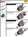
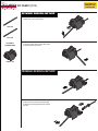
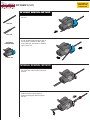
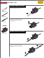
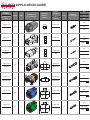
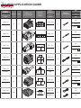
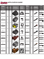
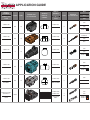
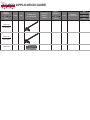
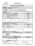
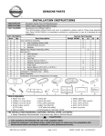
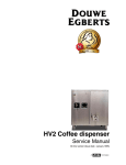
1
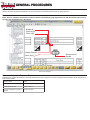
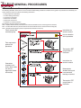
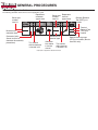
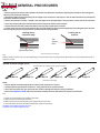
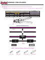
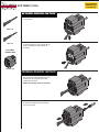
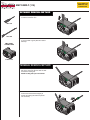
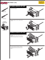
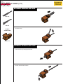
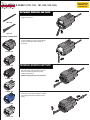
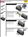
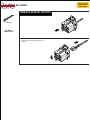
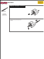
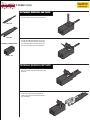
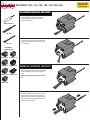
TABLE OF CONTENTS
GENERAL PROCEDURES.................... 2
HK FAMILY (169)................................. 23
Precautions ...................................... 2
Procedures........................................ 2
HS FAMILY (107, 109, 110, 111, 112,
125, 165, 188)....................................... 24
Connector Inspection: Repair vs.
Replace.............................................. 2
L FAMILY.............................................. 25
MF FAMILY........................................... 26
How to Use Connector Disassembly
Procedures........................................ 3
MM FAMILY.......................................... 27
How to Use Application Guide........ 4
NS FAMILY (114, 132, 133, 134, 135,
158)...................................................... 28
Retainer/Terminal Removal Tools... 5
P FAMILY (164).................................... 29
Spread Terminal Gauges (STG)....... 6
RH FAMILY (101, 116, 150, 162, 176,
185, 186)............................................... 30
Automatic Wire Stripper................... 7
Flameless Heat Gun, Refill
Cartridge, and Solder Sleeve
Connectors........................................ 7
Aluminum Wiring.............................. 8
Harness Repair Kit Suggestion
Form.................................................. 9
RK FAMILY (104, 120, 121, 146).......... 31
RK FAMILY (151, 152, 161, 175).......... 32
RS FAMILY (106, 108, 113, 117, 119,
148, 149, 153, 166, 170, 171, 189)........ 33
SEA FAMILY (140, 141)....................... 34
A FAMILY (144, 145, 155, 156, 159)..... 10
TH FAMILY (127, 128, 130, 131, 154,
157)...................................................... 35
AFZ FAMILY (160)................................ 11
TH FAMILY (126, 129).......................... 36
AMP FAMILY (115)............................... 12
TK FAMILY (136, 137, 138, 178, 179,
180)...................................................... 37
AMP FAMILY (123)............................... 13
BD FAMILY (139)................................. 14
BS FAMILY (103, 105, 147).................. 15
BS FAMILY (173).................................. 16
U FAMILY (124).................................... 38
WBS FAMILY (142, 143)....................... 39
WF FAMILY (174)................................. 40
C FAMILY (177).................................... 17
WHX FAMILY (172).............................. 41
ECM FAMILY (AMP)............................. 19
WP8 FAMILY (163)............................... 44
ECM FAMILY (Molex)........................... 20
X FAMILY (187).................................... 45
ECM FAMILY (Yazaki).......................... 21
YV FAMILY........................................... 46
FC FAMILY (118).................................. 22
APPLICATION GUIDE......................... 47
E FAMILY (102, 122 , 181, 182, 183, 184). WP FAMILY (167)................................. 42
18
WP FAMILY (168)................................. 43
567938 REV D
GENERAL PROCEDURES
Precautions
Observe the safety precautions described in the service manual for the electrical systems that are being repaired.
Procedures
NOTE: The wire crimped in the terminals included in this kit is the maximum gauge approved for use with the terminal. This wire may
be larger than the existing wire in the vehicle.
Number of
Terminals (2)
Family (HS)
Gender (Female)
Service Manual
Symbol
Color (Gray)
PDF Format CONSULT
Connector Inspection: Repair vs. Replace
To determine if terminal replacement or connector replacement is best, inspect the connector as listed below. Individual terminal replacement is
better when possible.
Inspection Result
Repair
No damage to connector housing
Replace terminal
Terminal failed STG test
Replace terminal
Connector is damaged, crushed, or
distorted
Replace connector
GENERAL PROCEDURES
How to Use Connector Disassembly Procedures
The following illustration shows how to use the connector disassembly procedures contained in this guide. The procedures are divided by connector family and each one contains the following information:
• Tool(s) required for procedure
• Terminal locking tab location
• Connectors in the family
• Removal of the retainer
• Removal of the terminal
• Animation of removal procedure
The following acronyms appear in this guide:
RRT – Retainer Removal Tool (retainer/terminal removal tool blade used for removing terminal retainer)
TRT – Terminal Removal Tool (retainer/terminal removal tool blade used to release terminal locking tab)
STG – Spread Terminal Gauge (used to inspect female terminals for loose fit)
Family name of the
connector group
Instructions for
retainer removal
Link to animation
of this procedure
Tools required to
perform this
procedure
Text explains RRT
usage shown in
illustration
Instructions for
terminal removal
Connectors
included in this
family (these views
are links to
Application Guide
information)
Note explains
whether locking tab
is on connector
housing or terminal
Text explains TRT
usage shown in
illustration
Description of Connector Disassembly Procedure Information
GENERAL PROCEDURES
How to Use Application Guide
The following illustration shows how to use the application guide.
Bosch part
number
from kit
Bosch part Represents
terminal
number
appearance
from kit
Represents
connector
appearance
Bosch
NUMBER
CONNECTOR
FAMILY TRAY
TYPE
CONNECTOR
ILLUSTRATION
SERVICE
MANUAL
SYMBOL
J-48817-101
Manufacturer
connector type
Connector family
(these are links to
connector disassembly
procedures)
Bosch
NUMBER
TERMINAL
TYPE
RRT
TERMINAL
TRAY ILLUSTRATION
1
5
1 2 3 4 5 6
RH06FB
RHFM YZK-N
Manufacturer
terminal type
Tray number
where connector
is located in kit
Connector
face shown
in service
manual
TRT
STG
01A
J-48817-201
RH
Tray number
where terminal
is located in kit
Description of Application Guide Information
Retainer Removal
Tool (RRT) part
number
10A
J-48817-5
Terminal
Removal Tool
(TRT) part
number
Spread terminal gauge
(STG) part number (female
terminals only)
GENERAL PROCEDURES
Retainer/Terminal Removal Tools
01A
09A
03A
16A
02A
12A
13A
07A
13A
10A
08A
01
11A
10A
06A
01
06A
05A
04A
J-48817-1 Retainer/Terminal Removal Tool
Blade number
01A
02A
03A
04A
05A
06A*
07A
08A
09A
10A*
11A
12A
13A*
16A
01*
Application
Universal
M-HS
RT-RS
Screwdriver
TH-HS
ABS-M
A-HS
P-HS
NS-HS
RH-HS
TK-HS
FG-HS
ABS-SM
Molex
Separators
* The tool contains two of these.
J-47003-11 Retainer Removal Tool
GENERAL PROCEDURES
NOTE:
• Performing terminal removal and installation should be easy. Read each step before beginning the procedure. Not reading each
step may lower technician efficiency.
• Determine whether the terminal locking tab is integral to the connector or the terminal - this will affect the direction of the motion
required to release the terminal.
• Perform tool selection carefully – though a tool may appear to be the right shape, it may not be the correct tool for the connector.
• Use of two blades (with spacer between them) will be required to release some terminals.
• Unless otherwise directed, position the blade so the long side is against the connector.
• In some cases, the wire must be pushed into the connector slightly to relieve pressure applied to the locking tab by the terminal.
Not relieving this pressure may prevent the terminal from becoming unlocked.
Locking tab on
connector body
Locking tab on
terminal
Tool
Contact
Point
Tool Contact Point
Tool contact point on locking tab
Use
Retainer/terminal removal tool use varies depending on which connector type is being serviced. Read all of the notes provided above prior to
beginning a repair.
Spread Terminal Gauges (STG)
Terminal passes test if spread terminal gauge compresses.
J-48817-2
J-48817-3
J-48817-4
J-48817-5
J-48817-6
Spread Terminal Gauges
NOTE:
• Use the Spread Terminal Gauge (STG) to inspect female terminals for loose fit.
• Visually inspecting terminals is insufficient – using the STG test is the best method.
• Use of the wrong STG may give inaccurate test results or damage the terminal, causing problems.
• Refer to the Application Guide within this document to determine which STG should be used for each terminal.
Use
1.Select the correct STG for the terminal to be tested.
2.Align the tip of the STG with the terminal.
3.While moving the connector slightly, gently apply pressure to the STG.
4.If the STG enters the terminal without compressing, replace the terminal.
Animation of terminal that passes STG test
Animation of terminal that fails STG test
J-48817-7
GENERAL PROCEDURES
Automatic Wire Stripper
WARNING:
• Always wear approved eye protection
• NOT insulated. Plastic-dipped or slip-on plastic handles are NOT intended for protection against electrical shock.
• Never use on or near live electrical circuits.
J-35615 (11062 or 11063)
Automatic Wire Stripper
J-47003-10 (11075, use with 11062) or
J-47003-12 (11074, use with 11063) Die
Use
The following procedure describes how to use the automatic wire stripper to remove insulation from 8-22 or 16-26 AWG wire without nicking or
fraying.
1.Choose and install the correct stripper die for the wire gauge you are reparing.
2.Adjust the wire stop to the desired stripping length. The recommended length for J-47003 Solder Sleeves is approximately 10mm (0.4 inch).
3.With the open side of the jaws toward you (wire stop to the right), place the wire in the appropriate size stripping hole with the end touching
the wire stop. Refer to the blade for AWG and mm size markings.
4.Squeeze the handles together to strip the wire. Release pressure from the handles and remove the wire.
Flameless Heat Gun, Refill Cartridge, and Solder Sleeve Connectors
J-46538
CF-30C
J-47003-2,3,4,5
J-46538 Flameless Heat Gun, CF-30C Refill Cartridge, and J-47003 Solder Sleeve Connectors
Use
Refer to NTB03-078 for proper usage of Essential Tool J-46538 Flameless Heat Gun and Essential Tool J-47003 Solder Sleeve Connectors.
Refill cartridges part number CF-30C are available at http://www.solderit.com/shop/item.aspx?itemid=101. Using generic refill cartridges is not
recommended, as they do not fit or function as intended. Soldering will take longer and the tool may have ignition problems. Only use refill cartridges from Solder-It.
GENERAL PROCEDURES
Aluminum Wiring
! CAUTION: Crimp Repair Only! Do not use solder. Use J-48817-8 crimping tool only
CAUTION: Aluminum is susceptible to cross contamination. Do not use the crimping pliers on copper components.
Copper vs Aluminum Wire Reference Chart
Size mm2
Copper Wire
Outer Diameter STD mm
Aluminum Shrink Tube
Splice
Size mm2
Aluminum Wire
Outer Diameter STD mm
0.5
0.85
1.25
1.6
1.8
2.1
J-48817-801 J-48817-803
J-48817-801 J-48817-803
J-48817-801 J-48817-803
0.75
1.25
1.5
1.4
1.8
1.85
2
2.6
J-48817-802 J-48817-804
2.5
2.8
J-48817-8
Crimping Plier Usage
Crimping Pliers For Aluminum Wire Repair
Only
Tool Gap Use: 1.5
Tool Gap Use: 1.5
Tool Gap Use: 1.5
Tool Gap Use: 2.0
2.0
1.5
Joints for Aluminum wire
Aluminum Wire
Copper Wire
Aluminum Splice
Heat Shrink
J-48817 Aluminum Splices (Aluminum Use Only)
J-48817-801
J-48817-802
J-48817-803
J-48817-804
GENERAL PROCEDURES
Harness Repair Kit Suggestion Form
• Use the Tools and Equipment Suggestion Form to make suggestions about how to improve the content of this kit.
• Replacement parts for this kit are available through Tech-Mate. To place an order, please call 1-800-662-2001 or visit www.nissantechmate.
com.
• Many of the connectors required for Nissan and Infiniti vehicle repairs are in this kit. Additional parts may be available even though they are
not included in this kit.
CLICK HERE TO
ANIMATE THIS
PROCEDURE
A FAMILY (144, 145, 155, 156, 159)
RETAINER REMOVAL METHOD
1. Place the RRT (01A) in the small hole
between the retainer and the connector
with the long side toward the retainer.
RRT 01A
TRT 09A
A FAMILY
CONNECTORS
2. Use the RRT as a lever to gently lift the
end of the retainer out of the connector.
Pull the retainer outward until it stops and
fold it away from the wires.
J-48817-144
TERMINAL REMOVAL METHOD
J-48817-145
1. Insert the TRT (09A) into the slot on the
side of the connector. Be sure that the TRT
contacts the locking tab.
NOTE: Locking tab is part of connector.
J-48817-155
2. Move the TRT downward slightly to
release the locking tab and then pull the
wire out slowly.
2
J-48817-156
1
J-48817-159
CLICK HERE TO
ANIMATE THIS
PROCEDURE
AFZ FAMILY (160)
RETAINER REMOVAL METHOD
1. Place the RRT (11A) at the bottom edge
of the retainer.
RRT 11A
TRT 11A
2. Use the RRT as a lever to gently lift the
retainer. Remove the retainer from the
connector.
AFZ FAMILY
CONNECTORS
J-48817-160
TERMINAL REMOVAL METHOD
1. Insert the TRT (11A) straight into the
slot on the face of the connector near the
terminal with the long side of the TRT
touching the terminal.
NOTE: Locking tab is part of connector.
2. Release the locking tab and then pull
the wire out slowly.
2
1
CLICK HERE TO
ANIMATE THIS
PROCEDURE
AMP FAMILY (115)
RETAINER REMOVAL METHOD
1. Slide the RRT (07A) between the retainer and the connector face.
RRT 07A
TRT 09A
AMP FAMILY
CONNECTORS
2. Use the RRT to gently slide the retainer
sideways.
J-48817-115
TERMINAL REMOVAL METHOD
1. Insert the TRT (09A) into the slot on the
side of the connector. Be sure that the TRT
contacts the locking tab.
NOTE: Locking tab is part of terminal.
2. Move the TRT downward slightly to
release the locking tab and then pull the
wire out slowly.
1
2
CLICK HERE TO
ANIMATE THIS
PROCEDURE
AMP FAMILY (123)
RETAINER REMOVAL METHOD
1. Slide the RRT (11A) into the hole above
the left terminal.
RRT 11A
TRT 11A
AMP FAMILY
CONNECTORS
2. Use the RRT as a lever to gently lift the
retainer until it releases from the connector.
J-48817-123
TERMINAL REMOVAL METHOD
1. Insert the TRT (11A) into the slot in the
retainer. Be sure that the TRT contacts the
locking tab.
NOTE: Locking tab is part of terminal.
2. Move the TRT downward slightly to
release the locking tab and then pull the
wire out slowly.
1
2
CLICK HERE TO
ANIMATE THIS
PROCEDURE
BD FAMILY (139)
RETAINER REMOVAL METHOD
1. Place the RRT (01A) in the slot near the
center of the retainer.
RRT 01A
TRT 11A
2. Use the RRT as a lever to gently lift the
retainer.
BD FAMILY
CONNECTORS
J-48817-139
TERMINAL REMOVAL METHOD
1. Insert the TRT (11A) straight into the
slot on the face of the connector near the
terminal.
NOTE: Locking tab is part of connector.
2. Press the TRT into the slot to release
the locking tab and then pull the wire out
slowly.
2
1
CLICK HERE TO
ANIMATE THIS
PROCEDURE
BS FAMILY (103, 105, 147)
RETAINER REMOVAL METHOD
RRT 01A
1. Connector 103 (shown): Place the RRT
(01A) under the retainer.
Connector 105: Place the RRT (01A)
under the locking tab on one side of the
connector.
TRT 06A
BS FAMILY
CONNECTORS
2. Connector 103 (shown): Use the RRT
as a lever to gently lift the retainer. Fold the
retainer away from the wires.
Connector 105: Use the RRT as a lever to
gently lift the retainer locking tab. Repeat
the process on the other side of the connector. Remove the retainer.
J-48817-103
TERMINAL REMOVAL METHOD
1. Insert the two TRTs (06A) straight into
the slots on the face of the connector
above and below the terminal. Be sure that
the two TRTs contact the locking tabs.
J-48817-105
NOTE: Locking tabs are part of terminal.
J-48817-147
2. Press the two TRTs into the slots to
release the locking tabs and then pull the
wire out slowly.
2
1
BS FAMILY (173)
RETAINER REMOVAL METHOD
1. Place the RRT (04A) under the edge of
the retainer.
RRT 04A
TRT 12A
2. Use the RRT as a lever to gently lift the
retainer. Do not remove the retainer from
the connector.
BS FAMILY
CONNECTORS
J-48817-173
TERMINAL REMOVAL METHOD
1. Insert the TRT (12A) straight into the
slots on the face of the connector on both
sides of the terminal.
NOTE: Locking tabs are part of terminal.
2. Press the TRT into the slots to release
the locking tabs and then pull the wire out
slowly.
CLICK HERE TO
ANIMATE THIS
PROCEDURE
CLICK HERE TO
ANIMATE THIS
PROCEDURE
C FAMILY (177)
RETAINER REMOVAL METHOD
1. Insert RRT (01A) in the latch as shown.
RRT 01A
TRT 11A
C FAMILY
CONNECTORS
2. Pull the tool up.
J-48817-177
TERMINAL REMOVAL METHOD
1. Insert TRT (11A) as shown, the connector lock will move up releasing the terminal.
2. Pull on the terminal to remove.
2
1
CLICK HERE TO
ANIMATE THIS
PROCEDURE
E FAMILY (102, 122 , 181, 182, 183, 184)
RETAINER REMOVAL METHOD
1. Place the RRT (04A) in the slot at the
edge of the retainer.
RRT 04A
TRT 11A
E FAMILY CONNECTORS
2. Use the RRT as a lever to gently lift the
retainer. Remove the retainer from the
connector.
J-48817-102
J-48817-122
TERMINAL REMOVAL METHOD
1. Insert the TRT (11A) straight into the
slot on the face of the connector near the
terminal with the long side of the TRT
touching the terminal.
NOTE: Locking tab is part of connector.
J-48817-181
J-48817-182
2. Move the TRT upward slightly to release
the locking tab and then pull the wire out
slowly.
2
J-48817-183
1
J-48817-184
CLICK HERE TO
ANIMATE THIS
PROCEDURE
ECM FAMILY (AMP)
RETAINER REMOVAL METHOD
1. Release the cover by pressing the locks.
RRT 01A
Rear View
TRT 13A
TRT 06A
ECM FAMILY
CONNECTORS
2. Use the RRT (01A) as a lever to gently
release the top of the yellow retainer. Repeat operation on the opposite side of the
retainer. Do not remove the retainer from
the connector.
On the opposite side of the connector,
place the RRT (01A) in between the connector and yellow retainer Use the RRT
as a lever to gently release the retainer.
Remove the retainer from the connector.
TERMINAL REMOVAL METHOD
2
1. For smaller terminals, position the TRT
(13A) into the lock cavity. Move the TRT
downward slightly to release the locking
tab. Pull the wire back to remove the terminal while the TRT is inserted.
NOTE: Locking tab is part of connector.
1
2. For the larger terminals, insert the two
TRTs (06A) straight into the slots on the
face of the connector above and below
the terminal. Be sure that the two TRTs
contact the locking tabs.
2
NOTE: Locking tab is part of terminal.
1
CLICK HERE TO
ANIMATE THIS
PROCEDURE
ECM FAMILY (Molex)
RETAINER REMOVAL METHOD
1. Cut and remove the tie strap from rear
of connector. Unlock both side locks using
RRT (01A). While releasing the locks push
and remove the cover.
2
1
RRT 01A
Rear View
TRT 07A
ECM FAMILY
CONNECTORS
2. Release secondary retainer using RRT
(01A).
3. Pull the retainer up to the position
shown.
TERMINAL REMOVAL METHOD
1. Position the TRT (07A) in the lock cavity.
Insert the TRT to release the lock terminal.
Pull the wire back to remove the terminal
while the TRT is inserted.
2
NOTE: Do not lift the pick tool to avoid
lock damage.
NOTE: Locking tab is part of terminal.
1
CLICK HERE TO
ANIMATE THIS
PROCEDURE
ECM FAMILY (Yazaki)
RETAINER REMOVAL METHOD
1. Cut and remove the tie strap from rear
of connector. Unlock each side of the rear
cover using RRT (01A). Apply pressure
while releasing the locks push and remove
the cover.
2
1
RRT 01A
Rear View
TRT 07A
ECM FAMILY
CONNECTORS
2. To release secondary retainer, lift the
lower lock while pinching the secondary
retainer to release.
2
1
2
3. Pull retainer out firmly.
TERMINAL REMOVAL METHOD
1. Insert the TRT (07A) 1mm between
terminal and lock . Pull the wire back to
remove the terminal.
2
NOTE: Do not lift the pick tool to avoid
lock damage.
NOTE: Locking tab is part of connector.
After repair, align secondary retainer
according to terminal sizes, press lock on
both sides and push in firmly until reaching
bottom of connector and release.
1
FC FAMILY (118)
RETAINER REMOVAL METHOD
1. Place the RRT (04A) under the edge of
the retainer.
RRT 04A
TRT 12A
FC FAMILY
CONNECTORS
2. Use the RRT as a lever to gently lift the
retainer. Do not remove the retainer from
the connector.
J-48817-118
TERMINAL REMOVAL METHOD
1. Insert the TRT (12A) straight into the
slots on the face of the connector on both
sides of the terminal.
NOTE: Locking tabs are part of terminal.
2. Press the TRT into the slots to release
the locking tabs and then pull the wire out
slowly.
CLICK HERE TO
ANIMATE THIS
PROCEDURE
CLICK HERE TO
ANIMATE THIS
PROCEDURE
HK FAMILY (169)
RETAINER REMOVAL METHOD
1. Insert RRT (01A) as shown.
RRT 01A
TRT 01A
HK FAMILY
CONNECTORS
2. Pull out the yellow center retainer.
2
1
J-48817-169
TERMINAL REMOVAL METHOD
1. Insert TRT (01A) as shown.
2. Push to release the cavity lock and pull
the terminal out.
2
1
HS FAMILY (107, 109, 110, 111, 112, 125, 165, 188)
RETAINER REMOVAL METHOD
1. All except connector 165: Place the RRT
(02A) in the small hole in the retainer.
Connector 165: Place RRT (04A) in the
retainer slot.
TRT 01A
RRT 02A
RRT 04A
2. Use the RRT as a lever to gently lift the
retainer. Remove the retainer from connectors 110 and 125 only.
TRT 07A
HS FAMILY
CONNECTORS
J-48817-107
J-48817-110
J-48817-109
J-48817-111
TERMINAL REMOVAL METHOD
1. All except connector 165: Insert the TRT
(01A) straight into the slot on the face of
the connector near the terminal with the
long side of the TRT touching the terminal.
Connector 165: Insert TRT (07A) straight
into the slot on the face of the connector
near the terminal.
NOTE: Locking tab is part of connector.
J-48817-112
J-48817-165
J-48817-125
J-48817-188
2. Move the TRT slightly (upward for
connectors 109, 110 and 125; downward
for connectors 107, 111, 112 and 165) to
release the locking tab and then pull the
wire out slowly.
CLICK HERE TO
ANIMATE THIS
PROCEDURE
CLICK HERE TO
ANIMATE THIS
PROCEDURE
L FAMILY
RETAINER REMOVAL METHOD
1. Insert RRT (04A) as shown.
RRT 04A
TRT 04A
L FAMILY CONNECTORS
2. Pull the retainer up.
TERMINAL REMOVAL METHOD
1. Insert TRT (04A) in the front of the connector as shown.
2. Open the cavity lock and pullout the
terminal.
2
1
CLICK HERE TO
ANIMATE THIS
PROCEDURE
MF FAMILY
TERMINAL REMOVAL METHOD
1. Insert TRT (02A) as shown.
TRT 02A
MF FAMILY
CONNECTORS
2. Open the cavity lock and pullout the
terminal.
2
1
CLICK HERE TO
ANIMATE THIS
PROCEDURE
MM FAMILY
TERMINAL REMOVAL METHOD
1. Insert TRT (01A) as shown.
TRT 01A
MM FAMILY
CONNECTORS
2. Open the cavity lock and pullout the
terminal.
2
1
CLICK HERE TO
ANIMATE THIS
PROCEDURE
NS FAMILY (114, 132, 133, 134, 135, 158)
RETAINER REMOVAL METHOD
1. All except connectors 114 and 135:
Place the RRT (09A) in the small hole
behind the retainer.
Connectors 114, 135: Place the RRT (09A)
in the slot on the side of the connector.
RRT 09A
TRT 09A
NS FAMILY
CONNECTORS
2. Press the RRT gently until the retainer
releases from the connector. Do not remove the retainer from the connector.
J-48817-114
TERMINAL REMOVAL METHOD
J-488817-132
1. Insert the TRT (09A) as shown. Ensure
that the TRT contacts the locking tab.
NOTE: Locking tab is part of connector.
J-488817-133
J-488817-134
J-488817-135
J-48817-158
2. Move the tool downward slightly to
release the locking tab and then pull the
wire out slowly.
2
1
P FAMILY (164)
RETAINER REMOVAL METHOD
1. Place the RRT (04A) into the connector
lock area and insert it into the retainer slot.
RRT 01A
TRT 08A
P FAMILY CONNECTORS
2. Push the RRT towards the rear of the
connector to release the lock. The retainer is unlocked when it moves out. Do not
remove the retainer from the connector.
J-48817-164
TERMINAL REMOVAL METHOD
1. Insert the TRT (04A) straight into the
slot on the face of the connector above the
terminal.
2. Move the TRT downward slightly to
release the locking tab and then pull the
wire out slowly.
CLICK HERE TO
ANIMATE THIS
PROCEDURE
CLICK HERE TO
ANIMATE THIS
PROCEDURE
RH FAMILY (101, 116, 150, 162, 176, 185, 186)
RETAINER REMOVAL METHOD
1. All except connector 186: Place the RRT
(01A) against the side of the retainer.
Connector 186: Using RRT J-47003-11,
remove the retainer.
RRT J-47003-11
RRT 01A
TRT 10A
2. Use the RRT as a lever to gently lift the
retainer. Do not remove the retainer from
the connector.
RH FAMILY
CONNECTORS
J-48817-101 J-48817-176
J-48817-116 J-48817-185
J-48817-150 J-48817-186
TERMINAL REMOVAL METHOD
1. Position the two TRTs (10A) long side
down and align with the slots on both sides
of the terminal opening in the connector
face.
NOTE: Locking tabs are part of connector.
J-48817-162
2. Slide the TRTs into the slots in the connector and be sure that they contact the
locking tabs. Press the two TRTs into the
slots to release the locking tabs and then
pull the wire out slowly.
2
1
RK FAMILY (104, 120, 121, 146)
CLICK HERE TO
ANIMATE THIS
PROCEDURE
RETAINER REMOVAL METHOD
1. Place the RRT (01A) in the slot between
the retainer and the connector.
RRT 01A
TRT 11A
RK FAMILY
CONNECTORS
2. Use the RRT as a lever to gently lift the
retainer. Remove the retainer from the
connector.
J-48817-104
TERMINAL REMOVAL METHOD
J-48817-120
1. Insert the TRT (01A for 104 and 121,
11A for 120) directly above the terminal
with the long side of the TRT touching the
terminal.
NOTE: Locking tab is part of connector.
J-48817-121
2. Move the TRT downward slightly to
release the locking tab and then pull the
wire out slowly.
J-48817-146
2
CLICK HERE TO
ANIMATE THIS
PROCEDURE
RK FAMILY (151, 152, 161, 175)
RETAINER REMOVAL METHOD
1. Insert (RRT J-47003-11) into the retainer middle cavity.
RRT J-47003-11
TRT 11A
RK FAMILY
CONNECTORS
2. Pull the RRT outward to remove the
retainer.
J-48817-151
TERMINAL REMOVAL METHOD
J-48817-152
1. Insert the TRT (11A) into slot just above
terminal.
J-48817-161
2. Move the TRT downward to release the
lock and then pull the wire out slowly.
2
J-48817-175
RS FAMILY (106, 108, 113, 117, 119, 148, 149, 153, 166,
170, 171, 189)
CLICK HERE TO
ANIMATE THIS
PROCEDURE
RETAINER REMOVAL METHOD
RRT 03A
1. All except connector 106: Place the RRT
(03A) in the slot between the retainer and
the connector with the barb toward the
retainer. When fully inserted, the barb will
engage a hole in the retainer.
Connector 106: Place the RRT (03A) in the
slot on the side of the retainer.
RRT 02A
TRT 11A
RS FAMILY
CONNECTORS
J-48817-106
J-48817-108
J-48817-113
J-48817-117
J-48817-119
J-48817-148
J-48817-149
J-48817-153
J-48817-166
J-48817-170
J-48817-171
J-48817-189
2. All except connector 106: Pull the RRT
straight away from the connector. Remove
the retainer from the connector.
Connector 106: Use the RRT as a lever to
gently lift the retainer. Remove the retainer
from the connector.
TERMINAL REMOVAL METHOD
1. Connectors 106, 113, 117, 119: Insert
the TRT (11A) straight into the connector
along the visible side of the terminal with
the long side of the TRT touching the
terminal.
NOTE: Locking tab is part of connector.
2. Press the TRT into the slot to release
the locking tab and then pull the wire out
slowly.
2
1
CLICK HERE TO
ANIMATE THIS
PROCEDURE
SEA FAMILY (140, 141)
RETAINER REMOVAL METHOD
1. Place the RRT (01A) in the slot next to
the terminal cavities on the wire side of
the connector. Slide the RRT along the
inboard surface of the slot until it contacts
the locking tab of the retainer.
RRT 01A
TRT 11A
SEA FAMILY
CONNECTORS
2. Use the RRT as a lever to gently lift the
retainer locking tab. Repeat the process on
the other end of the connector and remove
the retainer from the terminal side of the
connector.
J-48817-140
TERMINAL REMOVAL METHOD
1. Place the TRT (11A) against the visible
side of the terminal with the long side of
the TRT touching the terminal.
NOTE: Locking tab is part of connector.
J-48817-141
2. Press the TRT against the locking tab to
release it and then pull the wire out slowly.
2
1
CLICK HERE TO
ANIMATE THIS
PROCEDURE
TH FAMILY (127, 128, 130, 131, 154, 157)
RETAINER REMOVAL METHOD
RRT 07A
TRT 07A
TH FAMILY
CONNECTORS
J-48817-127
1. Place the RRT (07A) between the connector and the rear edge of the retainer.
Use the RRT as a lever to gently lift the
rear edge of the retainer.
CAUTION: Terminals are NOT interchangeable between old and new style TH
connectors. The old style connector
face has one large hole and the new
style has many small holes. The terminal repair kit contains only the new
style connectors and terminals. If an
old style connector or terminal requires
service, the connector and terminals
must be replaced with the new style.
2. Slide the retainer toward the wire side of
the connector. Do not remove the retainer
from the connector.
J-48817-128
TERMINAL REMOVAL METHOD
1. Insert the TRT (07A) straight into the
hole on the face of the connector near
the terminal with the long side of the TRT
toward the terminal.
J-48817-130
Note: Locking tab is part of connector.
J-48817-131
2. Press the TRT into the hole to release
the locking tab and then pull the wire out
slowly.
2
J-48817-154
1
J-48817-157
CLICK HERE TO
ANIMATE THIS
PROCEDURE
TH FAMILY (126, 129)
RETAINER REMOVAL METHOD
1. Place the RRT (07A) under the edge of
the retainer.
RRT 07A
TRT 07A
TH FAMILY
CONNECTORS
CAUTION: Terminals are NOT interchangeable between old and new style TH
connectors. The old style connector
face has one large hole and the new
style has many small holes. The terminal repair kit contains only the new
style connectors and terminals. If an
old style connector or terminal requires
service, the connector and terminals
must be replaced with the new style.
2
1
2. Use the RRT as a lever to gently unlock
the edge of the retainer from the connector. Repeat the process to completely
release the retainer.
J-48817-126
TERMINAL REMOVAL METHOD
J-48817-129
1. Insert the TRT (07A) straight into the
hole on the face of the connector near
the terminal with the long side of the TRT
toward the terminal.
NOTE: Locking tab is part of connector.
2. Press the TRT into the hole to release
the locking tab and then pull the wire out
slowly.
2
1
CLICK HERE TO
ANIMATE THIS
PROCEDURE
TK FAMILY (136, 137, 138, 178, 179, 180)
RETAINER REMOVAL METHOD
1
1. Place the RRT (01A) between the connector and the rear edge of the retainer.
Use the RRT as a lever to gently lift the
rear edge of the retainer.
2
RRT 01A
TRT 11A
TK FAMILY
CONNECTORS
2. Slide the retainer toward the wire side of
the connector. Do not remove the retainer
from the connector.
J-48817-136
J-48817-137
TERMINAL REMOVAL METHOD
1. Insert the TRT (11A) straight into the
hole on the face of the connector near
the terminal with the long side of the TRT
toward the terminal. Be sure that the TRT
contacts the locking tab.
NOTE: Locking tab is part of connector.
J-48817-138
J-48817-178
2. Press the TRT into the slot to release
the locking tab and then pull the wire out
slowly.
2
J-48817-179
1
J-48817-180
CLICK HERE TO
ANIMATE THIS
PROCEDURE
U FAMILY (124)
RETAINER REMOVAL METHOD
1. Place the RRT (04A) on the retainer
locking tab on the wire side of the connector.
RRT 04A
TRT 01A
U FAMILY
CONNECTORS
2. Use the RRT to gently depress the locking tab far enough to remove it from the
slot in the connector. Repeat the process
on the other locking tab and remove the
retainer.
J-48817-124
TERMINAL REMOVAL METHOD
1. Insert the TRT (01A) into the slot above
the terminal with the long side of the TRT
touching the terminal. Be sure that the
TRT contacts the locking tab.
NOTE: Locking tab is part of connector.
2. Move the TRT downward slightly to
release the locking tab and then pull the
wire out slowly.
2
1
CLICK HERE TO
ANIMATE THIS
PROCEDURE
WBS FAMILY (142, 143)
TERMINAL REMOVAL METHOD
1. Insert the TRT (06A) straight into face
of the connector on the outboard side of
the terminal with the long side of the TRT
toward the terminal.
TRT 06A
NOTE: WBS connectors are not equipped with retainers.
NOTE: Locking tab is part of terminal.
WBS FAMILY
CONNECTORS
2. Press the TRT into the connector to
release the locking tab and then pull the
wire out slowly.
2
J-48817-142
1
J-48817-143
WF FAMILY (174)
RETAINER REMOVAL METHOD
1. Using the RRT (04A) pry up on the secondary lock (cover) and remove.
RRT 04A
TRT 04A
WF FAMILY
CONNECTORS
2. Using the RRT (04A) release both sides
of the back lock and remove.
J-48817-174
TERMINAL REMOVAL METHOD
1. Insert the TRT (04A).
2. Move the TRT (04A) downward slightly
to release the locking tab and then pull the
wire out.
CLICK HERE TO
ANIMATE THIS
PROCEDURE
WHX FAMILY (172)
RETAINER REMOVAL METHOD
1. Place the RRT (11A) into the retainer
slot.
RRT 11A
TRT 11A
WHX FAMILY
CONNECTORS
2. Using the RRT (11A) pry the lock up
and remove.
J-48817-172
TERMINAL REMOVAL METHOD
1. Insert the TRT (11A) into the slot on the
face of the connector below the terminal.
2. Push TRT (11A) down to release the
terminal and then pull out the wire.
CLICK HERE TO
ANIMATE THIS
PROCEDURE
WP FAMILY (167)
RETAINER REMOVAL METHOD
1. Place the RRT (04A) into the connector
lock area.
RRT 04A
TRT 13A
WP FAMILY
CONNECTORS
2. Push the RRT (04A) towards the rear of
the connector to release the lock, repeat
for the other side. The retainer is unlocked
when it moves out.
J-48817-167
TERMINAL REMOVAL METHOD
1. Insert the TRT (13A) straight into the
slot on the face of the connector above the
terminal.
2. Move the TRT (13A) up slightly to
release the locking tab and then pull the
wire out.
CLICK HERE TO
ANIMATE THIS
PROCEDURE
WP FAMILY (168)
RETAINER REMOVAL METHOD
1. Place the RRT (J-47003-11) into the
retainer slot and pull the retainer out.
RRT J-47003-11
RRT 04A
2. Place the RRT (04A) towards the rear of
the connector to release the lock, repeat
for the other side.
TRT 01A
WP FAMILY
CONNECTORS
TERMINAL REMOVAL METHOD
J-48817-168
1. Insert the TRT (01A).
2. Move the TRT (01A) downward slightly
to release the locking tab and then pull the
wire out.
CLICK HERE TO
ANIMATE THIS
PROCEDURE
CLICK HERE TO
ANIMATE THIS
PROCEDURE
WP8 FAMILY (163)
RETAINER REMOVAL METHOD
1. Place the RRT (04A) into the connector
lock area and insert it into the retainer slot.
RRT 04A
TRT 04A
WP8 FAMILY
CONNECTORS
2. Push the RRT towards the rear of the
connector to release the lock. The retainer is unlocked when it moves out. Do not
remove the retainer from the connector.
J-48817-163
TERMINAL REMOVAL METHOD
1. Insert the TRT (04A) straight into the
slot on the face of the connector above the
terminal.
2. Move the TRT downward slightly to
release the locking tab and then pull the
wire out slowly.
2
1
CLICK HERE TO
ANIMATE THIS
PROCEDURE
X FAMILY (187)
RETAINER REMOVAL METHOD
1. Insert RRT (01A) into both sides as
shown.
RRT 01A
TRT 01A
X FAMILY CONNECTORS
2. Pull up and release lock.
J-48817-187
TERMINAL REMOVAL METHOD
1. Insert TRT (01A) in the front of the connector as shown.
2. Open the cavity lock and pullout the
terminal.
2
1
CLICK HERE TO
ANIMATE THIS
PROCEDURE
YV FAMILY
RETAINER REMOVAL METHOD
1. Insert RRT (01A) as shown.
RRT 01A
TRT 13A
YV FAMILY
CONNECTORS
2. Pull up retainer.
TERMINAL REMOVAL METHOD
1. Insert TRT (13A) in the front of the connector as shown.
2. Open the cavity lock and pullout the
terminal.
2
1
APPLICATION GUIDE
BOSCH
NUMBER
CONNECTOR
TYPE
FAMILY
TRAY
CONNECTOR
ILLUSTRATION
SERVICE
MANUAL
SYMBOL
BOSCH
NUMBER
RRT
TRAY
TERMINAL
TYPE
TERMINAL
ILLUSTRATION
TRT
STG
01A
J-48817-101
J-48817-201
RH
1
RH06FB
1 2 3 4 5 6
5
10A
RHFM YZK-N
J-48817-5
04A
J-48817-102
J-48817-202
E
1
E03FGY-RS
5
1
2
3
11A
RSF-M-SWSN
J-48817-3
01A
J-48817-103
J-48817-203
BS
1
1
BS02FB
5
2
06A
185026-1
J-48817-3
01A
J-48817-104
J-48817-204
RK
1
RK03FB
01A or 11A
1
2
3
RKF-M SN
J-48817-5
04A or 01A
J-48817-105
BS
1
106265
1
2
3
J-48817-205
4
5
6
964286-1AU
5
06A
J-48817-3
04A or 03A
J-48817-106
RS
1
1
2
RS04FG-GY
J-48817-206
11A
RSF-S-SWSN
3
J-48817-3
4
02A
J-48817-107
J-48817-207
HS
HS02FGY
1
1
2
01A
WTS090F-M
J-48817-3
APPLICATION GUIDE
BOSCH
NUMBER
CONNECTOR
TYPE
FAMILY
TRAY
BOSCH
NUMBER
SERVICE
MANUAL
SYMBOL
CONNECTOR
ILLUSTRATION
RRT
TRAY
TERMINAL
TYPE
TERMINAL
ILLUSTRATION
TRT
STG
03A
J-48817-206
J-48817-108
RS
1
5
RS01FB
11A
RSF-S-SWSN
1
J-48817-3
02A
J-48817-109
J-48817-208
HS
1
11349W9A03
1
2
3
5
01A
WTS090F-M
J-48817-3
02A
J-48817-110
11020W9A03GR
J-48817-207
HS
1
1
2
5
3
01A
WTS090F-M
J-48817-3
02A
J-48817-111
J-48817-208
HS
1
1
11156W9A02FGR2
5
2
01A
WTS090F-M
J-48817-3
02A
J-48817-112
J-48817-207
HS
1
1
11149W9A02FGR
5
2
01A
WTS090F-M
J-48817-3
03A
J-48817-113
J-48817-209
RS
2
5
RS02MGY
1
11A
RSM-S-SWSN
2
N/A
09A
J-48817-114
NS
NS06MW-CS
2
2
1
J-48817-210
6 5
3
CSM-S
4
5
09A
N/A
APPLICATION GUIDE
BOSCH
NUMBER
CONNECTOR
TYPE
FAMILY
TRAY
CONNECTOR
ILLUSTRATION
SERVICE
MANUAL
SYMBOL
J-48817-115
98238N6F
AMP
2
1 2 3
4 5 6
AMP B
BOSCH
NUMBER
RRT
TRAY
TERMINAL
TYPE
TRT
STG
07A
J-48817-211
98198W6TSNF-M
TERMINAL
ILLUSTRATION
5
09A
J-48817-5
01A
J-48817-116
J-48817-201
RH
2
RH03FB
5
1
2
3
10A
RHFM YZK-N
J-48817-5
03A
J-48817-117
J-48817-206
RS
2
5
RS02FGY
11A
RSF-S-SWSN
2
1
J-48817-3
04A
J-48817-118
J-48817-212
FC
2
5
FC1240PC
1
12A
60012941
2
J-48817-3
03A
J-48817-119
J-48817-213
RS
2
RS04FGY-PR
1
2
3
4
6
11A
RSF-L-SWSN
J-48817-3
01A
J-48817-120
J-48817-214
RK
2
6
RK02FGY
1
11A
RKF-S SN
2
J-48817-4
01A
J-48817-121
J-48817-214
RK
RK03FB
2
6
1
2
3
01A or 11A
RKF-S SN
J-48817-4
APPLICATION GUIDE
BOSCH
NUMBER
CONNECTOR
TYPE
FAMILY
TRAY
SERVICE
MANUAL
SYMBOL
CONNECTOR
ILLUSTRATION
BOSCH
NUMBER
RRT
TRAY
TERMINAL
TYPE
TERMINAL
ILLUSTRATION
TRT
STG
04A
J-48817-122
J-48817-206
E
2
5
E02FGY-RS
1
J-48817-3
AMP
2
2
98200WQA03FBA
11A
J-48817-211
1
J-48817-123
11A
RSF-S-SWSN
2
98198W6TSNF-M
3
5
11A
J-48817-5
04A
J-48817-124
J-48817-215
U
2
U03FB
1
2
3
6
01A
WF-Z-S
J-48817-3
02A
J-48817-125
J-48817-207
HS
3
11020W9A03-GR
1
2
3
5
01A
WTS090F-M
J-48817-3
07A
J-48817-126
J-48817-216
TH
3
TH04FW-NH
1
2 3 4
6
07A
NHF-S-SN
J-48817-5
07A
J-48817-127
TH
3
TH08FW-NH
1 2 3 4
5 6 7 8
J-48817-216
6
07A
NHF-S-SN
J-48817-5
07A
J-48817-128
J-48817-216
TH
TH12FW-NH
3
1 2 3 4 5 6
7 8 9 10 11 12
6
07A
NHF-S-SN
J-48817-5
APPLICATION GUIDE
BOSCH
NUMBER
CONNECTOR
TYPE
FAMILY
TRAY
BOSCH
NUMBER
SERVICE
MANUAL
SYMBOL
CONNECTOR
ILLUSTRATION
RRT
TRAY
TERMINAL
TYPE
TERMINAL
ILLUSTRATION
TRT
STG
07A
J-48817-129
J-48817-217
TH
3
6
4 3 2 1
TH04MW-NH
07A
NHM-S-SN
N/A
07A
J-48817-130
TH
J-48817-217
4 3 2 1
8 7 6 5
3
TH08MW-NH
6
07A
NHM-S-SN
N/A
07A
J-48817-131
J-48817-217
TH
3
TH12MW-NH
3
2
1
12 11 10 9
6
5
4
8
7
6
07A
NHM-S-SN
N/A
09A
J-48817-132
J-48817-218
NS
3
1
NS03FW-CS
2
6
3
09A
CSF-S
J-48817-3
09A
J-48817-133
NS
3
NS06FW-CS
1
3
4
5
2
J-48817-218
6
CSF-S
6
09A
J-48817-3
09A
J-48817-134
NS
3
NS08FW-CS
1 2
3
4 5 6 7 8
J-48817-218
6
09A
CSF-S
J-48817-3
09A
J-48817-135
NS
NS06MW-CS
3
1
2
3 4 5 6
J-48817-219
6
09A
CSM-M
N/A
APPLICATION GUIDE
BOSCH
NUMBER
CONNECTOR
TYPE
FAMILY
TRAY
CONNECTOR
ILLUSTRATION
SERVICE
MANUAL
SYMBOL
BOSCH
NUMBER
RRT
TRAY
TERMINAL
TYPE
TERMINAL
ILLUSTRATION
TRT
STG
01A
J-48817-220
J-48817-136
TK
3
TK03FW
1
2
3
6
11A
TK3FS-SNNIS
J-48817-4
01A
J-48817-137
TK
4
TK06FW-1V
1
2
3 4 5 6
J-48817-220
6
11A
TK3FS-SNNIS
J-48817-4
01A
J-48817-138
TK
4
TK06MW-1V
1
J-48817-221
6 5 4 3
1376039-1SN
2
6
11A
N/A
01A
J-48817-139
BD
4
BD16FW
1 2 3 4 5 6 7 8
9 10 11 12 13 14 15 16
J-48817-222
6
11A
BDF-AMP
J-48817-5
J-48817-140
SEA
4
SEA9FBSHA6
J-48817-141
SEA
4
SEA9FWSHA6
1 2 3 4 5 6 7 8 9
10 11 12 13 14 15
1 2 3 4 5 6 7 8 9
10 11 12 13 14 15
01A
J-48817-223
J-48817-224
6
SL060 F-S
SL110 F-S
11A
J-48817-5
J-48817-3
01A
J-48817-223
J-48817-224
6
SL060 F-S
SL110 F-S
11A
J-48817-5
J-48817-3
N/A
J-48817-142
WBS
WBS1006N
4
1
2
J-48817-225
7
06A
WBS1006N-TY
N/A
APPLICATION GUIDE
BOSCH
NUMBER
CONNECTOR
TYPE
FAMILY
TRAY
CONNECTOR
ILLUSTRATION
SERVICE
MANUAL
SYMBOL
BOSCH
NUMBER
RRT
TRAY
TERMINAL
TYPE
TERMINAL
ILLUSTRATION
TRT
STG
N/A
J-48817-143
WBS
J-48817-226
1 2
4
7
WBS-3013
06A
WBS-3013
N/A
01A
J-48817-144
A
J-48817-227
1
2
3
4
A03FW
7
09A
AF
J-48817-4
01A
J-48817-145
A
J-48817-228
1
2
3
4
A03MW
7
09A
AM
N/A
01A
J-48817-146
J-48817-204
RK
4
RK06FGY
1
4
5
3
2
6
5
01A or 11A
RKF-N SN
J-48817-4
01A
J-48817-147
J-48817-229
BS
4
BS02FGY-BH
1
2
0
06A
50030-S-RD
J-48817-3
03A
J-48817-148
RS
4
1
2
RS04FL
J-48817-205
5
03A or 11A
RSF-S-SWSN
3
4
J-48817-3
03A
J-48817-149
RS
9
1
2
RS04FG
J-48817-206
5
03A or 11A
RSF-S-SWSN
3
4
J-48817-3
APPLICATION GUIDE
BOSCH
NUMBER
CONNECTOR
TYPE
FAMILY
TRAY
BOSCH
NUMBER
SERVICE
MANUAL
SYMBOL
CONNECTOR
ILLUSTRATION
RRT
TRAY
TERMINAL
TYPE
TERMINAL
ILLUSTRATION
TRT
STG
01A
J-48817-201
J-48817-150
RH
9
1
RH02FB
5
2
10A
RHFM YZK-N
J-48817-5
J-47003-11
J-48817-151
J-48817-240
RK
9
8
1
2
RK02MGY
11A
RKM-M SN
N/A
01A
J-48817-152
N/A
RK
9
8
1
2
RK02ML-B
11A
RKM-M SN
N/A
03A
J-48817-153
J-48817-206
RS
9
1
RS02FB
5
2
03A
RSF-S-SWSN
J-48817-3
09A
J-48817-154
J-48817-218
TH
9
TH18FW-CS2
10
1
2
3
4
5
6
7
8
9
11
12
13
14
15
16
17
18
19
20
6
09A
CSF-S
J-48817-3
01A
J-48817-155
J-48817-227
A
9
1
2
5
6
7
8
9
10
3
4
11
12
A12FW
7
09A
AF
J-48817-4
01A
J-48817-156
J-48817-227
A
A12FG
9
1
2
3
4
5
6
7
8
9
10
11
7
12
09A
AF
J-48817-4
APPLICATION GUIDE
BOSCH
NUMBER
CONNECTOR
TYPE
FAMILY
TRAY
BOSCH
NUMBER
SERVICE
MANUAL
SYMBOL
CONNECTOR
ILLUSTRATION
RRT
TRAY
TERMINAL
TYPE
TERMINAL
ILLUSTRATION
TRT
STG
07A
J-48817-216
J-48817-157
TH
9
TH10F8-NH
1
2
3
4
5
6
7
8
9
10
6
07A
NHF-S-SN
J-48817-5
09A
J-48817-158
NS
9
NS10MW-CS
4
3
10
9
8
7
2
1
6
5
J-48817-219
6
09A
CSM-M
N/A
01A
J-48817-159
J-48817-227
A
9
7
1
A02FW
2
09A
AF
J-48817-4
11A
J-48817-160
AFZ
9
AFZ04FB
1
3
2
4
J-48817-236
10
11A
AFZ
J-48817-3
J-47003-11
J-48817-240
J-48817-161
RK
8
RK02MGY
2
1
8
09A
RKM
N/A
01A
J-48817-162
J-48817-201
RH
R02FGY
8
1
2
5
10A
RHFM YZK-N
J-48817-5
J-48817-238
J-48817-239
J-48817-163
WP8
WP8+A03F-A GR2
04A
04A
10
WTS187F-M
09293WAT F-L
04A
04A
APPLICATION GUIDE
BOSCH
NUMBER
CONNECTOR
TYPE
FAMILY
TRAY
CONNECTOR
ILLUSTRATION
SERVICE
MANUAL
SYMBOL
BOSCH
NUMBER
RRT
TRAY
TERMINAL
TYPE
TERMINAL
ILLUSTRATION
TRT
STG
01A
J-48817-241
J-48817-164
P
8
P01FB-A
10
08A
170452-2
J-48817-2
04A
J-48817-165
J-48817-207
HS
8
11016W9A03-GR2
5
07A
WTS090F-M
J-48817-3
01A
J-48817-166
J-48817-206
RS
11
RS08FGY-PR
5
11A
RSF-S-RN
J-48817-3
J-48817-167
PEY02FB
04A
J-48817-242
WP
11
J-47003-11
J-48817-243
WP
11
11
01A
15326266-DEL
J-48817-4
01A
J-48817-169
HK02FY1VEXLCHSG
13A
J-48817-4
J-48817-168
PEX02FB
(WP15449028-2F)
11
WP12048086 BR
(WPB120526412FB)
J-48817-245
HK
11
14
01A
AVSS
J-48817-4
03A
J-48817-170
J-48817-209
RS
RS08MGY-PR
11
5
11A
RSM-S-SWSN
N/A
APPLICATION GUIDE
BOSCH
NUMBER
CONNECTOR
TYPE
FAMILY
TRAY
BOSCH
NUMBER
RRT
TRAY
TERMINAL
TYPE
TERMINAL
ILLUSTRATION
TRT
STG
03A
J-48817-171
RS08FB-PR-HSWN
CONNECTOR
ILLUSTRATION
SERVICE
MANUAL
SYMBOL
J-48817-206
RS
5
11
11A
RSF-S-RN
J-48817-3
11A
J-48817-172
J-48817-244
WHX
11
SCZ02FGY
11
11A
WHX4-F2-S
J-48817-5
04A
J-48817-173
N/A
BS
11
FHZ02FB
12A
RS
J-48817-3
04A
J-48817-174
N/A
WF
11
U02FB
04A
WF
J-48817-3
J-47003-11
J-48817-175
J-48817-240
RK
11
RK03MBR HSG
10
11A
RK
N/A
01A
J-48817-176
J-48817-201
RH
11
RH04FB ASSY
5
10A
RH
J-48817-5
01A
J-48817-177
J-48817-246
C
C02MBR-P
13
14
11A
CM-SWS
N/A
APPLICATION GUIDE
BOSCH
NUMBER
CONNECTOR
TYPE
FAMILY
TRAY
CONNECTOR
ILLUSTRATION
SERVICE
MANUAL
SYMBOL
BOSCH
NUMBER
RRT
TRAY
TERMINAL
TYPE
TERMINAL
ILLUSTRATION
TRT
STG
01A
J-48817-178
J-48817-220
TK
6
13
11A
TK3FS-SNNIS
TK02FBR
J-48817-4
01A
J-48817-221
J-48817-179
TK
13
TK02MBR-P
TER13760391SN
6
11A
N/A
01A
J-48817-180
J-48817-220
TK
13
TK02FW
6
11A
TK3FS-SNNIS
J-48817-4
04A
J-48817-181
J-48817-206
E
13
E02FB-RS
5
11A
RSF-S-RN
J-48817-3
04A
J-48817-182
J-48817-206
E
13
E02FG-RS-LGY
5
11A
RSF-S-RN
J-48817-3
04A
J-48817-183
J-48817-206
E
13
E02FL-RS
5
11A
RSF-S-RN
J-48817-3
04A
J-48817-184
J-48817-206
E
E02FL-RS-LGY
13
5
11A
RSF-S-RN
J-48817-3
APPLICATION GUIDE
BOSCH
NUMBER
CONNECTOR
TYPE
FAMILY
TRAY
BOSCH
NUMBER
SERVICE
MANUAL
SYMBOL
CONNECTOR
ILLUSTRATION
RRT
TRAY
TERMINAL
TYPE
TERMINAL
ILLUSTRATION
TRT
STG
01A
J-48817-185
J-48817-201
RH
13
5
HS03FB
10A
RHF-M YZK-N
J-48817-6
J-47003-11
J-48817-186
J-48817-248
RH
13
14
RH04MDGY-BR
10A
RHM-S-YZK
N/A
01A
J-48817-187
J-48817-249
X
13
14
X01FGY
01A
XF M SN
J-48817-2
02A
J-48817-188
J-48817-207
HS
13
5
HS02FL
01A
WTS090F-M
J-48817-3
03A
J-48817-189
J-48817-209
RS
14
5
RS04MGY
11A
RSM-S-SWSN
N/A
Requires harness
replacement.
Yazaki
H
G
F
E
D
C
B
A
1
ECM
J-48817-230
J-48817-231
2
3
4
H
G
F
E
D
C
B
A
RHF-M NW
RZF-L
7
10
01A
07A
J-48817-6
J-48817-7
APPLICATION GUIDE
BOSCH
NUMBER
CONNECTOR
TYPE
Requires harness
replacement.
FAMILY
TRAY
BOSCH
NUMBER
SERVICE
MANUAL
SYMBOL
CONNECTOR
ILLUSTRATION
H
G
F
E
D
C
B
A
TERMINAL
ILLUSTRATION
01A
07A
10
3
4
H
G
F
E
D
C
B
A
TRT
STG
J-48817-232
J-48817-233
2
Molex
TRAY
TERMINAL
TYPE
1
ECM
RRT
MEAF
MEAF
J-48817-5
J-48817-4
01A
Requires harness
replacement.
J-48817-234
J-48817-235
ECM
PBT-GF30 AMP B
AAA
AAA
Requires harness
replacement.
J-48817-250
L02FBMC
N/A
N/A
J-48817-251
MF
N/A
J-48817-301
24225 89960
J-48817-302
24225 79960
14
02
MF S-SN-N
J-48817-2
N/A
J-48817-252
MM
N/A
14
01A
MM-L SN
N/A
01A
J-48817-253
YV
N/A
14
13A
YV-BR
YV02FGY
Requires harness S connector
04A
J-48817-3
M06MW-LC
Requires harness
replacement.
14
LF-L
M02FBR-LC
Requires harness
replacement.
J-48817-3
J-48817-5
01A
LF-L
Requires harness
replacement.
13A
06A
10
J-48807-4
S
J-48817-247
14
insert wire 247 01A
replacement.
SF S 01A
J-48817-3
APPLICATION GUIDE
BOSCH
NUMBER
CONNECTOR
TYPE
J-48817-303
24225 79900
J-48817-304
24225 79902
J-48817-305
FAMILY
TRAY
CONNECTOR
ILLUSTRATION
SERVICE
MANUAL
SYMBOL
BOSCH
NUMBER
TERMINAL
TYPE
RRT
TRAY
TERMINAL
ILLUSTRATION
TRT
STG
567938 REV D