1
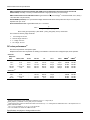
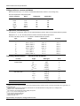
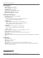
Model 2182A
Instrument specifications
Keithley Instruments, Inc.
28775 Aurora Road
Cleveland, Ohio 44139
1-888-KEITHLEY
http://www.keithley.com
Specification conditions
This document contains specifications and supplemental information for the Model 2182A Nanovoltmeter. Specifications are
the standards against which the Model 2182A is tested. Upon leaving the factory, the Model 2182A meets these
specifications. Supplemental and typical values are nonwarranted, apply at 23 °C, and are provided solely as useful
information.
Measurement accuracies are specified at the Model 2182A terminals under these conditions:
1.
2.
3.
4.
23 °C ± 5 °C, < 80 percent relative humidity
After a 2½ hour warm-up period
A/D autozero enabled
Properly zeroed local operation using the relative offset (REL) function. If REL is not used, add 100 nV to the range
accuracy.
Voltage specifications
Conditions: 1 PLC with 10 reading digital filter or 5 PLC with 2 reading digital filter.
Accuracy: ±(ppm of reading + ppm of range)
where: ppm = parts per million, for example, 10ppm = 0.001%
Accuracy
Channel 1
Range
Resolution
2,3,4
10.000000 mV
100.00000 mV
1.0000000 V
10.000000 V
4
100.00000 V
Channel 2
1 nV
10 nV
100 nV
1 μV
10 μV
1
Input
resistance
24 Hour
TCAL ±1°C
>10 GΩ
>10 GΩ
>10 GΩ
>10 GΩ
10 MΩ±1%
20 + 4
10 + 3
7+2
5
2+1
10 + 3
90 Day
TCAL ±5°C
40 + 4
25 + 3
18 + 2
18 + 2
25 + 3
1 Year
2 Year
TCAL ±5°C TCAL ±5°C
50 + 4
30 + 4
25 + 2
25 + 2
35 + 4
Temperature
coefficient
0 – 18°C &
28°– 50°C
60 + 4
40 + 5
32 + 3
32 + 3
52 + 5
(1 + 0.5)/°C
(1 + 0.2)/°C
(1 + 0.1)/°C
(1 + 0.1)/°C
(1 + 0.5)/°C
6,7
100.00000 mV
1.0000000 V
10.000000 V
10 nV
100 nV
1 μV
>10 GΩ
>10 GΩ
>10 GΩ
10 + 6
7+2
5
2+1
25 + 6
18 + 2
18 + 2
30 + 7
25 + 2
25 + 2
40 + 7
32 + 3
32 + 3
(1 + 1)/°C
(1 + 0.5)/°C
(1 + 0.5)/°C
Channel 1/Channel 2 ratio:
For input signals ≥1% of the
range, ratio accuracy =
Channel 1 Reading + Channel 1 Accuracy
Channel 1 Reading
−
Channel 2 Reading − Channel 2 Accuracy Channel 2 Reading
1
Relative to calibration accuracy.
With Analog Filter on, add 20 ppm of reading to the listed specification.
3
When properly zeroed using the relative offset (REL) function. If REL is not used, add 100 nV to the range accuracy.
4
Specifications include the use of the ACAL function. If ACAL is not used, add 9 ppm of reading/°C from TCAL to the listed specification. TCAL is
the internal temperature stored during ACAL.
5
For 5 PLC with 2-reading Digital Filter. Use ±(4 ppm of reading + 2 ppm of range) for 1 PLC with 10-reading Digital Filter.
6
Channel 2 must be referenced to Channel 1. Channel 2 HI must not exceed 125% (referenced to Channel 1 LO) of the range selected for
Channel 2.
7
For Low Q mode On, add the following to DC noise and range accuracy at stated response time: 200 nV p-p @ 25 s, 500 nV p-p @ 4.0 ,
1.2 μV p-p @ 1 s, and 5 μV p-p @ 85 ms.
2
Specifications are subject to change without notice
SPEC-2182 Rev. D / October 2013
*PSPEC-2182AD*
1 of 6
Model 2182A Instrument specifications
DELTA (hardware-triggered coordination with 24XX series or 622X series current sources for low noise R
measurement): accuracy = accuracy of selected Channel 1 range plus accuracy of I source range
8
DELTA measurement noise with 6220 or 6221: Typical 3nVRMS/√Hz (10 mV range) . 1 Hz achieved with 1 PLC, delay =
1 ms, RPT filter = 23 (20 if 50 Hz)
PULSE-MODE (with 6221): Line synchronized voltage measurements within current pulses from 50 µs to 12 ms, pulse
repetition rate up to 12 Hz
9
Pulse measurement noise: Typical RMS noise, RDUT < 10 ohms :
VRMS =
C
meas_time ∗ �pulse_avg_count
where: meas_time (seconds) = pulse width – pulse_meas_delay in 33 µs increments
The constant C varies by range as follows:
• 10 mV range: 0.16 nV*s
• 100 mV range: 0.60 nV*s
• 1 V range: 2.2 nV*s
• 10 V range: 18 nV*s
DC noise performance 10
DC noise is expressed in volts peak-to-peak.
Response time is the time required for the reading to be settled in noise levels from a stepped input, 60 Hz operation.
Channel 1
RANGE
Response
10 mV
Time
NPLC, Filter
25.0 s
4.0 s
1.0 s
667 ms
60 ms
Channel 2
25.0 s
4.0 s
1.0 s
85 ms
100 mV
1V
10 V
100 V
NMRR
11
CMRR
12
5, 75
5, 10
1, 18
1, 10 or 5, 2
1, Off
6 nV
15 nV
25 nV
35 nV
70 nV
20 nV
50 nV
175 nV
250 nV
300 nV
75 nV
150 nV
600 nV
650 nV
700 nV
750 nV
1.5 μV
2.5 μV
3.3 μV
6.6 μV
75 μV
75 μV
100 μV
150 μV
300 μV
110 dB
100 dB
95 dB
90 dB
60 dB
140 dB
140 dB
140 dB
140 dB
140 dB
5, 75
5, 10
1, 10 or 5, 2
1, Off
-
150 nV
150 nV
175 nV
425 nV
200 nV
200 nV
400 nV
1 μV
750 nV
1.5 μV
2.5 μV
9.5 μV
-
110 dB
100 dB
90 dB
60 dB
140 dB
140 dB
140 dB
140 dB
6,7
Applies to measurements of room temperature resistances <10 Ω, Isource range ≤ 20 µA
meas_time(sec) = pulsewidth – source_delay in 33 µs increments
10
Noise behavior using 2188 Low Thermal Short after 2.5 hour warm-up. ±1 °C. Analog Filter off. Observation time = 10X response time or 2
minutes, whichever is less.
11
For LSYNC On, line frequency ±0.1 %. If LSYNC Off, use 60 dB.
12
For 1 kΩ unbalance in LO lead. AC CMRR is 70 dB.
8
9
Specifications are subject to change without notice
SPEC-2182 Rev. D / October 2013
2 of 6
Model 2182A Instrument specifications
Voltage noise vs. source resistance
After 2.5 hour warm-up, ±1 °C, 5 PLC, 2 minute observation time, Channel 1 10 mV range only.
DC noise expressed in volts peak-to-peak.
Source resistance
Noise
Analog filter
Digital filter
0Ω
100 Ω
1 kΩ
10 kΩ
100 kΩ
1 MΩ
6 nV
8 nV
15 nV
35 nV
100 nV
350 nV
Off
Off
Off
Off
On
On
100
100
100
100
100
100
Temperature (thermocouples)
For Channel 1 or Channel 2, add 0.3 °C for external reference junction. Add 2 °C for internal reference junction.
Displayed in °C, °F, or K. Accuracy based on ITS-90, exclusive of thermocouple errors.
Accuracy is 90 day/1 year 23 °C ±5 °C relative to simulated reference junction.
Type
Range
Resolution
Accuracy
J
K
N
T
E
R
S
B
-200 to +760 °C
-200 to +1372 °C
-200 to +1300 °C
-200 to +400 °C
-200 to +1000 °C
0 to +1768 °C
0 to +1768 °C
+350 to +1820 °C
0.001 °C
0.001 °C
0.001 °C
0.001 °C
0.001 °C
0.1 °C
0.1 °C
0.1 °C
±0.2 °C
±0.2 °C
±0.2 °C
±0.2 °C
±0.2 °C
±0.2 °C
±0.2 °C
±0.2 °C
Operating characteristics 13,14 60 Hz (50 Hz) operation
Function
Digits
Readings/s
PLCs
DCV Channel 1, Channel 2,
Thermocouple
7.5
15,16
7.5
16,17
6.5
16,17,18
6.5
15,16
5.5
15,16,19
4.5
7.5
15,16
7.5
17
6.5
17,18
6.5
15
5.5
15
4.5
6.5
3 (2)
6 (4)
18 (15)
45 (36)
80 (72)
115 (105)
1.5 (1.3)
2.3 (2.1)
8.5 (7.5)
20 (16)
30 (29)
41 (40)
20
47 (40)
5
5
1
1
0.1
0.01
5
5
1
1
0.1
0.01
1
Channel 1/Channel 2, (Ratio), Delta
with 24XX, Scan
Delta with 622X
13
Speeds are for 60 Hz (50 Hz) operation using factory default operating conditions (*RST). Autorange Off, Display Off, Trigger Delay = 0,
Analog Output Off.
Speeds include measurements and binary data transfer out of the GPIB interface. Analog Filter On, 4 readings/s max.
15
Sample count = 1024, Auto Zero Off.
16
For Channel 2 Low Q mode Off, reduce reading rate by 30%.
17
For LSYNC On, reduce reading rate by 15%.
18
Front Auto Zero Off, Auto Zero Off.
19
10 mV range, 80 readings/s max.
20
Display off, delay 1 ms
14
Specifications are subject to change without notice
SPEC-2182 Rev. D / October 2013
3 of 6
Model 2182A Instrument specifications
System speeds13,21
14
Range change time : <40 ms (<50 ms)
14
Function change time : <45 ms (<55 ms)
14
AUTORANGE time : <60 ms (<70 ms)
ASCII reading to RS-232 (19.2K baud): 40/s (40/s)
19
Maximum internal trigger rate : 120/s (120/s)
19
Maximum external trigger rate : 120/s (120/s)
Measurement characteristics
A-D linearity: ±(0.8 ppm of reading + 0.5 ppm of range)
Front AUTOZERO off error
10 mV – 10 V: Add ±(8 ppm of reading + 500 μV) for <10 minutes and ±1 °C
NOTE: Offset voltage error does not apply for Delta Mode.
AUTOZERO off error
10 mV: Add ±(8 ppm of reading + 100 nV) for <10 minutes and ±1 °C
100 mV – 100 V: Add ±(8 ppm of reading + 10 μV) for <10 minutes and ±1 °C
NOTE: Offset voltage error does not apply for Delta Mode.
Input impedance
10 mV – 10 V: >10 GΩ, in parallel with <1.5 nF (Front Filter ON)
10 mV – 10 V: >10 GΩ, in parallel with <0.5 nF (Front Filter OFF)
100 V:
10 MΩ ±1 %
22
DC input bias current : <60 pA @ 23 °C, –10 V to 5 V <120 pA @ 23 °C, 5 V to 10 V
Common mode current: <50 nA p-p at 50 Hz or 60 Hz
Input protection: 150 V peak to any terminal, 70 V peak Channel 1 LO to Channel 2 LO
Channel isolation: >10 GΩ
Earth isolation: 350 V peak, >10 GΩ and <150 pF any terminal to earth. Add 35 pF/ft with Model 2107 Low Thermal Input
Cable
Analog output
Maximum Output: ±1.2 V
Accuracy: ±(0.1 % of output + 1 mV)
Output resistance: 1 kΩ ±5 %
-9
6
Gain: Adjustable from 10 to 10 ; with gain set to 1, a full range input will produce a 1 V output
Output REL: Selects the value of input that represents 0 V at output; the reference value can be either a programmed
value or the value of the previous input
21
22
Auto Zero Off, NPLC = 0.01.
Analog Filter On, Digital Filter On.
Specifications are subject to change without notice
SPEC-2182 Rev. D / October 2013
4 of 6
Model 2182A Instrument specifications
Triggering and memory
Window filter sensitivity: 0.01 %, 0.1 %, 1 %, 10 %, or full scale range (none)
Reading hold sensitivity: 0.01 %, 0.1 %, 1 %, or 10 % of reading
Trigger delay: 0 to 99 hours (1 ms step size)
External trigger delay: 2 ms + <1 ms jitter with auto zero off, trigger delay = 0
Memory size: 1024 readings
Math functions
Rel, Min/Max/Average/Std. Dev/Peak-to-Peak (of stored reading), Limit Test, %, and mX+b with user-defined units
displayed
Remote interface
Keithley 182 emulation
GPIB (IEEE-488.2) and RS-232C
SCPI (Standard Commands for Programmable Instruments)
General specifications
Power supply: 100 V/120 V/220 V/240 V
Line frequency: 50 Hz, 60 Hz, and 400 Hz, automatically sensed at power-up
Power consumption: 22 VA
Magnetic field density: 10 mV range 4.0 s response noise tested to 500 gauss
Operating environment: Specified for 0 °C to 50 °C; specified to 80% RH at 35 °C
Storage environment: –40 °C to 70 °C
EMC: Complies with European Union Directive 89/336/EEC (CE marking requirement), FCC part 15 class B, CISPR 11,
IEC 801-2, IEC-801-3, IEC 801-4
Safety: Complies with European Union Directive 73/23/EEC (low voltage directive); meets EN61010-1 safety standard,
Installation category I
Vibration: MIL-T-28800E Type III, Class 5.
Warm-up: 2.5 hours to rated accuracy
Dimensions
Rack Mounting: 89 mm high x 213 mm wide x 370 mm deep (3.5 in x 8.375 in x 14.563 in)
Bench Configuration (with handles and feet): 104 mm high x 238 mm wide x 370 mm deep
(4.125 in x 9.375 in x 14.563 in)
Shipping weight: 5 kg (11 lb)
Specifications are subject to change without notice
SPEC-2182 Rev. D / October 2013
5 of 6
Model 2182A Instrument specifications
Supplied accessories
2107-4: Low Thermal Input Cable with spade lugs, 1.2 m (4 ft)
User manual, service manual, contact cleaner, line cord, alligator clips
Available accessories
2107-30:
Low Thermal Input Cable with spade lugs, 9.1 m (30 ft)
2182-KIT:
Low Thermal Connector with strain relief
2187-4
Low Thermal Test Lead Kit
2188:
Low Thermal Calibration Shorting Plug
4288-1:
Single Fixed Rack Mount Kit
4288-2:
Dual Fixed Rack Mount Kit
7007-1:
Shielded GPIB Cable, 1 m (3.2 ft)
7007-2:
Shielded GPIB Cable, 2 m (6.5 ft)
7009-5:
Shielded RS-232 Cable 1.5 m (5 ft)
8501-1:
Trigger-Link Cable 1 m (3.2 ft)
8501-2:
Trigger-Link Cable 2 m (6.5 ft)
8503:
Trigger-Link Cable to 2 Male BNC Connectors
Specifications are subject to change without notice
SPEC-2182 Rev. D / October 2013
6 of 6