1
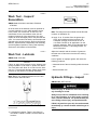
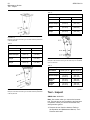
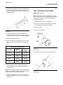
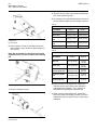
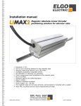
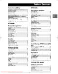
MAINTENANCE INTERVALS
Operation and Maintenance
Manual Excerpt
© 2010 Caterpillar
All Rights Reserved
®
®
SEBU7921-03
July 2007
Operation and
Maintenance
Manual
H35D S, H45D S, H55D S and H65D S
Hydraulic Hammers
BXH1-Up (H35D S flat-top)
BXJ1-Up (H45D S flat-top)
FTF1-Up (H55D S flat-top)
FTS1-Up (H65D S flat-top)
BWM1-Up (H55D S pin-on)
BYT1-Up (H65D S pin-on)
46
Maintenance Section
Maintenance Interval Schedule
SEBU7921-03
i02794753
Maintenance Interval Schedule
SMCS Code: 6700-041; 7519
Every 2 Service Hours or 4 Times Daily
Work Tool - Lubricate ............................................ 47
Daily
Mounting Bracket - Inspect ................................... 49
Initial 50 Service Hours
Mounting Bracket Bolts - Tighten .......................... 49
Side Plate Bolts - Tighten ..................................... 49
Every 50 Service Hours or Weekly
Hydraulic Fittings - Inspect ...................................
Tool - Inspect ........................................................
Tool - Remove and Install .....................................
Tool Retaining Pins - Inspect/Replace ..................
Tool Bushing - Inspect/Replace ............................
47
50
51
53
54
Every 1000 Service Hours or 1 Year
Work Tool - Inspect/Recondition ........................... 47
SEBU7921-03
47
Maintenance Section
Work Tool - Inspect/Recondition
i02808879
Work Tool - Inspect/
Recondition
SMCS Code: 6333-020; 6333-040; 6700-020;
6700-040
All of the seals in the hammer must be replaced on
a yearly schedule or every 1000 machine service
hours, which ever comes first. At this time, the
membranes for the accumulators must also be
replaced. Inspect all of the wear parts. You must
replace all of the damaged parts or the parts that are
worn. You must make sure that the accumulators are
charged to the correct pressure. Refer to the Service
Manual, “Specifications, Disassembly and Assembly,
and the Systems Operation, Testing and Adjusting”
Sections for information on the hammer.
i02798571
Work Tool - Lubricate
SMCS Code: 6700-086
NOTICE
Failure to apply down pressure on the hammer tool
during lubrication could result in piston seal failure.
This seal failure will allow oil to leak from the hammer tool. To avoid seal damage, always apply down
pressure on the hammer tool during lubrication.
Note: Before you install the hammer tool, the tool
shank must be well lubricated.
Illustration 68
g01161963
Note: The fitting has been marked with the film that
is shown in Illustration 68.
2. Apply 10 to 15 strokes from the grease gun
to the tool bushings and the hammer tool.
Caterpillar strongly recommends the use of
130-6951 Grease for all applications on the
hydraulic hammers. Refer to the Operation and
Maintenance Manual, “Lubricating Grease” for
more information.
Adjust the intervals and the amount of grease to
the wear rate of hammer tool and to the working
conditions.
Lack of grease or improper grease will cause the
following problems:
• Abnormal wear of the tool bushing and the hammer
tool
• Broken hammer tool
i02796809
Hydraulic Fittings - Inspect
SMCS Code: 5057-040-X6
Personal injury or death can result from improperly checking for a leak.
Always use a board or cardboard when checking
for a leak. Escaping air or fluid under pressure,
even a pin-hole size leak, can penetrate body tissue causing serious injury, and possible death.
Illustration 67
g01355826
typical example
1. Lubricate the hammer. There is one fitting on
the H35D S, H45D S, H55D S, and the H65D S
hammer.
If fluid is injected into your skin, it must be treated
immediately by a doctor familiar with this type of
injury.
48
Maintenance Section
Hydraulic Fittings - Inspect
SEBU7921-03
NOTICE
For maximum durability in demanding applications, always use Caterpillar High Vibration Hose Couplings.
Refer to Parts Manual, SEBP4160 for additional information on Caterpillar High Vibration Hose Couplings.
1. Check the hydraulic fittings (1) and (3) for damage
or leaks.
2. Check the supply hoses (2) for damage or wear.
3. Check all of the clamps on the host machine.
Illustration 69
g01396898
Typical example of hydraulic fittings on an MHE arrangement for
the H35D S flat-top, H45D S flat-top, H55D S flat-top and H65D
S flat-top hammers
4. Repair any damaged parts or worn parts before
you operate the hammer. Replace any damaged
parts or worn parts before you operate the
hammer. Repair any leaks before you operate the
hammer.
Note: The hydraulic ports are located on the
operator’s side of the hammer for the MHE
arrangement. The supply port is located on the top
on the H35D S flat-top and H45D S flat-top hammer.
The supply port is located on the right on the H55D S
flat-top and H65D S flat-top hammer. The supply port
is marked as the “IN” port. The return port is located
on the bottom on the H35D S flat-top and H45D S
flat-top hammer. The return port is located on the left
on the H55D S flat-top and H65D S flat-top hammer.
The return port is marked as the “OUT” port.
Illustration 70
g01161971
Typical example of hydraulic fittings on an MHE arrangement or
BHL arrangement for the H55D S pin-on, H55D S flat-top, H65D S
pin-on or H65D S flat-top hammers
Illustration 71
g01161972
Typical example of hydraulic fittings on an SSL or MTL for the
H55D S pin-on or H65D S pin-on hammers
Note: The hydraulic ports are located on the top of
the hammer for the SSL / MTL arrangements . The
supply port is located on the right. The supply port is
marked as the “IN” port. The return port is located on
the left. The return port is marked as the “OUT” port.
SEBU7921-03
49
Maintenance Section
Mounting Bracket Bolts - Tighten
i02796812
i02326114
Mounting Bracket Bolts Tighten
Mounting Bracket - Inspect
SMCS Code: 7079-527-BK; 7079-527-BC
S/N: BWM1-Up
S/N: FTF1-Up
S/N: BYT1-Up
SMCS Code: 7079
S/N: BXH1-Up
SSL - MTL Arrangement
S/N: BXJ1-Up
S/N: FTS1-Up
Illustration 73
g01400999
Illustration 72
H35D S flat-top, H45D S flat-top, H55D S flat-top and H65D S
flat-top
Inspect the bolts (1) for the mounting bracket. If
necessary, tighten the bolts (1) for the mounting
bracket to the proper torque. Refer to table 8 for the
proper torque value.
Sales Model
Bolt
Bolt Torque
8T-4141
530 ± 70 N·m
(391 ± 52 lb ft)
8T-4187
530 ± 70 N·m
(391 ± 52 lb ft)
7X-2564
530 ± 70 N·m
(391 ± 52 lb ft)
H35D S flat-top
H45D S flat-top
H55D S flat-top
(1)
H65D S flat-top
(1)
Inspect upper angled plate (1) and ensure that the
plate is not bent or otherwise damaged. Inspect holes
(2) for wear and for damage. Inspect lower angled
plate (3) and ensure that the plate is not bent or
otherwise damaged. Consult your Caterpillar dealer if
any wear is suspected or any damage is suspected.
i02797037
Side Plate Bolts - Tighten
Table 8
H55D S flat-top
g01162046
Some models use these bolts.
SMCS Code: 6333-079-BC
Inspect the socket head bolts for the side plates for
the proper torque. If necessary, tighten the socket
head bolts to the proper torque. Refer to illustrations
74 and 76 and tables 9, 10 and 11for the proper
torque value.
Note: Tighten the socket head bolts in a cross pattern
in order to ensure correct alignment of the housing
and the dampening elements. Coat the threads on
the socket head bolts at the time of assembly.
50
Maintenance Section
Tool - Inspect
SEBU7921-03
Table 10
Torque Values for Silenced Hammer
Sales Model
H55D S flat-top
H65D S flat-top
Bolt
263-6016
174-6393
Nominal Torque
175 N·m
(129 lb ft)
340 N·m
(251 lb ft)
Maximum
Torque
205 N·m
(151 lb ft)
380 N·m
(280 lb ft)
Minimum
Torque
145 N·m
(107 lb ft)
300 N·m
(221 lb ft)
g01275843
Illustration 74
Example of the silenced housing on the H35D S flat-top and H45D
S flat-top hammer
Table 9
Torque Values for Silenced Hammer
Sales Model
H35D S flat-top
H45D S flat-top
Bolt
216-8310
223-8990
Nominal Torque
175 N·m
(129 lb ft)
175 N·m
(129 lb ft)
Maximum
Torque
205 N·m
(151 lb ft)
205 N·m
(151 lb ft)
Illustration 76
Minimum
Torque
145 N·m
(107 lb ft)
145 N·m
(107 lb ft)
Example of the silenced housing on the H55D S pin-on and H65D
S pin-on hammers
g01162082
Table 11
Torque Values for Silenced Hammer
Sales Model
Illustration 75
H55D S pin-on
H65D S pin-on
Bolt
263-6016
174-6393
Nominal Torque
175 N·m
(129 lb ft)
340 N·m
(251 lb ft)
Maximum
Torque
205 N·m
(151 lb ft)
380 N·m
(280 lb ft)
Minimum
Torque
145 N·m
(107 lb ft)
300 N·m
(221 lb ft)
g01397237
Example of the silenced housing on the H55D S flat-top and H65D
S flat-top hammer
i02798624
Tool - Inspect
SMCS Code: 6826-040
Note: Use caution when you remove the hammer
tool. The tool can be very hot after the tool has been
in operation. When you remove the hammer tool,
wear protective gloves.
1. Remove the tool from the hammer. Refer to
the Operation and Maintenance Manual, “Tool Remove and Install”.
SEBU7921-03
51
Maintenance Section
Tool - Remove and Install
2. If necessary, grind the burrs off the hammer tool.
Make sure that you remove the burrs from the
notch for the retaining pin. Remove the burrs from
the retaining pin.
i02797434
Tool - Remove and Install
SMCS Code: 6826-010
Note: Use caution when you remove the hammer
tool. The tool can be very hot after the tool has been
in operation. When you remove the hammer tool,
wear protective gloves.
1. Position the hammer on level ground.
2. Put the host machine’s transmission in neutral.
The parking brake should be engaged.
3. Stop the engine.
4. Exit the host machine.
g00678194
Illustration 77
3. Check the hammer tool for wear. When you
measure the wear of the tool, you must measure
the part of the tool (A) that is in the tool bushings.
4. Measure the dimension (B).
5. Refer to Table 12 for the dimension of a new tool.
Refer to Table 12 for the minimum diameter of a
tool.
Table 12
Wear Limits for Hammer Tools
Sales Model
Diameter of
New Tool
Minimum
Diameter of
Tool
H35D S
40 mm
(1.57 inch)
38 mm
(1.50 inch)
H45D S
48 mm
(1.89 inch)
46 mm
(1.81 inch)
H55D S
56 mm
(2.20 inch)
54 mm
(2.13 inch)
H65D S
65 mm
(2.56 inch)
63 mm
(2.48 inch)
Illustration 78
g01162248
typical example
5. Remove plug (1) from the side of the hammer.
6. You must replace the tool if dimension (B) is
smaller than the minimum diameter of the tool for
your hammer.
Note: Do not weld on a hammer tool. Welding on the
hammer tool causes cracks in the hammer tool. The
cracks will cause the hammer tool to fail.
7. Inspect the hammer tool for cracks. If there are
cracks in the hammer tool, you must replace the
hammer tool.
Illustration 79
typical example
g01162250
52
Maintenance Section
Tool - Remove and Install
SEBU7921-03
8. Remove tool (3). When you remove the hammer
tool, wear protective gloves.
9. If necessary, use a suitable lifting device to remove
the tool. Refer to table 14 for the weight of the tool.
Table 13
Weights of Small Hammer Tools
Sales Model
H35D S
H45D S
Moil Tool
3.4 kg (7.5 lb)
5.8 kg (12.8 lb)
Chisel Tool
3.5 kg (7.7 lb)
5.9 kg (13 lb)
Parallel Spade
Tool
3.5 kg (7.7 lb)
5.9 kg (13 lb)
typical example
Transverse Spade
Tool
3.5 kg (7.7 lb)
5.9 kg (13 lb)
6. Insert a punch in hole (Y) and strike the punch
with a mallet in order to remove retaining pin (2)
and Tool (3).
Compacting Plate
8.5 kg (18.7 lb)
9.9 kg (21.8 lb)
Illustration 80
g01162251
Note: Do not hesitate in striking the punch with
significant force in order to remove the retaining
pin.
Table 14
Weights of Small Hammer Tools
Sales Model
H55D S
H65D S
9.10 kg (20 lb)
13.6 kg
(30 lb)
Chisel Tool
9.32 kg (20.5 lb)
14 kg
(30.9 lb)
Parallel Spade Tool
9.69 kg (21.4 lb)
12.9 kg
(28.4 lb)
Transverse Spade
Tool
9.74 kg (21.5 lb)
12.9 kg
(28.4 lb)
Compacting Plate
23 kg (50.7 lb)
26.2 kg
(57.8 lb)
Moil Tool
Illustration 81
g01401123
7. Remove retaining ring (4).
10. After you have removed the tool, inspect the
hammer tool for wear. Refer to the Operation
and Maintenance Manual, “Tool - Inspect” for
information on inspecting the hammer tool.
11. After you have removed the tool, inspect the
seal in the lower tool bushing for wear. You must
replace the seal if the seal is worn or if the seal is
damaged.
Illustration 82
typical example
g01162252
SEBU7921-03
53
Maintenance Section
Tool Retaining Pins - Inspect/Replace
Installation of Tool
5. Install retaining ring (4).
6. Install pin (2) to tool (3).
Illustration 83
g01162252
typical example
Illustration 86
1. Clean tool (3).
typical example
2. Apply lubricant 130-6951 Grease (Hammer
Paste) to tool (3).
7. Install plug (1).
3. Install tool (3).
g01162248
i02552060
Tool Retaining Pins Inspect/Replace
SMCS Code: 6826-040; 6826-510
Illustration 84
g01162251
typical example
4. Apply lubricant 130-6951 Grease (Hammer
Paste) to pin (2).
Illustration 87
g01162425
typical example
1. Remove pin (1) from the hammer. Refer to
Operation and Maintenance Manual, “Tool Remove and Install” for additional information on
removing the pin.
Illustration 85
g01401123
54
Maintenance Section
Tool Bushing - Inspect/Replace
SEBU7921-03
i02797436
Tool Bushing - Inspect/Replace
SMCS Code: 6826-040-GY; 6826-528
Illustration 88
g01162427
typical example
2. Inspect the pin for wear or for cracks.
3. If the pin is cracked, you must replace the pin.
g01162452
Illustration 90
typical example
1. Remove tool (1). Refer to Operation and
Maintenance Manual, “Tool - Remove and Install”
for information on the removal procedure.
2. Clean the inside of tool bushing (2). Inspect the
inside bore of the tool bushing for wear.
Illustration 89
g01162431
typical example
4. Inspect the retaining ring (2) for wear or for
damage. The retaining ring is located inside the
hammer housing. Replace the retaining ring if
the retaining ring is worn or if the retaining ring is
damaged. Refer to Service Manual, RENR4478
for additional information on replacing the retaining
ring.
g01277588
Illustration 91
typical example
3. You must replace the tool bushing if the tool
bushing has too much wear. Refer to Table 15 for
the dimensions.
Table 15
Tool Bushing Wear Limits
Sales Model
Maximum Dimension (A)
H35D S
43 mm (1.7 inch)
H45D S
51 mm (2 inch)
H55D S
59 mm (2.3 inch)
H65D S
68 mm (2.7 inch)
SEBU7921-03
4. Inspect seal (3). Replace seal (3) if the seal is
worn or if the seal is damaged.
5. Install tool (1). Refer to Operation and
Maintenance Manual, “Tool - Remove and Install”
for information on the installation procedure.
55
Maintenance Section
Tool Bushing - Inspect/Replace