1
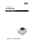
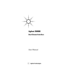
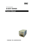
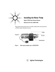
Installation Guide
Split/Splitless Capillary Inlet
Accessory 19251A
© Agilent Technologies 2000
Safety Information
Safety Symbols
All Rights Reserved. Reproduction,
adaptation, or translation without
permission is prohibited, except as allowed
under the copyright laws.
The Agilent Technologies Split/Splitless
Capillary Inlet meets the following IEC
(International Electrotechnical Commission)
classifications: Safety Class 1, Transient
Overvoltage Category II, and Pollution
Degree 2.
Warnings in the manual or on the
instrument must be observed during all
phases of operation, service, and repair of
this instrument. Failure to comply with these
precautions violates safety standards of
design and the intended use of the
instrument. Agilent Technologies assumes
no liability for the customer’s failure to
comply with these requirements.
Part number 19251-90117
First Edition, DEC 2000
Replaces Part No. 19251-90110 Operating
and Service Manual.
HP® is a registered trademark of
Hewlett-Packard Co.
Printed in USA
This unit has been designed and tested in
accordance with recognized safety
standards and designed for use indoors. If
the instrument is used in a manner not
specified by the manufacturer, the
protection provided by the instrument may
be impaired. Whenever the safety protection
of the Agilent 19251 has been compromised,
disconnect the unit from all power sources
and secure the unit against unintended
operation.
Refer servicing to qualified service
personnel. Substituting parts or performing
any unauthorized modification to the
instrument may result in a safety hazard.
Disconnect the AC power cord before
removing covers. The customer should not
attempt to replace the battery or fuses in
this instrument.
WARNING
A warning calls attention to a condition or
possible situation that could cause injury to
the user.
CAUTION
A caution calls attention to a condition or
possible situation that could damage or
destroy the product or the user’s work.
Sound Emission Certification for Federal
Republic of Germany
Sound pressure Lp < 68 dB(A)
During normal operation
At the operator position
According to ISO 7779 (Type Test)
Schallemission
Schalldruckpegel LP < 68 dB(A)
Am Arbeitsplatz
Normaler Betrieb
Nach DIN 45635 T. 19 (Typprüfung)
Agilent Technologies, Inc.
2850 Centerville Road
Wilmington, DE 19808-1610
USA
Installing the Split/Splitless Capillary Inlet
Accessory 19251A
WARNING
Hydrogen (H2) is flammable and an explosion hazard when confined in an
enclosed space (for example, the oven). In ANY application using H2, turn off
the supply at its source before working on the instrument.
Caution
The insulation on the GC is made of refractory ceramic fibers. Ventilate your
work area. Wear long sleeves, gloves, safety glasses, and a disposable dust/
mist respirator. Dispose of insulation in a sealed plastic bag.
Preparing the Instrument
WARNING
Hazardous voltages are present in the instrument whenever the power cord
is connected. Avoid a potentially dangerous shock hazard by disconnecting
the power cord before working on the instrument.
1.
Set the main power line switch to the off position.
Red O visible
OFF
Copyright© 2000
Agilent Technologies
Printed in USA Dec 2000
Agilent Part No. 19251-90117
ON
Installing the Split/Splitless Capillary Inlet Accessory 19251A
Preparing the Instrument
2.
Disconnect the power cable from its receptacle.
3.
Allow time for the oven and heated zones to cool.
4.
When the heated zones are cool, turn off all gas supplies at the source.
5.
Remove the injection port cover by grasping its back edge and lifting it
upward. If an autosampler is installed, the injection port cover will not
be present.
Injection port cover
Top cover
Lid shaft
Press here to
free cover
1/4-inch screw
and washer
6.
2
If an autosampler is installed on the instrument, it will be necessary to
remove it and its mounting bracket to allow removal of the left side
cover.
a.
Remove the autosampler tray from its mounting bracket by
simultaneously lifting and turning the two tray locks that hold it in
position, then sliding the tray away from the instrument.
b.
Lift the autosampler tray from its mounting bracket and set it aside.
c.
Remove the autosampler bracket by removing the six screws
securing it to the instrument.
Installing the Split/Splitless Capillary Inlet Accessory 19251A
Preparing the Instrument
7.
Remove the two screws securing the left side panel along its bottom
edge.
Left side panel
Screws
8.
Slide the left side panel towards the rear of the instrument and lift.
9.
Remove the electronics carrier top cover by grasping it at the rear and
lifting upwards until its catch releases, then pull it towards the rear of
the instrument.
10. Remove the right side panel by removing four screws, two each along its
top and bottom edges.
Screws
Screws
Right side panel
3
Installing the Split/Splitless Capillary Inlet Accessory 19251A
Preparing the Instrument
11. Remove the back cover of the instrument by removing four screws and
sliding the cover off the rear of the instrument.
Screws
Screws
4
Installing the Split/Splitless Capillary Inlet Accessory 19251A
Installing the Inlet
Installing the Inlet
Caution
The insulation on the GC is made of refractory ceramic fibers (RCF).
Ventilate your work area. Wear long sleeves, gloves, safety glasses, and a
disposable dust/mist respirator. Dispose of insulation in a sealed plastic
bag.
1.
If present, remove the cover plate from the inlet mounting location.
Remove enough insulation to allow the injection port to fit.
Inlet cover plates
B position
A position
2.
Plug the opening at the inlet bottom to prevent contamination.
5
Installing the Split/Splitless Capillary Inlet Accessory 19251A
Installing the Inlet
Caution
3.
Install the inlet from the top of the oven. Secure the inlet with two M4
screws.
4.
Remove the flow-control label plate in the injection port A or B location.
The plate is glued in place and is removed by pushing it firmly through
openings in the back of the flow panel to get it started, then pull it free.
5.
Place the provided self-adhesive split/splitless flow plate in the space
where flow-control components for the inlet are to be installed.
Avoid sharp bends in the tubing. A tight bend radius may crimp the tubing.
6.
6
There are two threaded studs on the back of the main flow panel for
installing the inlet flow module. Place the flow module assembly on the
Installing the Split/Splitless Capillary Inlet Accessory 19251A
Installing the Inlet
studs, securing it with a M4 hex nut on each stud. Use a 7-mm nut
driver to tighten the nuts.
Split/Splitless Capillary Flow module
Carrier gas inlet fitting
WARNING
Hydrogen (H2) is flammable and an explosion hazard when confined in an
enclosed space (for example, the oven). In ANY application using H2, turn off
the supply at its source before working on the instrument.
7.
Using 1/8-inch OD copper tubing, connect the carrier gas supply tube to
the carrier gas inlet fitting.
8.
Route the heater and sensor leads through the instrument rear plastic
tray to the main circuit board. Heater and sensor wires must be
connected to matching heated zones (INJ A sensor on P7 and INJ A
heater on J9 or INJ B sensor on P7 and INJ B heater on J9). Connect the
heater and sensor leads to the instrument main circuit board as follows:
7
Installing the Split/Splitless Capillary Inlet Accessory 19251A
Installing the Inlet
9.
Agilent 4890 Series and 5890 SERIES II: Connect the sensor leads
(white) to P7. Connect the heater leads (red) to J9. Connect the purge
valve leads (orange, red) to P8 (polarity in this case does not matter).
4890 Series and 5890 SERIES II Main Circuit Board
Sensors
Position 7 & 8 = Inj A position
Position 9 & 10 = Inj B position
Position 3 & 4 = Purge A
Position 5 & 6 = Purge B
P7
White
P8
Orange and red
Heaters
J9
Position 5 & 6 = Inj A position
Position 3 & 4 = Inj B position
Red
8
Installing the Split/Splitless Capillary Inlet Accessory 19251A
Installing the Inlet
10. Agilent 5890A: Connect the sensor leads (white) to J7. Connect the
heater leads (red) to J9. Connect the purge valve leads (orange, red) to
J8 (polarity in this case does not matter).
5890A MainCircuit Board
Sensors
White
Purge A
Purge B
Orange and Red
Heaters
J9
Red
9
Installing the Split/Splitless Capillary Inlet Accessory 19251A
Restore the GC to Operation
11. Install the lower insulation cup and insulation over the inlet inside the
oven. Secure the cup using two M4 screws provided.
Restore the GC to Operation
For additional information on the steps below, see the Agilent 4890 GC
Operating Manual.
10
1.
Install the column.
2.
Restore carrier gas flow and leak test the new connections.
3.
If the system is leak-free, reinstall the panels and covers. Reconnect the
instrument power cord and restore power.
Printed on recycled paper.
This product is recyclable.
Agilent Technologies, Inc.
Printed in USA Dec 2000
19251-90117