1
TOSHIBA Thermal Printer
B-SX8T SERIES
Owner’s Manual
Mode d’emploi
Bedienungsanleitung
Manual de instrucciones
Gebruikershandleiding
Manuale Utente
Manual do Utilizador
CE Compliance (for EU only)
This product complies with the requirements of EMC and Low Voltage Directives including their
amendments.
VORSICHT:
• Schallemission: unter 70dB (A) nach DIN 45635 (oder ISO 7779)
• Die für das Gerät Vorgesehene Steckdose muß in der Nähe des Gerätes und leicht zugänglich sein.
Centronics is a registered trademark of Centronics Data Computer Corp.
Microsoft is a registered trademark of Microsoft Corporation.
Windows is a trademark of Microsoft Corporation.
As an ENERGY STAR® Partner, TOSHIBA TEC has determined that this
product meets the ENERGY STAR® guidelines for energy efficiency.
-- Outline of the International ENERGY STAR® Office Equipment Program -The International ENERGY STAR® Office Equipment Program is an international program that
promotes energy saving through the penetration of energy efficient computers and other office
equipment. The program backs the development and dissemination of products with functions that
effectively reduce energy consumption. It is an open system in which business proprietors can
participate voluntarily. The targeted products are office equipment such as computers, monitors,
printers, facsimiles, copiers, scanners, and multifunction devices. Their standards and logos are
uniform among participating nations.
ENERGY STAR is a U.S. registered mark.
This equipment has been tested and found to comply with the limits for a Class A digital device,
pursuant to Part 15 of the FCC Rules. These limits are designed to provide reasonable rotection
against harmful interference when the equipment is operated in a commercial environment. This
equipment generates, uses, and can radiate radio frequency energy and, if not installed and sed in
accordance with the instruction manual, may cause harmful interference to radio communications.
Operations of this equipment in a residential area is likely to cause harmful interference in which case
the user will be required to correct the interference at his own expense.
(for USA only)
Changes or modifications not expressly approved by manufacturer for compliance could void the
user’s authority to operate the equipment.
“This Class A digital apparatus meets all requirements of the Canadian Interference-Causing
Equipment Regulations.”
“Cet appareil numérique de la classe A respecte toutes les exigences du Règlement sur le matériel
brouilleur du Canada.”
(for CANADA only)
IP20
< For EU Only >
TOSHIBA TEC Europe Retail Information Systems S.A.
Rue de la Célidée 33 BE-1080 Brussels
Copyright © 2006
by TOSHIBA TEC CORPORATION
All Rights Reserved
570 Ohito, Izunokuni-shi, Shizuoka-ken, JAPAN
TOSHIBA Thermal Printer
B-SX8T SERIES
Owner's Manual
Waste Recycling information for users:
Following information is only for EU-member states:
The use of the crossed-out wheeled bin symbol indicates that this product
may not be treated as general household waste.
By ensuring this product is disposed of correctly you will help prevent
potential negative consequences for the environment and human health, which could
otherwise be caused by inappropriate waste handling of this product. For more detailed
information about the take-back and recycling of this product, please contact your supplier
where you purchased the product.
Safety Summary
ENGLISH VERSION EO1-33057
Safety Summary
Personal safety in handling or maintaining the equipment is extremely important. Warnings and Cautions
necessary for safe handling are included in this manual. All warnings and cautions contained in this manual
should be read and understood before handling or maintaining the equipment.
Do not attempt to effect repairs or modifications to this equipment. If a fault occurs that cannot be rectified
using the procedures described in this manual, turn off the power, unplug the machine, then contact your
authorised TOSHIBA TEC representative for assistance.
Meanings of Each Symbol
This symbol indicates warning items (including cautions).
Specific warning contents are drawn inside the symbol.
(The symbol on the left indicates a general caution.)
This symbol indicates prohibited actions (prohibited items).
Specific prohibited contents are drawn inside or near the symbol.
(The symbol on the left indicates “no disassembling”.)
This symbol indicates actions which must be performed.
Specific instructions are drawn inside or near the z symbol.
(The symbol on the left indicates “disconnect the power cord plug from the outlet”.)
WARNING
Any other than the
specified AC voltage
is prohibited.
Prohibited
Prohibited
Disconnect
the plug.
This indicates that there is the risk of death or serious injury if the
machines are improperly handled contrary to this indication.
Do not use voltages other than
the voltage (AC) specified on the
rating plate, as this may cause
fire or electric shock.
Prohibited
If the machines share the same
outlet with any other electrical
appliances that consume large
amounts of power, the voltage
will fluctuate widely each time
these appliances operate. Be sure
to provide an exclusive outlet for
the machine as this may cause
fire or electric shock.
Do not insert or drop metal,
flammable or other foreign
objects into the machines through
the ventilation slits, as this may
cause fire or electric shock.
Prohibited
Prohibited
If the machines are dropped or
their cabinets damaged, first turn
off the power switches and
disconnect the power cord plugs
from the outlet, and then contact
your authorised TOSHIBA TEC
representative for assistance.
Continued use of the machine in
that condition may cause fire or
electric shock.
Disconnect
the plug.
(i)
Do not plug in or unplug the power
cord plug with wet hands as this
may cause electric shock.
Do not place metal objects or
water-filled containers such as
flower vases, flower pots or mugs,
etc. on top of the machines. If
metal objects or spilled liquid enter
the machines, this may cause fire
or electric shock.
Do not scratch, damage or modify
the power cords. Also, do not
place heavy objects on, pull on, or
excessively bend the cords, as this
may cause fire or electrical shock.
Continued use of the machines in
an abnormal condition such as
when the machines are producing
smoke or strange smells may cause
fire or electric shock. In these
cases, immediately turn off the
power switches and disconnect the
power cord plugs from the outlet.
Then, contact your authorised
TOSHIBA TEC representative for
assistance.
Safety Summary
ENGLISH VERSION EO1-33057
If foreign objects (metal
fragments, water, liquids) enter
the machines, first turn off the
power switches and disconnect
the power cord plugs from the
outlet, and then contact your
authorised TOSHIBA TEC
representative for assistance.
Continued use of the machine in
that condition may cause fire or
electric shock.
Ensure that the equipment is
Connect a
properly grounded. Extension
grounding wire.
cables should also be grounded.
Fire or electric shock could
occur on improperly grounded
equipment.
Disconnect
the plug.
Disconnect
the plug.
CAUTION
No
disassembling.
When unplugging the power cords,
be sure to hold and pull on the plug
portion. Pulling on the cord portion
may cut or expose the internal wires
and cause fire or electric shock.
Do not remove covers, repair or
modify the machine by yourself.
You may be injured by high
voltage, very hot parts or sharp
edges inside the machine.
This indicates that there is the risk of personal Injury or damage to
objects if the machines are improperly handled contrary to this indication.
Precautions
The following precautions will help to ensure that this machine will continue to function correctly.
• Try to avoid locations that have the following adverse conditions:
* Temperatures out of the specification
* Direct sunlight
* High humidity
* Shared power source
* Excessive vibration
* Dust/Gas
• The cover should be cleaned by wiping with a dry cloth or a cloth slightly dampened with a mild
detergent solution. NEVER USE THINNER OR ANY OTHER VOLATILE SOLVENT on the plastic
covers.
• USE ONLY TOSHIBA TEC SPECIFIED paper and ribbons.
• DO NOT STORE the paper or ribbons where they might be exposed to direct sunlight, high
temperatures, high humidity, dust, or gas.
• Ensure the printer is operated on a level surface.
• Any data stored in the memory of the printer could be lost during a printer fault.
• Try to avoid using this equipment on the same power supply as high voltage equipment or equipment
likely to cause mains interference.
• Unplug the machine whenever you are working inside it or cleaning it.
• Keep your work environment static free.
• Do not place heavy objects on top of the machines, as these items may become unbalanced and fall
causing injury.
• Do not block the ventilation slits of the machines, as this will cause heat to build up inside the machines
and may cause fire.
• Do not lean against the machine. It may fall on you and could cause injury.
• Care must be taken not to injure yourself with the printer paper cutter.
• Unplug the machine when it is not used for a long period of time.
• Place the machine on a stable and level surface.
Request Regarding Maintenance
• Utilize our maintenance services.
After purchasing the machine, contact your authorised TOSHIBA TEC representative for assistance
once a year to have the inside of the machine cleaned. Otherwise, dust will build up inside the machines
and may cause a fire or a malfunction. Cleaning is particularly effective before humid rainy seasons.
• Our preventive maintenance service performs the periodic checks and other work required to maintain
the quality and performance of the machines, preventing accidents beforehand.
For details, please consult your authorised TOSHIBA TEC representative for assistance.
• Using insecticides and other chemicals
Do not expose the machines to insecticides or other volatile solvents. This will cause the cabinet or
other parts to deteriorate or cause the paint to peel.
( ii )
ENGLISH VERSION EO1-33057
TABLE OF CONTENTS
Page
1.
PRODUCT OVERVIEW......................................................................................................... E1- 1
1.1
1.2
1.3
1.4
1.5
2.
Introduction................................................................................................................... E1- 1
Features ....................................................................................................................... E1- 1
Accessories ................................................................................................................. E1- 2
Appearance .................................................................................................................. E1- 3
1.4.1 Dimensions................................................................................................................E1- 3
1.4.2 Front View .................................................................................................................E1- 3
1.4.3 Rear View ..................................................................................................................E1- 3
1.4.4 Operation Panel.........................................................................................................E1- 4
1.4.5 Interior .......................................................................................................................E1- 4
Options ................................................................................................................................E1- 5
PRINTER SETUP .................................................................................................................. E2- 1
2.1
2.2
2.3
2.4
2.5
2.6
2.7
2.8
Installation .................................................................................................................... E2- 2
Assembling the Supply Holder Frame .......................................................................... E2- 2
Connecting the Power Cord ......................................................................................... E2- 3
Loading the Media ........................................................................................................ E2- 4
Loading the Ribbon ..................................................................................................... E2-14
Connecting the Printer to Your Host Computer ........................................................... E2-17
Turning the Printer ON ................................................................................................ E2-18
Setting an Operating Environment .............................................................................. E2-19
2.8.1 Parameter Setting.....................................................................................................E2-20
2.8.2 Dump Mode Setting..................................................................................................E2-36
2.8.3 BASIC Expansion Mode ...........................................................................................E2-38
2.8.4 Automatic Calibration ...............................................................................................E2-39
2.8.5 LAN Setting ..............................................................................................................E2-40
2.8.6 Real Time Clock Setting ...........................................................................................E2-41
2.9 Installing the Printer Drivers ........................................................................................ E2-43
2.9.1 Introduction...............................................................................................................E2-43
2.9.2 General Description..................................................................................................E2-43
2.9.3 Installing the Printer Driver .......................................................................................E2-44
2.9.4 Uninstalling the Printer Driver ...................................................................................E2-57
2.9.5 Adding/Deleting a LAN Port......................................................................................E2-58
2.9.6 Cautions ...................................................................................................................E2-60
2.9.7 Using the Printer Driver ............................................................................................E2-61
2.10 Print Test ..................................................................................................................... E2-62
2.11 Position and Print Tone Fine Adjustment ................................................................... E2-64
2.12 Threshold Setting ........................................................................................................ E2-72
3.
ON LINE OPERATION .......................................................................................................... E3- 1
3.1
3.2
3.3
Operation Panel............................................................................................................ E3- 1
Operation...................................................................................................................... E3- 2
Reset ............................................................................................................................ E3- 2
ENGLISH VERSION EO1-33057
4.
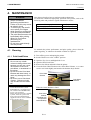
MAINTENANCE .................................................................................................................... E4- 1
4.1
5.
Cleaning ....................................................................................................................... E4- 1
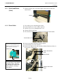
4.1.1 Print Head/Platen ......................................................................................................E4- 1
4.1.2 Pinch Roller ...............................................................................................................E4- 2
4.1.3 Under the Media Guides............................................................................................E4- 5
4.1.4 Covers and Panels ....................................................................................................E4- 6
4.1.5 Optional Cutter Module..............................................................................................E4- 7
4.1.6 Optional Strip Module ................................................................................................E4- 9
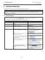
TROUBLESHOOTING .......................................................................................................... E5- 1
5.1
5.2
5.3
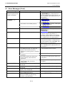
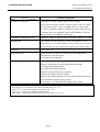
Error Messages ............................................................................................................ E5- 1
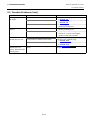
Possible Problems ........................................................................................................ E5- 3
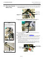
Removing Jammed Media............................................................................................ E5- 5
6.
PRINTER SPECIFICATIONS ................................................................................................ E6- 1
7.
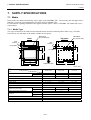
SUPPLY SPECIFICATIONS ................................................................................................. E7- 1
7.1
7.2
7.3
7.4
Media............................................................................................................................ E7- 1
7.1.1 Media Type......................................................................................................... E7- 1
7.1.2 Detection Area of the Transmissive Sensor ....................................................... E7- 2
7.1.3 Detection Area of the Reflective Sensor............................................................. E7- 3
7.1.4 Effective Print Area............................................................................................. E7- 3
Ribbon .......................................................................................................................... E7- 4
Recommended Media and Ribbon Types .................................................................... E7- 4
Care/Handling of Media and Ribbon ............................................................................ E7- 5
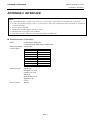
APPENDIX 1 MESSAGES AND LEDS......................................................................................EA1-1
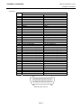
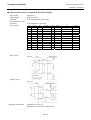
APPENDIX 2 INTERFACE .........................................................................................................EA2-1
APPENDIX 3 POWER CORD ....................................................................................................EA3-1
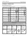
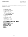
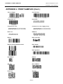
APPENDIX 4 PRINT SAMPLES ................................................................................................EA4-1
APPENDIX 5 GLOSSARIES ......................................................................................................EA5-1
INDEX
WARNING!
This is a Class A product. In a domestic environment this product may cause radio interference in
which case the user may be required to take adequate measures.
CAUTION!
1. This manual may not be copied in whole or in part without prior written permission of TOSHIBA
TEC.
2. The contents of this manual may be changed without notification.
3. Please refer to your local Authorised Service representative with regard to any queries you may
have in this manual.
1. PRODUCT OVERVIEW
ENGLISH VERSION EO1-33057
1.1 Introduction
1. PRODUCT OVERVIEW
1.1 Introduction
Thank you for choosing the TOSHIBA B-SX8T series thermal printer.
This Owner’s Manual contains from general set-up through how to
confirm the printer operation using an online test print, and should be
read carefully to help gain maximum performance and life from your
printer. For most queries please refer to this manual and keep it safe for
future reference. Please contact your TOSHIBA TEC representative for
further information concerning this manual.
1.2 Features
This printer has the following features:
• Various kinds of interface
Various kinds of interface are provided:
<Standard>
<Option>
• Parallel
• Serial
• USB
• Wireless LAN
• LAN
• RFID
• Expansion I/O
• Superior hardware
Clear print quality is realised by an 12 dots/mm (305 dpi) print head, at
a printing speed of 76.2 mm/sec. (3 inches/sec.), 101.6 mm/sec. (4
inches/sec.), or 203.2 mm/sec. (8 inches/sec.)
• Heavy-duty enclosure
As the enclosure is made of metal, the printer can be used in an
industrial environment such as a factory.
• A variety of options
The following optional devices are available:
• Cutter module
• Strip module
• Serial interface board
• Wireless LAN board
• RFID module (Future option)
• Metal Supply Cover (Future option)
• Expansion I/O board
• Real Time Clock
E1- 1
1. PRODUCT OVERVIEW
ENGLISH VERSION EO1-33057
1.3 Accessories
1.3
Accessories
NOTE:
As a power cord is not supplied
with this printer, please purchase
one that meets each country’s
safety standard. For details, refer
to APPENDIX 3.
When unpacking the printer, please make sure all the following
accessories are supplied with the printer.
Start-up CD-ROM (1 pc.)
<Contents>
•
•
•
•
•
Bar code print application (Bartender ultra lite)
Windows Driver
Owner’s Manual
Specifications (Programming, Key operation, etc.)
Product information (Catalogue)
Supply Loading Instructions
(Doc. No.: EO2-33023)
Safety Precautions
(Doc. No.: EO2-33024)
Quality Control Report
(1 sheet)
Warranty Disclaimer Sheet
(1 sheet)
Print Head Cleaner (1 pc.)
Media Holder (2 pcs.)
Supply Holder Frame (L)
(1 pc.)
Supply Holder Frame (R)
(1 pc.)
Supply Shaft (1 pc.)
Supply Holder Base (1 pc.)
Wing Bolt (2 pcs.)
E1- 2
1. PRODUCT OVERVIEW
ENGLISH VERSION EO1-33057
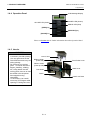
1.4 Appearance
1.4 Appearance
The names of the parts or units introduced in this section are used in the
following chapters.
417 (16.4 )
282 (16.4 )
395 (15.6)
1.4.1 Dimensions
Dimensions in mm (inches)
1.4.2 Front View
Top Cover
LCD Message
Display
Operation Panel
Right Side Cover
Head Lever
Media Outlet
Power Switch
0: OFF
1: ON
1.4.3 Rear View
Parallel Interface Connector
(Centronics)
Media Guide
Media Holder
Ass’y
AC Power Inlet
E1- 3
RS-232C Serial
Interface Connector
(Option)
Wireless LAN Interface
Board (Option)
Expansion I/O Interface
Connector (Option)
USB Interface
Connector
LAN Interface
Connector
1. PRODUCT OVERVIEW
ENGLISH VERSION EO1-33057
1.4 Appearance
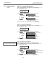
1.4.4 Operation Panel
LCD Message Display
POWER LED (Green)
ON LINE LED (Green)
ERROR LED (Red)
[FEED] key
[RESTART] key
[PAUSE] key
Please see Section 3.1 for further information about the Operation Panel.
1.4.5 Interior
WARNING!
1. Do not touch the Print Head
or around it just after printing.
You may get burned as the
Print Head becomes very hot
during printing.
2. Do not touch any moving
parts. To reduce the risk of
fingers, jewellery, clothing,
etc., being drawn into the
moving parts, be sure to load
the media once the printer
has stopped moving
completely.
3. To avoid injury, be careful
not to trap your fingers while
opening or closing the cover.
Caution Label
Ribbon Holder
(Feed side)
Pinch Roller Lever
Ribbon Holder
(Take-up side)
Print Head
Head Lever
Platen
Head Lock Plate
E1- 4
1. PRODUCT OVERVIEW
ENGLISH VERSION EO1-33057
1.5 Options
1.5
Options
Option Name
Cutter module
Type
B-SX208-QM-R
Strip module
B-SX908-H-QM-R
Serial Interface
Board
Wireless LAN
Board
Expansion I/O
Board
Real Time Clock
B-SA704-RS-QM-R
RFID module
(Future Option)
B-SX708-RFID-U1-US-R
B-SX708-RFID-U1-EU-R
B-SX708-RFID-H1-QM-R
B-SX908-MC-QM-R
This option is intended to protect a media roll from dirt or dust.
Metal Supply
Cover
(Future Option)
B-SA704-WLAN-QM-R
B-SA704-IO-QM-R
B-SA704-RTC-QM-R
Usage
A cutter which cuts the media one by one. This module is slim
and compact enough to be fitted in the Front Cover.
This module peels off a printed label from the backing paper at
the media outlet. It is slim and compact enough to be fitted in
the Front Cover.
Installing this PC board provides an RS232C interface port.
Installing this PC board allows a communication by wireless
LAN.
Installing this board in the printer allows a connection with an
external device with the exclusive interface.
This module holds the current time: year, month, day, hour,
minute, second
Installing this module enables read and write of RFID tags.
NOTE:
To purchase the optional kits, please contact the nearest authorised TOSHIBA TEC representative or TOSHIBA
TEC Head Quarters.
E1- 5
2. PRINTER SETUP
ENGLISH VERSION EO1-33057
2. PRINTER SETUP
2. PRINTER SETUP
This section outlines the procedures to setup your printer prior to its operation. The section includes precautions,
loading media and ribbon, connecting cables, setting the operating environment of the printer, and performing an
online print test.
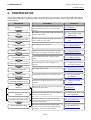
Setup Flow
Installation
Assembling the supply holder
frame
Procedure
After referring to the Safety Precautions in this
manual, install the printer on a safe and stable
location.
Reference
2.1 Installation
Assemble the supply holder stand, and attach it to
the rear of the printer.
2.2 Assembling the Supply
Holder Frame
Connect a power cord to the power inlet of the
printer, then, to an AC outlet.
2.3 Connecting the Power
Cord
Load a label stock or tag stock.
2.4 Loading the Media
Adjust the position of feed gap sensor or black
mark sensor according to the media to be used.
2.4 Loading the Media
Loading the ribbon
In case of thermal transfer printing, load the
ribbon.
2.5 Loading the Ribbon
Connecting to a host computer
Connect the printer to a host computer or a
network.
2.6 Connecting the Printer to
Your Host Computer
Turn on the printer power.
2.7 Turning the Power ON
Set the printer parameters in the system mode.
2.8 Setting an Operating
Environment
If necessary, install the printer driver in your host
computer.
2.9 Installing the Printer
Drivers
Print test
Make a print test in your operating environment
and check the print result.
2.10 Print Test
Position and Print Tone Fine
adjustment
If necessary, fine adjust the print start position,
cut/strip position, print tone, etc.
2.11 Position and Print Tone
Fine Adjustment
Automatic threshold setting
If the print start position cannot be detected
properly when pre-printed label is used, set the
threshold automatically.
Manual threshold setting
If the print start position cannot be detected
properly even an automatic threshold setting is
performing, manually set the threshold.
Connecting the power cord
Loading the media
Media sensor position
alignment
Turning the power ON
Setting the operating
environment
Installing the printer driver
E2- 1
2.12 Threshold Setting
2.12 Threshold Setting
2. PRINTER SETUP
ENGLISH VERSION EO1-33057
2.1 Installation
2.1 Installation
To insure the best operating environment, and to assure the safety of the
operator and the equipment, please observe the following precautions.
• Operate the printer on a stable, level, operating surface in a location
free from excessive humidity, high temperature, dust, vibration or
direct sunlight.
• Keep your work environment static free. Static discharge can cause
damage to delicate internal components.
• Make sure that the printer is connected to a clean source of AC
Power and that no other high voltage devices that may cause line
noise interference are connected to the same mains.
• Assure that the printer is connected to the AC mains with a threeprong power cable that has the proper ground (earth) connection.
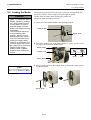
2.2. Assembling the
Supply Holder Frame
1. Assemble the Supply Holder Frame (L) and Supply Holder Frame (R)
to the Supply Holder Base using the two M-4X6 Wing Bolts supplied,
as shown below.
.
Supply Holder Frame (L)
Wing Bolt
Supply Holder Base
Dowel
(M-4x6)
Supply Holder Frame (R)
2. Attach the assembled Supply Holder Frame to the rear of the printer
by inserting the hooks of the Frame into the two slots in the rear of the
printer, as shown below.
Slot
Hook
Supply Holder Frame
E2- 2
Printer
2. PRINTER SETUP
ENGLISH VERSION EO1-33057
2.3 Connecting the Power Cord
2.3 Connecting the
Power Cord
1. Make sure that the printer Power Switch is in the OFF ({) position.
Connect the Power Cord to the printer as shown in the figure below
CAUTION!
As a Power Cord is not supplied
with the printer, please purchase
an approved on that meets the
safety standard of each country.
(Refer to APPENDIX 3.)
Power Switch
Power Cord
2. Plug the other end of the Power Cord into a grounded outlet as shown
in the figure below.
Power Cord
[Example of US Type]
E2- 3
Power Cord
[Example of EU Type]
2. PRINTER SETUP
ENGLISH VERSION EO1-33057
2.4 Loading the Media
2.4 Loading the Media
WARNING!
1. Do not touch any moving
parts. To reduce the risk of
fingers, jewellery, clothing,
etc., being drawn into the
moving parts, be sure to
load the media once the
printer has stopped moving
completely.
2. The Print Head becomes
hot immediately after
printing. Allow it to cool
before loading the media.
3. Care must be taken not to
pinch your fingers when
opening or closing the Top
Cover or Right Side Cover.
4. Be careful not to pinch your
fingers by the Supply
Holder Frame or Media
Holders when loading the
media.
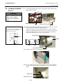
The following procedure shows the steps to properly load the media into
the printer so that it feeds straight and true through the printer.
Use the same procedure when replacing the media, also.
The printer prints both labels and tags.
1. Install one of the Media Holders onto the Supply Shaft.
Media Holder
Supply Shaft
2. Turn the Locking Lever of the Media Holder to “Close” position to fix
the Supply Shaft with the Media Holder.
Media Holder
Locking Lever
Close
Open
Supply Shaft
NOTE:
For the specification of available
media, refer to Section 7.1 Media.
3. Place a media roll onto the Supply Shaft and push the media against
the Media Holder.
Supply Shaft
E2- 4
Media
2. PRINTER SETUP
ENGLISH VERSION EO1-33057
2.4 Loading the Media
2.4 Loading the Media
(Cont.)
4. Install the other Media Holder onto the Supply Shaft from the
opposite side.
Media Holder
Supply Shaft
5. Turn the Locking Lever of the Media Holder to the “Close” position.
Media Holder
“Close” Position
Locking Lever
Media
6. Set the Head Lever to the “OPEN” position.
“OPEN”
position
Head Lever
7. Open the Top Cover and the Right Side Cover.
Top Cover
Right Side Cover
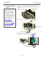
8. Open the Head Lock Plate (c), and turn the Pinch Roller Lever
clockwise (d) to release the Pinch Roller.
d
Pinch Roller Lever
c
Head Lock Plate
E2- 5
2. PRINTER SETUP
ENGLISH VERSION EO1-33057
2.4 Loading the Media
2.4 Loading the Media
(Cont.)
9.
Loosen the Media Guide Screws on the printer back, and move the
Media Guides outside.
Media Guide
WARNING!
Be careful not to pinch your
fingers or hands by the Supply
Holder Frame or Media
Holders when loading the
media.
Media Guide Screw
NOTE:
Place the bushes of the Supply Shaft
into the notches of the Supply
Holder Frame securely.
Supply Holder Frame
10. Place the assembled Media Holder onto the Supply Holder Frame, and
feed the media between the two Media Guides.
Turn the Locking Lever of the Media Holder to the “Open” position,
and push the Media Holders toward the centre to place the media at the
centre on the Supply Shaft. Then, lock the position of the media by
returning the Locking Levers to the “Close” position.
Media Holder
Bush
Media
Notch
Close
Open
Media Holder Frame
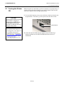
11. Feed the media until it extends past the Platen.
12. Move the Media Guides inside, causing the media to be automatically
centred. Then, tighten the Media Guide Screws to secure the Media
Guides.
Media Guide
Media Guide Screw
E2- 6
2. PRINTER SETUP
ENGLISH VERSION EO1-33057
2.4 Loading the Media
2.4 Loading the Media
(Cont.)
NOTES:
1. When using the Movable sensor,
choose the Movable sensor for
the parameter setting in the
system mode (Section 2.8.1
Parameter Setting). The Fixed
sensor has been selected as
default.
2. The position of the movable
sensor should be adjusted
before loading the ribbon.
Otherwise, the sensor is
covered by the ribbon, causing
the sensor position adjustment
to be disabled.
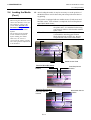
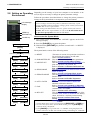
13. After loading the media, it may be necessary to set the position of
the Media Sensor used to detect the print start position for label or
tag printing.
This printer is equipped with two media sensors: Fixed sensor and
Movable sensor. Each of them is comprised of a Feed Gap Sensor
and a Black Mark Sensor.
Fixed sensor:
Movable sensor:
This sensor is positioned at the centre of
the printer unit. It is intended for detecting
gaps between labels or black marks marked
at the centre.
The position of this sensor is adjustable. It
is intended for detecting gaps between
labels, black marks, notches, etc. that are
not positioned at the centre of the media.
Movable Sensor
Fixed Sensor
Media Sensor Plate
Detail of Movable Sensor
Black Mark Sensor
Position
Feed Gap Sensor
Position
Detail of Fixed Sensor
Feed Gap Sensor
Position
E2- 7
Black Mark Sensor
Position
2. PRINTER SETUP
ENGLISH VERSION EO1-33057
2.4 Loading the Media
2.4 Loading the Media
(Cont.)
NOTE:
Adjustment Knob
Forward: Moves toward the centre
of the printer.
Backward: Moves away from the
centre of the printer.
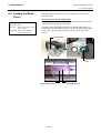
The following procedures show how to adjust the position of the
movable sensor.
Feed Gap Sensor position adjustment
When using a label stock without black marks, the Feed Gap Sensor
is used to detect the print start position.
Looking inside of the Media Outlet, move the Movable Sensor by
rotating the Adjustment Knob until the Feed Gap Sensor aligns with
a gap. (The right side hole indicates the position of the Feed Gap
Sensor.)
Media Outlet
Adjustment
Knob
Backward
Left side hole:
Black Mark Sensor
E2- 8
Forward
Right side hole:
Feed Gap Sensor
2. PRINTER SETUP
ENGLISH VERSION EO1-33057
2.4 Loading the Media
2.4 Loading the Media
(Cont.)
NOTE:
Be sure to set the Black Mark
Sensor to detect the centre of the
black mark, otherwise a paper jam
or no paper error may occur.
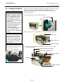
Black Mark Sensor position adjustment
When using media with black marks, the Black Mark Sensor is used
to detect the print start position.
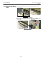
(1) Pull the media about 500 mm out of the front of the printer, turn the
media back on it’s self and feed it under the print head.
Black Mark
Media
(2) Move the Movable Sensor by rotating the Adjustment Knob, until the
Black Mark Sensor aligns with a black mark. (The left side hole
indicates the position of the Black Mark Sensor).
Left side hole:
Black Mark Sensor
Right side hole:
Feed Gap Sensor
Forward
Backward
Media
Adjustment
Knob
E2- 9
2. PRINTER SETUP
ENGLISH VERSION EO1-33057
2.4 Loading the Media
2.4 Loading the Media
(Cont.)
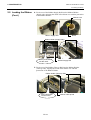
14. There are three issue modes available on this printer. How to set the
media for each mode is provided below.
Batch mode
In the batch mode, the media is continuously printed and fed until the
number of labels/tags specified in the issue command have been printed.
(1) Pull the media past the media outlet.
Media Outlet
(2) Turn the Pinch Roller Lever counterclockwise to lock the Pinch
Roller.
Pinch Roller Lever
(3) Close the Top Cover and Right Side Cover.
Top Cover
Right Side Cover
E2-10
2. PRINTER SETUP
ENGLISH VERSION EO1-33057
2.4 Loading the Media
2.4 Loading the Media
(Cont.)
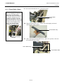
Strip mode (Option)
When the optional Strip Module is fitted, a label is automatically
removed from the backing paper at the Strip Plate as each label is printed.
(1) Pull out the backing paper past the Media Outlet.
Backing Paper
Strip module
Media Outlet
WARNING!
When the Backing Paper
Release Bar is released, it is
automatically closed by the
spring. Care must be taken
not to pinch your fingers or
hands.
(2) While holding down the Backing Paper Release Bar, and pass the
backing paper between the Backing Paper Holder and the Strip Roller.
Then, release the Backing Paper Release Bar.
Backing Paper
Strip Roller
Backing Paper Release Bar
Backing Paper Holder
(3) Turn the Pinch Roller Lever counterclockwise to lock the Pinch
Roller.
Pinch Roller Lever
(4) Close the Top Cover and Right Side Cover.
Top Cover
Right Side Cover
E2-11
2. PRINTER SETUP
ENGLISH VERSION EO1-33057
2.4 Loading the Media
2.4 Loading the Media
(Cont.)
WARNING!
The cutter is sharp, so care
must be taken not to injure
your fingers when handling the
cutter.
CAUTION!
1. When using a label stock, be
sure to cut the gaps. Cutting
labels will cause the glue to
stick to the cutter, which may
affect the cutter quality and
shorten the cutter life.
2. Use of tag paper which
thickness exceeds specified
value may affect the cutter
life. For the specification of
the media, refer to Section
7.1 Media.
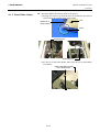
Cut mode (Option)
When the optional Cutter Module is fitted, the media is automatically cut.
(1) Insert the leading edge of the media into the Media Outlet of the
Cutter Module.
Cutter module
(2) Turn the Pinch Roller Lever counterclockwise to lock the Pinch
Roller.
Pinch Roller Lever
(3) Close the Top Cover and Right Side Cover.
Top Cover
Right Side Cover
E2-12
2. PRINTER SETUP
ENGLISH VERSION EO1-33057
2.4 Loading the Media
2.4 Loading the Media
(Cont.)
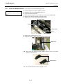
15. Change the print head pressure according to the thickness of the
media to be used, by using the Head Lever.
Head Lever
Position
Media type or thickness
Label or Thin media
1
If a clear print cannot be obtained,
change the position to d.
Tag paper or Thick paper
2
If a clear print cannot be obtained,
change the position to c.
16. If the loaded media is direct thermal media (with a chemically
treated surface), the media loading procedure is now completed.
If the media is normal media, it is also necessary to load a ribbon.
Refer to Section 2.5 Loading the Ribbon.
E2-13
2. PRINTER SETUP
ENGLISH VERSION EO1-33057
2.5 Loading the Ribbon
2.5 Loading the Ribbon
WARNING!
1. Do not touch any moving
parts. To reduce the risk of
fingers, jewellery, clothing,
etc., being drawn into the
moving parts, be sure to
load the ribbon once the
printer has stopped moving
completely.
2. The print head becomes hot
immediately after printing.
Allow it to cool before
loading the ribbon.
3. To avoid injury, be careful
not to trap your fingers
while opening or closing the
cover.
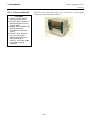
There are two types of media available for printing on: these are thermal
transfer media (normal media) and direct thermal media (with a
chemically treated surface). DO NOT LOAD a ribbon when using a
direct thermal media.
1. Set the Head Lever to the “OPEN” position.
“Open” Position
Head Lever
2. Open the Top Cover, Right Side Cover, and the Head Lock Plate.
CAUTION!
Be careful not touch the Print
Head Element when opening
the Top Cover. Failure to do
this may cause missing dots by
static electricity or other print
quality problems.
NOTE:
Do not change the Ribbon Holder
Adjustment Lever positions. Doing
so will change the adjustment.
Top Cover
Right Side Cover
Head Lock Plate
3. Leaving plenty of slack between the ribbon spools, insert the ribbon
under the Print Block.
Ribbon Holder (Take-up Side)
Ribbon Holder Adjustment Lever
Ribbon Holder (Supply Side)
Ribbon Supply
Roll
Print Block
Ribbon Take-up
Roll
E2-14
2. PRINTER SETUP
ENGLISH VERSION EO1-33057
2.5 Loading the Ribbon
2.5 Loading the Ribbon
(Cont.)
4. Fit the core of the Ribbon Supply Roll into the Ribbon Holders
(Supply side), aligning the notch of the ribbon core with the protrusion
of the Ribbon Holder.
Ribbon Core
Notch
Ribbon Supply Roll
Ribbon Holder (Supply Side)
Fit the protrusion
into the notch.
Ribbon Supply Roll
5. Fit the core of the Ribbon Take-up Roll into the Ribbon Holders
(Take-up side), aligning the notch of the ribbon core with the
protrusion of the Ribbon Holder.
Ribbon Holder (Take-up Side)
Fit the protrusion
into the notch.
E2-15
Ribbon Take-up Roll
2. PRINTER SETUP
ENGLISH VERSION EO1-33057
2.5 Loading the Ribbon
2.5 Loading the Ribbon
(Cont.)
1.
2.
3.
4.
5.
NOTES:
Be sure to remove any slack in
the ribbon when printing.
Printing with a wrinkled ribbon
will lower the print quality.
When a ribbon end is detected,
“RIBBON ERROR” message
will appear on the display and
the ERROR LED will illuminate.
When disposing of the ribbons,
please follow the local rules.
For the specification of
available ribbon, refer to
Section 7.2 Ribbon.
When using a non transparent
ribbon, choose the Non trans
ribbon for the parameter setting
in the system mode. (Section
2.8.1 Parameter Setting.)
Transparent ribbon has been
selected as default.
6. Take up any slack in the ribbon. Wind the leading tape onto the
ribbon take-up roll until the ink ribbon can be seen from the front of
the printer.
Ribbon Supply Roll
Ribbon Take-up Roll
7. Close the Head Lock Plate, Right Side Cover, and Top Cover.
Top Cover
Right Side Cover
Head Lock Plate
8. Turn the Head Lever to the Position 1 or 2. For the difference
between Position 1 and Position 2, refer to Section 2.4.
Head Lever
2: Tag paper or Thick paper
1: Label or Thin media
E2-16
2. PRINTER SETUP
ENGLISH VERSION EO1-33057
2.6 Connecting the Printer to Your Host Computer
2.6 Connecting the
Printer to Your Host
Computer
CAUTION!
Do not directly connect the LAN
cable which is wired outside of a
building to the LAN port
provided on this product, as the
LAN port on this product is
intended for indoor connection.
To connect such LAN cable to
the product, be sure to use any
communication equipment, like
a router, a hub, or a modem
which is located within the same
building as the product.
The following paragraphs outline how to connect your host computer to
the printer, and will also show how to make cable connections to other
devices. Depending on the system configuration you use to print labels,
there are 5 possibilities for connecting the printer to your host computer.
These are:
• A parallel cable connection between the printer’s standard parallel
connector and your host computer’s parallel port (LPT).
• An Ethernet connection using the standard LAN board.
• A USB cable connection between the printer’s standard USB
connector and your host computer’s USB port. (Conforming to
USB 2.0 Full Speed)
• A serial cable connection between the printer’s optional RS-232C
serial connector and one of your host computer’s COM ports.
<Option>
• Wireless LAN using an optional Wireless LAN board. <Option>
For details of each interface, refer to APPENDIX 2.
After connecting the necessary interface cables, set an operating
environment of the printer. Refer to Section 2.8.1 Parameter Setting.
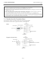
The diagram below shows all the possible cable connections to the
current version of the printer.
Standard Interface
and
Optional Interface
Power Inlet
Standard
Parallel Interface Connector
(Centronics)
USB Interface Connector
LAN Interface Connector
Expansion I/O Board (Option),
Serial Interface (RS-232C)
(Option)
Wireless LAN (Option)
Expansion
I/O
Serial
Interface
E2-17
Wireless LAN
2. PRINTER SETUP
ENGLISH VERSION EO1-33057
2.7 Turning the Printer ON
2.7 Turning the Printer
ON
CAUTION!
When the printer is connected to your host computer it is good practice to
turn the printer ON before turning on your host computer and turn OFF
your host computer before turning off the printer.
1. To turn ON the printer power, press the Power Switch as shown in the
diagram below. Note that ( | ) is the power ON side of the switch.
Use the power switch to turn the
printer On/Off. Plugging or
unplugging the Power Cord to
turn the printer On/Off may
cause fire, an electric shock, or
damage to the printer.
NOTES:
1. If a message other than ON
LINE appears on the display or
the ERROR LED (Red) is
illuminated, go to Section 5.1,
Error Messages.
2. To turn OFF the printer power
turn the Power Switch to the
“{” side position.
Power Switch
2. Check that the ON LINE message appears in the LCD Message
Display and that the ON LINE and POWER LED (Green) are
illuminated.
E2-18
2. PRINTER SETUP
ENGLISH VERSION EO1-33057
2.8 Setting an Operating Environment
2.8 Setting an Operating
Environment
Depending on the settings of your host computer or an interface to be
used, it may be necessary to change the printer parameter settings.
Follow the procedures described below to change the printer parameter
settings in the System Mode to correspond to your environment.
LCD Message
Display
FEED key
NOTE:
Incorrect settings can cause the printer to function erroneously. If you
have any problems with the parameter settings, please contact your nearest
TOSHIBA TEC service representative.
For the settings this manual does not cover, please contact your nearest
TOSHIBA TEC service representative, or refer to the B-SX6T/SX8T Series
Key Operation Specification stored in the CD-ROM.
RESTART key
PAUSE key
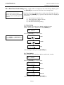
How to enter the System Mode
1. Turn on the printer and confirm that “ONLINE” appears on the LCD
Message Display.
2. Press the [PAUSE] key to pause the printer.
ON LINE
[PAUSE]
PAUSE
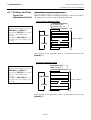
The System Mode consists of the following menus.
Hold down [RESTART] for 3 sec.
<1>RESET
[FEED]
[RESTART]
<2>PARAMETER SET
[FEED]
[RESTART]
<3>ADJUST SET
[FEED]
[RESTART]
<4>DUMP MODE
[FEED]
[RESTART]
<5>EXPAND MODE
[FEED]
[RESTART]
<6>AUTO CALIB
[FEED]
[RESTART]
<7>LAN
[FEED]
[RESTART]
<8>RTC SET
[FEED]
3. Hold down the [RESTART] key for three seconds until “<1>RESET”
is displayed.
[RESTART]
<1>RESET
This menu is used to clear print data sent from a
PC and return the printer to an idle state.
Refer to Section 3.3 Reset.
<2>PARAMETER SET This menu is used to set the printer parameters.
Refer to Section 2.8.1 Parameter Setting.
<3>ADJUST SET
This menu is used to make a fine adjustment of a
print start position, cut position, etc.
Refer to Section 2.11 Position and Print Tone
Fine Adjustment.
<4>DUMP MODE
This menu is used to print the data in the receive
buffer for debug.
Refer to Section 2.8.2 Dump Mode Setting.
<5>EXPAND MODE
This menu is used to start the program for
BASIC mode.
Refer to Section 2.8.3 BASIC Expansion
Mode.
<6>AUTO CALIB
This menu is used to enable or disable the
automatic calibration function.
Refer to Section 2.8.4 Automatic Calibration.
<7>LAN
This menu is used to enable or disable the LAN
communication and SNMP.
Refer to Section 2.8.5 LAN Setting.
<8>RTC SET
This menu is used to set the date and time of the
real time clock, enable or disable the low battery
check, and choose a real time renewal timing.
Refer to Section 2.8.6 Real Time Clock
Setting.
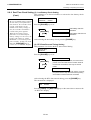
NOTES:
1. System Mode menus can be selected with the [RESTART] or [FEED] key.
2. To enter each of the above System Mode menus, press the [PAUSE] key
when the menu is displayed.
3. If the [PAUSE] key is pressed with “<1>RESET” being displayed, the
printer will turn to an idle state and the message will change to “ONLINE”
E2-19
2. PRINTER SETUP
ENGLISH VERSION EO1-33057
2.8 Setting an Operating Environment
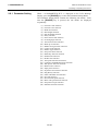
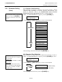
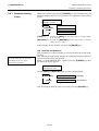
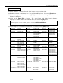
2.8.1 Parameter Setting
While “<2>PARAMETER SET” is displayed on the LCD Message
Display, press the [PAUSE] key to enter the Parameter Setting Mode.
The Parameter Setting Mode contains the following sub menus. Each
time the [PAUSE] key is pressed, the sub menus are displayed
sequentially.
(1)
(2)
(3)
(4)
(5)
(6)
(7)
(8)
(9)
(10)
(11)
(12)
(13)
(14)
(15)
(16)
(17)
(18)
(19)
(20)
(21)
(22)
(23)
(24)
(25)
(26)
(27)
(28)
(29)
(30)
Character code selection
Character zero selection
Baud rate selection
Data length selection
Stop bit length selection
Parity selection
Flow control code selection
LCD language selection
Auto forward wait selection
Head up cut selection
Ribbon saving function selection
Control code selection
Ribbon Type Selection
Strip wait status selection
FEED key function selection
KANJI code selection
EURO code selection
Auto print head check selection
Centronics ACK/BUSY timing selection
Web printer function selection
Media sensor selection
Input prime selection
Expansion I/O interface selection
Plug & Play selection
Label end/ribbon end selection
Pre-strip selection
Reverse feed speed selection
Maxi code specification selection
Strip motor torque selection
Stabilizer function selection
E2-20
2. PRINTER SETUP
ENGLISH VERSION EO1-33057
2.8 Setting an Operating Environment
2.8.1 Parameter Setting
(Cont.)
NOTE:
Be careful if the printer is turned off
without pressing the [PAUSE] key,
the selected value does not become
effective.
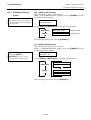
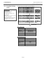
(1) Character Code Selection
This parameter is to choose a character code used for printing. Printed
characters differ depending on a chosen character code and font. For
details of characters, refer to the B-SX6T/SX8T Series External
Equipment Interface Specification (Printer Command Manual).
When “<2>PARAMETER SET” appears, press the [PAUSE] key.
<2>PARAMETER SET
FONT CODE PC-850
Use the [FEED] or [RESTART] key to select a desired option.
FONT CODE PC-850
FONT CODE PC-852
FONT CODE PC-857
[RESTART]
FONT CODE PC-8
FONT CODE PC-851
FONT CODE PC-855
FONT CODE PC1250
FONT CODE PC1251
FONT CODE PC1252
FONT CODE PC1253
FONT CODE PC1254
FONT CODE PC1257
[FEED]
FONT CODE LATIN9
FONT CODE Arabic
FONT CODE PC-866
FONT CODE UTF-8
After selecting a character code, press the [PAUSE] key.
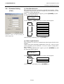
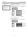
(2) Character Zero Selection
NOTE:
The following fonts do not support a
zero with slash.
Bit Map Font:
OCR-A, OCR-B, GOTHIC 725 Black,
Kanji, Chinese
Outline Font:
Price Font 1, Price Font 2, Price
Font 3, DUTCH 801 Bold, BRUSH
738 Regular, GOTHIC 725 Black,
True Type Font
This parameter is to choose the way to indicate zero between “0” and “Ø”.
When “<2>PARAMETER SET” appears, press the [PAUSE] key twice.
<2>PARAMETER SET
ZERO FONT
0
Use the [FEED] or [RESTART] key to select a desired option.
[RESTART]
[FEED]
ZERO FONT
0
ZERO FONT
Ø
(Without slash)
(With slash)
After selecting a character zero, press the [PAUSE] key.
E2-21
2. PRINTER SETUP
ENGLISH VERSION EO1-33057
2.8 Setting an Operating Environment
2.8.1 Parameter Setting
(Cont.)
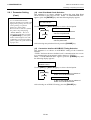
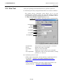
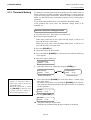
(3) Baud Rate Selection
This parameter is to choose a baud rate of the RS-232C interface. When
the printer communicates with a host computer by serial interface, be sure
to match the setting with the host.
When “<2>PARAMETER SET” appears, press the [PAUSE] key until
the following display appears.
<2>PARAMETER SET
SPEED 9600bps
Use the [FEED] or [RESTART] key to select a desired option.
SPEED 115200 bps
[RESTART]
SPEED 38400 bps
SPEED 19200 bps
SPEED 9600 bps
[FEED]
<Reference>
Properties screen of Serial (COM) port
under Windows98
SPEED 4800 bps
SPEED 2400 bps
After selecting a baud rate, press the [PAUSE] key.
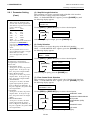
(4) Data Length Selection
This parameter is to choose a communication data length of the RS-232C
interface.
7 bits is used when transmitting alphanumeric data only. 8 bits is used to
when transmitting special characters. Be sure to match a setting with a
host computer.
When “<2>PARAMETER SET” appears, press the [PAUSE] key until
the following display appears.
<2>PARAMETER SET
DATA LENG. 8bits
Use the [FEED] or [RESTART] key to select a desired option.
[RESTART]
DATA LENG. 8bits
[FEED]
DATA LENG. 7bits
After selecting a data length, press the [PAUSE] key.
E2-22
2. PRINTER SETUP
ENGLISH VERSION EO1-33057
2.8 Setting an Operating Environment
2.8.1 Parameter Setting
(Cont.)
NOTES:
1. When using the hardware flow
control, the control signals and
data must be in pairs between the
printer and the PC.
Printer
Host
TD
→
RD
RD
←
TD
RTS
→
CTS
CTS
←
RTS
DSR
→
DTR
DTR
←
DSR
Refer to the RS-232C connector’s
pin layout in APPENDIX 2.
Check if the printer and the PC is
properly connectable with your
cable
2. Be careful that there are two
types of RS-232C cable; straight
cable and cross cable.
Use a straight cable for this
printer.
NOTE:
The following is the detailed
descriptions for each transmission
control code.
1) XON/XOFF AUTO
At the power on time, the printer
outputs XON. At the power off
time, the printer outputs XOFF.
2) XON+READY AUTO
At the power on time, the printer
outputs XON. At the power off
time, the printer outputs XOFF.
3) READY/BUSY
At the power on time, the DTR
signal output from the printer
turns to High level (READY). At
the power off time, the printer does
not output XOFF.
4) ON/XOFF
At the power on time, the printer
outputs XON. At the power off
time, the printer does not output
XOFF.
5) READY/BUSY RTS
At the power on time, the RTS
signal output from the printer
turns to High level (READY). At
the power off time, the printer does
not output XOFF.
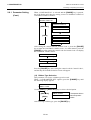
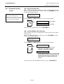
(5) Stop Bit Length Selection
This parameter is to choose a stop bit length of the RS-232C interface.
Be sure to match a setting with a host computer.
When “<2>PARAMETER SET” appears, press the [PAUSE] key until
the following display appears.
<2>PARAMETER SET
STOP BIT 1bit
Use the [FEED] or [RESTART] key to select a desired option.
[RESTART]
[FEED]
STOP BIT 1bit
STOP BIT 2bits
After selecting a stop bit length, press the [PAUSE] key.
(6) Parity Selection
This parameter is to choose the parity of the RS-232C interface.
When “<2>PARAMETER SET” appears, press the [PAUSE] key until
the following display appears.
<2>PARAMETER SET
PARITY NONE
Use the [FEED] or [RESTART] key to select a desired option.
PARITY
EVEN
PARITY
ODD
PARITY
NONE
[RESTART]
[FEED]
After selecting the parity, press the [PAUSE] key.
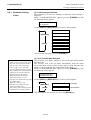
(7) Flow Control Code Selection
This parameter is to choose a flow control code of the RS-232C interface.
When “<2>PARAMETER SET” appears, press the [PAUSE] key until
the following display appears.
<2>PARAMETER SET
XON+READY AUTO
Use the [FEED] or [RESTART] key to select a desired option.
XON/XOFF AUTO
[RESTART]
XON+READY AUTO
READY/BUSY
[FEED]
XON/XOFF mode
XON/XOFF+READY/BUSY
(DTR) mode
READY/BUSY (DTR)
mode
XON/XOFF
XON/XOFF mode
READY/BUSY RTS
RTS mode
After selecting a flow control code, press the [PAUSE] key.
E2-23
2. PRINTER SETUP
ENGLISH VERSION EO1-33057
2.8 Setting an Operating Environment
2.8.1 Parameter Setting
(Cont.)
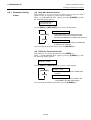
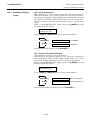
(8) LCD Language Selection
This parameter is to choose a language in which the LCD message is
displayed.
When “<2>PARAMETER SET” appears, press the [PAUSE] key until
the following display appears.
<2>PARAMETER SET
LCD ENGLISH
Use the [FEED] or [RESTART] key to select a desired option.
ENGLISH
[RESTART]
ITALIAN
JAPANESE
SPANISH
[FEED]
DUTCH
FRENCH
GERMAN
After selecting a language, press the [PAUSE] key.
NOTES:
1. If the printer is not used for a few
days, the top edge of the media
may become curly, which may
cause a paper jam. The Auto
Forward Wait Function prevents
this problem since the media feed
amount is increased so that the
media stops past the platen.
2. When the Stop Position Fine
Adjustment Value is set in +
direction, the media will stop past
the media outlet.
When the value is set in –
direction, the media will stop
inside the media outlet.
3. This setting will be useful to fine
adjust the cut position of labels.
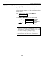
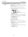
(9) Auto Forward Wait Selection
This parameter is to choose whether to activate the Auto Forward Wait
function or not.
This function, used in the cut mode, automatically feeds the media
forward for about 18 mm if there is more than 1-second idle time after
printing, to prevent the top edge of the media from curling.
When “<2>PARAMETER SET” appears, press the [PAUSE] key until
the following display appears.
<2>PARAMETER SET
FORWARD WAIT OFF
Use the [FEED] or [RESTART] key to select a desired option.
[RESTART]
FORWARD WAIT ON
Activated
[FEED]
FORWARD WAIT OFF
Not activated
After selecting an auto forward wait, press the [PAUSE] key.
E2-24
2. PRINTER SETUP
ENGLISH VERSION EO1-33057
2.8 Setting an Operating Environment
2.8.1 Parameter Setting
(Cont.)
When ON is selected, pressing the [PAUSE] key will result that the LCD
Message Display shows the stop position fine adjustment value setting
screen.
<2>PARAMETER SET
POSITION +0.0mm
POSITION +5.0mm
[RESTART]
POSITION +0.0mm
[FEED]
POSITION -5.0mm
[FEED] key:
Pressing the [FEED] key one time causes a –0.5mm change,
up to –5.0 mm.
[RESTART] key: Pressing the [RESTART] key one time causes a +0.5mm
change, up to +5.0 mm.
After selecting an auto forward wait, press the [PAUSE] key.
NOTE:
The print head may not be raised
depending on the rise of the
solenoid’s temperature.
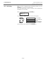
(10) Head Up Cut Selection
This parameter is to choose whether to activate the head up action in the
cut issue.
This function prevents ribbon smudges by raising the print head during a
reverse feed to the print start position.
When “<2>PARAMETER SET” appears, press the [PAUSE] key until
the following display appears.
<2>PARAMETER SET
HEAD UP CUT OFF
Use the [FEED] or [RESTART] key to select a desired option.
[RESTART]
HEAD UP CUT ON
Activated
[FEED]
HEAD UP CUT OFF
Not activated
After selecting the head up action in cut issue, press the [PAUSE] key.
E2-25
2. PRINTER SETUP
ENGLISH VERSION EO1-33057
2.8 Setting an Operating Environment
2.8.1 Parameter Setting
(Cont.)
NOTES:
1. The ribbon saving function is
activated when there is a 20-mm
or more non-print area in the
media feed direction.
2. Ribbon saving is enabled up to 4
areas per media.
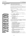
(11) Ribbon Save Function Selection
This parameter is to choose whether to activate the Ribbon Saving
function or not.
This function enables reducing the ribbon loss caused by taking up
unused ribbon during non-print areas.
When “<2>PARAMETER SET” appears, press the [PAUSE] key until
the following display appears.
<2>PARAMETER SET
RBN SAVE ON (TAG)
Use the [FEED] or [RESTART] key to select a desired option.
RBN SAVE ON (TAG)
Activated (When the head lever is set to
position 2.)
[RESTART]
RBN SAVE ON (LBL)
Activated (When the head lever is set to
position 1)
[FEED]
RBN SAVE OFF
Not activated
After selecting the ribbon save function, press the [PAUSE] key.
(12) Control Code Selection
This parameter is to choose a Control Code.
When “<2>PARAMETER SET” appears, press the [PAUSE] key until
the following display appears.
<2>PARAMETER SET
CODE AUTO
Use the [FEED] or [RESTART] key to select a desired option.
[RESTART]
[FEED]
E2-26
CODE AUTO
Automatic selection
CODE ESC,LF,NUL
Manual selection
CODE{|}
Manual selection
CODE MANUAL
Control codes should
be specified.
2. PRINTER SETUP
ENGLISH VERSION EO1-33057
2.8 Setting an Operating Environment
2.8.1 Parameter Setting
(Cont.)
When “CODE MANUAL” is selected and the [PAUSE] key is pressed,
the LCD display will show the setting screen of CONTROL CODE1 to
CONTROL CODE3 as follows.
<2>PARAMETER SET
CONTROL CODE1 1B
CONTROL CODE1 FF
[RESTART]
CONTROL CODE1 FE
CONTROL CODE1 FD
[FEED]
CONTROL CODE1 02
CONTROL CODE1 01
CONTROL CODE1 00
After setting the control code for Control Code 1, press the [PAUSE]
key to show the CONTROL CODE2 screen. In a same manner, press the
[PAUSE] key after setting the control code for Control Code 2 to display
the CONTROL CODE3 screen.
CONTROL CODE1
[PAUSE]
CONTROL CODE2
[PAUSE]
CONTROL CODE3
Press the [PAUSE] key after setting the control code for Control Code 3,
and the Strip Wait Status Selection screen will appear.
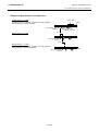
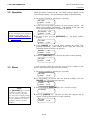
(13) Ribbon Type Selection
This parameter is to choose a ribbon type to be used.
When “<2>PARAMETER SET” appears, press the [PAUSE] key until
the following display appears.
<2>PARAMETER SET
RIBBON TRANS
Use the [FEED] or [RESTART] key to select a desired option.
[RESTART]
[FEED]
RIBBON TRANS
Transparent ribbon
RIBBON NON TRANS
Non transparent
ribbon
After selecting a ribbon type, press the [PAUSE] key.
E2-27
2. PRINTER SETUP
ENGLISH VERSION EO1-33057
2.8 Setting an Operating Environment
2.8.1 Parameter Setting
(Cont.)
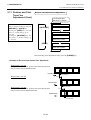
(14) Strip Wait Status Selection
This parameter is to choose when the printer sends a strip wait status
(05H) to a host in response to a status request command.
When “<2>PARAMETER SET” appears, press the [PAUSE] key until
the following display appears.
<2>PARAMETER SET
PEEL OFF STS OFF
Use the [FEED] or [RESTART] key to select a desired option.
PEEL OFF STS OFF
A strip wait status is sent when the printer
receives the next issue command and the
previously printed label is waiting to be removed.
[RESTART]
[FEED]
PEEL OFF STS ON
A strip wait status is sent when a printed label
is waiting to be removed.
After selecting the Strip Wait Status, press the [PAUSE] key.
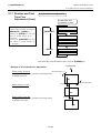
(15) FEED Key Function Selection
This parameter is to choose the function of the [FEED] key.
When “<2>PARAMETER SET” appears, press the [PAUSE] key until
the following display appears.
<2>PARAMETER SET
FEED KEY FEED
Use the [FEED] or [RESTART] key to select a desired option.
FEED KEY FEED
[RESTART]
[FEED]
The [FEED] key will feed one media when
pressed.
FEED KEY PRINT
The [FEED] key will print the data in the
Image Buffer (The last printed data)
After selecting the FEED key function, press the [PAUSE] key.
E2-28
2. PRINTER SETUP
ENGLISH VERSION EO1-33057
2.8 Setting an Operating Environment
2.8.1 Parameter Setting
(Cont.)
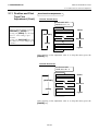
NOTE:
Kanji code selection is not supported
by the QM model as the Kanji ROMs
are not installed.
(16) KANJI Code Selection
This parameter is to choose a KANJI code.
When “<2>PARAMETER SET” appears, press the [PAUSE] key until
the following display appears.
<2>PARAMETER SET
KANJI CODE TYPE1
Use the [FEED] or [RESTART] key to select a desired option.
[RESTART]
KANJI CODE TYPE1
Windows code
[FEED]
KANJI CODE TYPE2
Original code
After selecting a Kanji code, press the [PAUSE] key.
(17) EURO Code Selection
This parameter is to choose a Euro code (€).
When “<2>PARAMETER SET” appears, press the [PAUSE] key until
the following display appears.
NOTE:
Pressing the [FEED] or
[RESTART] key causes 1 byte
change in the Euro Code value.
<2>PARAMETER SET
EURO CODE B0
Use the [FEED] or [RESTART] key to select a desired option.
[RESTART]
[FEED]
EURO CODE
20
EURO CODE
21
EURO CODE
FE
EURO CODE
FF
After selecting a Euro code, press the [PAUSE] key.
E2-29
2. PRINTER SETUP
ENGLISH VERSION EO1-33057
2.8 Setting an Operating Environment
2.8.1 Parameter Setting
(Cont.)
NOTES:
1. It is recommended that this
function should be activated when
high quality printing such as bar
codes printing is required.
Otherwise, choose OFF.
2. When a broken element is found,
the printer stops, displaying
“HEAD ERROR”. The error
state can be cleared by pressing
the [RESTART] key, but if the
broken element affects bar code
readability or actual operations,
please replace the print head with
a proper one.
(18) Auto Print Head Check Selection
This parameter is to choose whether to perform the Auto Print Head
Check function at the power on time. When “<2>PARAMETER SET”
appears, press the [PAUSE] key until the following display appears.
<2>PARAMETER SET
AUTO HD CHK OFF
Use the [FEED] or [RESTART] key to select a desired option.
AUTO HD CHK OFF
[RESTART]
Auto print head broken element
check is not performed.
[FEED]
AUTO HD CHK ON
Auto print head broken element
check is performed.
After selecting auto print head check, press the [PAUSE] key.
(19) Centronics Interface ACK/BUSY Timing Selection
This parameter is to choose an ACK/BUSY timing of the Centronics
interface.
“TYPE1” has been chosen as default, but if a communication error occurs
or a communication is not properly made, change to “TYPE2”.
When “<2>PARAMETER SET” appears, press the [PAUSE] key until
the following display appears”.
<2>PARAMETER SET
ACK/BUSY TYPE1
Use the [FEED] or [RESTART] key to select a desired option.
ACK/BUSY TYPE1
[RESTART]
[FEED]
A rise of ACK signal and a release of
BUSY occur at the same time.
ACK/BUSY TYPE2
A fall of ACK signal and a release of
BUSY occur at the same time.
After selecting an ACK/BUSY timing, press the [PAUSE] key.
E2-30
2. PRINTER SETUP
ENGLISH VERSION EO1-33057
2.8 Setting an Operating Environment
2.8.1 Parameter Setting
(Cont.)
NOTE:
When “WEB PRINTER ON” is
selected, the status of the printer
connected in a network can be
checked through the Web browser.
(20) Web Printer Function Selection
This parameter is to choose whether to use the printer as a web printer.
When “<2>PARAMETER SET” appears, press the [PAUSE] key until
the following display appears.
<2>PARAMETER SET
WEB PRINTER OFF
Use the [FEED] or [RESTART] key to select a desired option.
[RESTART]
WEB PRINTER OFF
Unavailable
[FEED]
WEB PRINTER ON
Available
After selecting the Web printer function, press the [PAUSE] key.
(21) Media Sensor Selection
This parameter is to choose the media sensor type to be used.
When “<2>PARAMETER SET” appears, press the [PAUSE] key until
the following display appears.
<2>PARAMETER SET
SENS POSI CENTER
Use the [FEED] or [RESTART] key to select a desired option.
[RESTART]
[FEED]
SENS POSI CENTER
Fixed sensor
SENS POSI EDGE
Movable sensor
After selecting the media sensor type, press the [PAUSE] key.
E2-31
2. PRINTER SETUP
ENGLISH VERSION EO1-33057
2.8 Setting an Operating Environment
2.8.1 Parameter Setting
(Cont.)
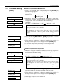
(22) Input Prime Selection
This parameter is to choose whether to enable a reset operation when
INIT signal is ON.
Normally, when the printer receives a reset request signal (nInit signal)
from the host via Centronics interface, the printer will be reset and turn to
the idle state.
When the INPUT PRIME parameter is set to OFF, the printer is reset but
does not turn to idle.
When this parameter is set to ON, the host sends an INIT signal and the
printer turns to idle each time the printer is turned on. If you would like
to avoid this processing, set this parameter to OFF.
When “<2>PARAMETER SET” appears, press the [PAUSE] key until
the following display appears.
<2>PARAMETER SET
INPUT PRIME ON
Use the [FEED] or [RESTART] key to select a desired option.
[RESTART]
INPUT PRIME ON
Available
[FEED]
INPUT PRIME OFF
Unavailable
After selecting the Input Prime, press the [PAUSE] key.
(23) Expansion I/O Interface Type Selection
This parameter is to choose a type of the Expansion I/O interface
operating mode.
This parameter should be set depending on the expansion I/O control
specification of the device to be connected via the expansion I/O
interface. For details, refer to the External Equipment Interface
Specification.
When “<2>PARAMETER SET” appears, press the [PAUSE] key until
the following display appears.
<2>PARAMETER SET
EX.I/O TYPE1
Use the [FEED] or [RESTART] key to select a desired option.
[RESTART]
EX.I/O TYPE1
TYPE1: Standard mode
[FEED]
EX.I/O TYPE2
TYPE2: Inline mode
After selecting an Expansion I/O Interface type, press the [PAUSE] key.
E2-32
2. PRINTER SETUP
ENGLISH VERSION EO1-33057
2.8 Setting an Operating Environment
2.8.1 Parameter Setting
(Cont.)
NOTE:
If the printer and the PC are
connected by USB, plug & play will
be automatically enabled, regardless
of the setting of this parameter.
(24) Plug & Play Selection
This parameter is to choose whether to enable a Plug & Play function.
When “<2>PARAMETER SET” appears, press the [PAUSE] key until
the following display appears.
<2>PARAMETER SET
PLUG & PLAY OFF
Use the [FEED] or [RESTART] key to select a desired option.
[RESTART]
PLUG & PLAY OFF
Unavailable
[FEED]
PLUG & PLAY ON
Available
After selecting a Plug & Play, press the [PAUSE] key.
(25) Label End/Ribbon End Selection
This parameter is to choose a printing process when a label end or ribbon
end is detected.
When “<2>PARAMETER SET” appears, press the [PAUSE] key until
the following display appears.
<2>PARAMETER SET
LBL/RBN END TYP1
Use the [FEED] or [RESTART] key to select a desired option.
LBL/RBN END TYP1
[RESTART]
[FEED]
TYPE1: When a label/ribbon end is
detected in the middle of printing,
printing is immediately paused.
LBL/RBN END TYP2
TYPE2: When a label/ribbon end is detected
in the middle of printing, the printer prints the
half-finished label as far as possible, and
stops when the next label is at the home
position.
After selecting a Label End/Ribbon End type, press the [PAUSE] key.
E2-33
2. PRINTER SETUP
ENGLISH VERSION EO1-33057
2.8 Setting an Operating Environment
2.8.1 Parameter Setting
(Cont.)
(26) Pre-Strip Selection
This parameter is to choose whether to activate the Pre Strip function.
When this parameter is set to ON (Available), the top edge of a label is
separated (pre-stripped) from the backing paper before the label is printed.
This function is intended to make the strip issue easier in case the labels
are hard to strip due to the label intensity, adhesive power, or the printing
speed.
When “<2>PARAMETER SET” appears, press the [PAUSE] key until
the following display appears.
<2>PARAMETER SET
PRE PEEL OFF OFF
Use the [FEED] or [RESTART] key to select a desired option.
[RESTART]
PRE PEEL OFF OFF
Unavailable
[FEED]
PRE PEEL OFF ON
Available
After selecting the Pre Strip, press the [PAUSE] key.
(27) Reverse Feed Speed Selection
This parameter is to choose a reverse feed speed.
In the strip issue, the back feed speed of 3”/sec. may cause a shortage of
feed amount due to a lack of torque, slippery media surface, etc. In such
case, reduce the back feed speed to 2”/sec. to secure the feed amount.
When “<2>PARAMETER SET” appears, press the [PAUSE] key until
the following display appears.
<2>PARAMETER SET
BACK SPEED STD
Use the [FEED] or [RESTART] key to select a desired option.
[RESTART]
BACK SPEED STD
STD: 3 inch/second
[FEED]
BACK SPEED LOW
LOW: 2 inch/second
After selecting the Back Feed Speed, press the [PAUSE] key.
E2-34
2. PRINTER SETUP
ENGLISH VERSION EO1-33057
2.8 Setting an Operating Environment
2.8.1 Parameter Setting
(Cont.)
(28) Maxi Code Specification Selection
This parameter is to choose a Maxi code specification.
When “<2>PARAMETER SET” appears, press the [PAUSE] key until
the following display appears.
<2>PARAMETER SET
MAXI CODE TYPE1
Use the [FEED] or [RESTART] key to select a desired option.
MAXI CODE TYPE1
[RESTART]
[FEED]
TYPE1: Compatible specification
with the B-X series
MAXI CODE TYPE2
TYPE2: Specification for specific
home delivery company
After selecting a Maxi code specification, press the [PAUSE] key.
(29) Strip Motor Torque Selection
This parameter is to choose a strip motor torque.
When “<2>PARAMETER SET” appears, press the [PAUSE] key until
the following display appears.
<2>PARAMETER SET
PEEL OFF TRQ R0
Use the [FEED] or [RESTART] key to select a desired option.
PEEL OFF TRQ R0
R0: Standard
PEEL OFF TRQ R1
R1:
PEEL OFF TRQ R2
R2:
PEEL OFF TRQ R3
R3: PET
[RESTART]
[FEED]
After selecting a strip motor torque, press the [PAUSE] key.
NOTE:
The stabilizer function is available
only to the thermal direct print mode.
(30) Stabilizer Function Selection
This parameter is to choose whether to use the stabilizer function.
The stabilizer function reduces the sound of printing.
When “<2>PARAMETER SET” appears, press the [PAUSE] key until
the following display appears.
<2>PARAMETER SET
STABILIZER ON
Use the [FEED] or [RESTART] key to select a desired option.
[RESTART]
[FEED]
STABILIZER ON
ON: Sound of printing is
reduced.
STABILIZER OFF
OFF: Normal printing
After selecting the stabilizer function, press the [PAUSE] key.
E2-35
2. PRINTER SETUP
ENGLISH VERSION EO1-33057
2.8 Setting an Operating Environment
2.8.2 Dump Mode Setting
While “<4>DUMP MODE” is displayed on the LCD Message Display,
press the [PAUSE] key to enter the Dump Mode.
In the Dump Mode, data in the receive buffer are printed. Data are
expressed in hexadecimal values. This operation allows the user to verify
programming commands or debug the program.
When “<4>DUMP MODE” appears, press the [PAUSE] key.
<4>DUMP MODE
BUFFER RS-232C
Use the [FEED] or [RESTART] key to choose a receive buffer to be
dumped.
BUFFER
RS-232C
BUFFER CENTRO.
[RESTART]
BUFFER
NETWORK
BUFFER
BASIC 1
BASIC Interpreter (Interface → Interpreter buffer)
[FEED]
BUFFER
BASIC 2
BASIC Interpreter (Interpreter → Printer buffer)
BUFFER
USB
After selecting the receive buffer, press the [PAUSE] key.
<4>DUMP MODE
PRINT ON DEMAND
Use the [FEED] or [RESTART] key to select a printing method.
NOTES:
1. When “ON DEMAND” is
selected, it is required to choose a
printing method again and press
the [PAUSE] key to print the
subsequent data until the all data
has been printed.
2 If an error occurs during
dumping, the printer will display
an error message and stop
printing. The error can be
cleared by pressing the [PAUSE]
key, and then the display will
show “<4>DUMP MODE”
again.
After a recovery from the error
the printer will not start printing
automatically.
PRINT ON DEMAND
[RESTART]
[FEED]
Prints 166 lines of data (approx. 50cm), then
stops.
* To print the subsequent data, choose a printing
method again and press the [PAUSE] key.
PRINT ALL
Prints all data in the receive buffer, then stops.
After selecting a printing method, press the [PAUSE] key.
<4>DUMP MODE
NOW PRINTING...
[PAUSE]
<4>DUMP MODE
Turn off the power, and then on.
ON LINE
B-SX8T Vx.x
E2-36
2. PRINTER SETUP
ENGLISH VERSION EO1-33057
2.8 Setting an Operating Environment
2.8.2 Dump Mode Setting
(Cont.)
Print Conditions
• Printing width: 3.9 inches (100 mm)
• Sensor selection: None
• Print speed: 4”/sec.
• Printing mode: Depends on the
selection in use.
• 16 bytes/line
• Data is printed in the order from the
new one to the old one.
• Data specified by the receive buffer
write pointer will be printed in
boldface.
The data in the receive buffer is printed as follows:
00
00
00
7B
30
37
30
2C
30
39
00
00
00
41
7C
34
2C
30
32
7C
00
00
00
58
7D
30
30
2C
30
7D
00
00
00
3B
7B
7C
30
32
2C
7B
00
00
00
2B
44
7D
32
7C
30
4C
00
00
00
30
30
7B
30
7D
30
43
00
00
00
30
37
43
2C
7B
37
3B
00
00
00
30
37
7C
30
4C
30
30
00
00
00
2C
30
7D
30
43
2C
30
00
00
00
2B
2C
7B
33
3B
30
35
00
00
00
30
31
4C
30
30
36
30
00
00
00
30
31
43
2C
30
36
2C
:
:
:
44 45 46 47 48 49 4A 7C 7D 7B 50 43
33 35 30 2C 30 34 30 30 2C 31 2C 31
30 2C 42 3D 41 42 43 44 65 66 67 68
00
00
00
30
30
3B
30
37
30
30
00
00
00
2C
30
30
36
30
2C
30
00
00
00
30
30
33
30
30
2C
30
{AX;+000,+000,+0
0|}{D0760,1100,0
740|}{C|}{LC;003
0,0020,0030,0660
,0,2|}{LC;0070,0
020,0070,0660,0,
9|}{LC;0050,0020
31 30 3B 30
2C 4B 2C 30
69 6A 6B 6C
DEFGHIJ|}{PC10;0
350,0400,1,1,K,0
0,B=ABCDefghijkl
6D 6E 6F 70 7C 7D 7B 50 56 30 32 3B 30
2C 30 36 36 30 2C 30 32 37 30 2C 30 32
41 2C 30 30 2C 42 3D 42 7C 7D 7B 50 56
:
:
:
3B 30 39 30 30 2C 30 31 38 30 2C 54 2C
35 2C 41 2C 30 3D 31 32 33 34 35 36 37
41 42 43 44 45 7C 7D 00 00 00 00 00 00
:
:
00
00
00
2B
2C
30
36
2C
30
32
33 33 30
35 30 2C
30 33 3B
mnop|}{PV02;0330
,0660,0270,0250,
A,00,B=B|}{PV03;
48 2C 30
38 39 30
00 00 00
;0900,0180,T,H,0
5,A,0=1234567890
ABCDE|}
Feed direction
Receive Buffer Size
Interface
Buffer size
RS-232C
1MB (65536 lines)
Centronics
1MB (65536 lines)
Network Interface
1MB (65536 lines)
BASIC 1
8KB (512 lines)
BASIC 2
8KB (512 lines)
USB
1MB (65536 lines)
Required Label Length
Interface
Media length*
RS-232C
198.2m
Centronics
198.2m
Network Interface
198.2m
BASIC 1
2m
BASIC 2
2m
USB
198.2m
*: Media length required for printing all data in the receive buffer.
E2-37
2. PRINTER SETUP
ENGLISH VERSION EO1-33057
2.8 Setting an Operating Environment
2.8.3 BASIC Expansion Mode While “<5>EXPAND MDOE” is displayed on the LCD Message Display,
press the [PAUSE] key to enter the BASIC Expansion Mode.
NOTE:
For the BASIC enable setting mode,
refer to the B-SX6T/SX8T Series Key
Operation Specification stored in the
CD-ROM.
In the BASIC Expansion Mode, it is possible to execute the BASIC
expansion mode program under the following conditions.
•
•
The BASIC expansion mode program has already been loaded.
The BASIC enable setting mode is selected.
The basic expansion mode ends when the basic expansion program is
exited.
When “<5>EXPAND MODE” appears, press the [PAUSE] key.
<5>EXPAND MODE
When the [PAUSE] key is pressed, BASIC program is executed.
E2-38
2. PRINTER SETUP
ENGLISH VERSION EO1-33057
2.8 Setting an Operating Environment
2.8.4 Automatic Calibration
While “<6>AUTO CALIB” is displayed on the LCD Message Display,
press the [PAUSE] key to enter the Automatic Calibration Mode.
In the Automatic Calibration Mode, whether to activate the automatic
calibration at a power on time or not is selectable. When the automatic
calibration is activated, the printer feeds the media for about 160 mm
each time the power is turned on or the Top Cover is opened, to detect a
print start position.
When “<6>AUTO CALIB” appears, press the [PAUSE] key.
<6>AUTO CALIB
OFF
Use the [FEED] or [RESTART] key to select a desired option.
OFF
[RESTART]
ON TRANS.
[FEED]
ON REFLECT
Not activated
Activated
(Feed gap sensor)
Activated
(Black mark sensor)
After selecting the automatic calibration, press the [PAUSE] key.
NOTES:
1. This function is available only when the media pitch is 10.0 mm to 150.0
mm.
2. When this function is activated, the media length, effective print length,
and sensor type specified in the command are ignored.
3. When the printer cannot find a print start position properly, it will
continue to feed the media for up to 500.0 mm. If that does not work, the
printer will stop, resulting in a paper jam.
4. During an automatic calibration, the printer also feeds the ribbon.
E2-39
2. PRINTER SETUP
ENGLISH VERSION EO1-33057
2.8 Setting an Operating Environment
2.8.5 LAN Setting
While “<7>LAN” is displayed on the LCD Message Display, press the
[PAUSE] key to enter the LAN Setting Mode.
In the LAN Setting Mode, whether to enable the LAN communication
and SNMP or not is selectable.
When “<7>LAN” appears, press the [PAUSE] key.
<7>LAN
ON SNMP ON
Use the [FEED] or [RESTART] key to select a desired option.
OFF
[RESTART]
ON SNMP ON
[FEED]
ON SNMP OFF
LAN is disabled.
LAN and SNMP are
enabled
LAN is enabled but
SNMP is disabled.
After selecting the LAN setting, press the [PAUSE] key.
E2-40
2. PRINTER SETUP
ENGLISH VERSION EO1-33057
2.8 Setting an Operating Environment
2.8.6 Real Time Clock Setting While “<8>RTC SET” is displayed on the LCD Message Display, press
the [PAUSE] key to enter the Real Time Clock Setting Mode.
NOTE:
The Real Time Clock Setting is
effective only when an optional Real
Time Clock, B-SA704-RTC-QM-R, is
installed.
The Real Time Clock Setting Mode contains the following sub menus.
Each time the [PAUSE] key is pressed, the sub menus are displayed
sequentially.
(1)
(2)
(3)
(4)
Date setting (Year, Month, Day)
Time setting (Hour, Minute, Second)
Low battery check setting
RTC data renewal timing setting
(1) Date Setting
This parameter is to set the Year, Month, and Day, in order.
When “<8>RTC SET” appears, press the [PAUSE] key.
<8>RTC SET
DATE 05/01/01
Press the [PAUSE] key to set the date.
NOTE:
Use the [FEED] or [RESTART] key
to set the value.
<8>RTC SET
DATE Y 06/01/01
Year
[PAUSE]
<8>RTC SET
DATE M 06/03/01
Month
[PAUSE]
<8>RTC SET
DATE D 06/03/01
Day
After selecting the date, press the [PAUSE] key.
(2) Time Setting
This parameter is to set the Hour, Minute, and Second, in order.
<8>RTC SET
TIME 00/00/00
Press the [PAUSE] key to set the time.
<8>RTC SET
TIME H 10/01/01
Hour
[PAUSE]
<8>RTC SET
TIME M 10/30/01
Minute
[PAUSE]
<8>RTC SET
TIME S 10/30/00
Second
After selecting the time, press the [PAUSE] key.
E2-41
2. PRINTER SETUP
ENGLISH VERSION EO1-33057
2.8 Setting an Operating Environment
2.8.6 Real Time Clock Setting (3) Low Battery Check Setting
This parameter is to choose whether to activate the low battery check
(Cont.)
function or not.
NOTE:
1. Be sure to load the battery and set
the low battery check function to
ON whenever the real time clock
is used. If the battery is not
loaded or the battery voltage is
low, the real time clock data is
erased at the power off time.
2. When the low battery check
function is set to ON and if the
battery voltage is 2.4V or less, the
printer will result in a “LOW
BATTERY” error and stop at the
power on time. In that case, hold
down the [RESTART] key to
restore to “<1>RESET” display.
<8>RTC SET
LOW BATT. CHECK
Press the [PAUSE] key to set.
LOW BATT.
ON
Low battery check is
activated.
LOW BATT.
OFF
Low battery check is not
activated.
[RESTART]
[FEED]
After selecting the low battery check, press the [PAUSE] key.
(4) RTC Data Renewal Timing Setting
This parameter is to choose the RTC data renewal timing.
<8>RTC SET
RENEWAL
Press the [PAUSE] key to set.
RENEWAL
[RESTART]
[FEED]
BATCH
Batch print is possible. However, the same time is
printed on the all media issued in a batch because
the real time clock data is read only for the first
media.
RENEWAL
PAGE
A real time can be printed on each media. However,
the printer needs to stop the motion before printing
each media to read the real time clock data.
After selecting the RTC data renewal timing, press the [PAUSE] key.
The current date is displayed.
<8>RTC SET
DATE 06/03/01
Press the [FEED] and [RESTART] keys at the same time to return to the
<8>RTC SET display.
<8>RTC SET
E2-42
2. PRINTER SETUP
ENGLISH VERSION EO1-33057
2.9 Installing the Printer Drivers
2.9
Installing the Printer Drivers
2.9.1
Introduction
This manual describes how to install the TOSHIBA printer driver for the TOSHIBA bar code printer on your
Windows host computer; install and delete the printer driver, the procedure for adding the LAN port, cautions
and limitations.
The examples provided here illustrate the procedure for installing the printer driver version V7.0 for the B-SA4T
series.
2.9.2
General Description
(1) Features
Once you install the TOSHIBA printer driver on your Windows host computer, you can use the TOSHIBA
bar code printer, as well as the easy-to-use general printers.
You can use this printer by connecting a parallel interface cable (printer cable), a USB cable, or a LAN cable
to your host computer.
(2) System Requirements
To install the TOSHIBA printer driver on your host computer, the following system and environment are
required:
• Operating system:
• Hardware:
• Interface:
Windows 98, Windows Me, Windows 2000, Windows XP
A DOS-/V (IBM PC/AT compatible) machine running an above operating system.
• Parallel interface conforming to the IEEE1284 standard
• USB interface
• LAN interface
E2-43
2. PRINTER SETUP
ENGLISH VERSION EO1-33057
2.9 Installing the Printer Drivers
2.9.3
Installing the Printer Driver
The installation procedure differs depending on the interface connected to the printer and the operation system
you are using. Please install the printer driver by performing the appropriate procedure.
If the previous version of the printer driver has been installed on your host computer , be sure to uninstall it
before you install this printer driver. (Refer to Section 2.9.4 Uninstalling the Printer Driver.)
To print via your network, please install the printer driver by performing the installation procedure for the
parallel interface, and also perform the following:
1. In the procedure, select “LPT1” for the port.
2. After installation of the printer driver is completed, add the LAN port by referring to Section 2.9.5
Adding/Deleting a LAN Port, and specify the LAN port.
(1) Parallel Interface
To use the parallel interface, the following settings are required, after installing the printer driver:
For Windows 98/Me:
Open the printer properties. Select the “Details” tab and click on the
[Spool Settings…] button. The “Spool Settings” dialog box is displayed.
Select “Disable bi-directional support for this printer”.
For Windows 2000/XP:
Open the printer properties and select the “Ports” tab. Mark off the “Enable
bidirectional support” checkbox.
NOTE:
In case of the B-SX4T or B-SX5T series, make sure that the Centronics interface type is set to SPP
(default).
E2-44
2. PRINTER SETUP
ENGLISH VERSION EO1-33057
2.9 Installing the Printer Drivers
Windows 98/Me
(1) Select “Settings” – “Printers” from the “Start” menu to open the printer folder.
(2) Double-click on the “Add Printer” icon. The Add Printer Wizard runs. Click on the [Next] button.
(3) Select “Local printer”, then click on the [Next] button. The screen listing “Manufacturers and
Printers” is displayed.
(4) Click on the [Have Disk…] button. The “Install From Disk” dialog box is displayed.
Specify the “\driver” folder in the CD-ROM drive, then click on the [OK] button.
NOTE:
The latest printer driver is available from the web site, “the Barcode Master”.
(http://www.toshibatec-ris.com/products/barcode/download/index.html)
(5) Select the printer to be installed from “Printers” list, then click on the [Next] button.
Driver name
TEC B-372
Model
B-372-QP
Driver name
TEC B-415
Model
B-415-GH24-QM
B-415-GH25-QM
Driver name
TEC B-419
TEC B-431
B-431-GS10-QP
B-431-GS10-CN
TEC B-452
TEC B-452H
TEC B-472
B-472-QQ
B-472-QQ-US
B-472-GH12-QQ
B-472-QP
B-492L-TH10-QQ
B-492R-TH10-QQ
B-492L-TH10-QP
B-492R-TH10-QP
B-682-TS10-QQ
B-682-TS10-QQ-US
B-682-TS10-QP
B-872-QQ
B-872-QQ-US
B-872-QP
B-SA4TM-TS12-QM-R
B-SA4TP-TS12-QM-R
TEC B-472-CN
B-452-TS10-QQ
B-452-TS10-QQ-US
B-452-TS11-QQ-PAC
B-452-TS12-QP
B-452-TS12-QP-PAC
B-452-TS12-CN
B-472-GH12-CN
B-472-GH14-CN
TEC B-482
B-482-TS10-QQ
B-482-TS10-QQ-US
B-482-TS10-QP
TEC B-572
B-572-QQ
B-572-QQ-US
B-572-QP
TEC B-672
B-672-QQ
B-672-QQ-US
B-672-QP
TEC B-852
B-852-TS12-QQ
B-852-TS12-QQ-US
B-852-TS12-QP
B-882-TS10-QQ
B-882-TS10-QQ-US
B-882-TS10-QP
B-SA4TM-TS12-CN
B-SA4TP-TS12-CN
TEC B-852-R
B-852-TS22-QQ-R
B-852-TS22-QP-R
TEC B-SA4G
B-SA4TM-GS12-QM-R
B-SA4TP-GS12-QM-R
B-SV4D-GS10-QM
B-SV4D-GH10-QM
B-SV4D-GS10-QM-R
B-SV4D-GH10-QM-R
TEC B-SX4
TEC B-492
TEC B-682
TEC B-872
TEC B-SA4T
TEC B-SV4
TEC B-SX5
B-SX5T-TS12-QQ
B-SX5T-TS12-QQ-US
B-SX5T-TS12-QP
B-SX5T-TS22-QQ
B-SX5T-TS22-QQ-US
B-SX5T-TS22-QP
B-SX5T-TS22-QM-R
TEC B-SX8T-R B-SX8T-TS12-QM-R
TEC B-882
TEC B-SA4TCN
B-SX4T-GS10-QQ
B-SX4T-GS10-QQ-US
B-SX4T-GS10-QP
B-SX4T-GS20-QQ
B-SX4T-GS20-QQ-US
B-SX4T-GS20-QP
B-SX4T-GS20-QM-R
TEC B-SX5-CN B-SX5T-TS12-CN
B-SX5T-TS22-CN
TEC CB-416T3
CB-416-T3-QQ
CB-416-T3-QQ-US
CB-416-T3-QP
E2-45
Model
B-419-GS10-QQ
B-419-GS12-QP
B-419-GS12-CN
B-452-HS12-QQ
B-452-HS12-QQ-US
B-452-HS12-QP
B-452-HS12-CN
TEC B-SP2D
B-SP2D-GH20-QM
B-SP2D-GH30-QM
B-SP2D-GH30-QM
B-SP2D-GH20-QM-R
B-SP2D-GH30-QM-R
B-SP2D-GH30-QM-R
TEC B-SX4-CN B-SX4T-GS10-CN
B-SX4T-GS20-CN
TEC B-SX6T-R B-SX6T-TS12-QM-R
TEC CB-426T3
CB-426-T3-QQ
CB-426-T3-QQ-US
CB-426-T3-QP
2. PRINTER SETUP
ENGLISH VERSION EO1-33057
2.9 Installing the Printer Drivers
(6) The screen to select the existing installed printer driver or use the new one, is displayed. Select
“Replace existing driver”, then click on the [Next] button. If you install the printer driver for the first
time, this screen is not displayed.
(7) Select the port to be used for printing from the “Available ports” list, then click on the [Next] button.
(8) Change the printer name if necessary, and select whether or not you use the printer as the default
printer (“Yes” or “No”). Click on the [Finish] button.
(9) The printer driver is installed. When installation is completed, the new printer icon is added in the
“Printers” folder.
E2-46
2. PRINTER SETUP
ENGLISH VERSION EO1-33057
2.9 Installing the Printer Drivers
Windows 2000/XP
(1) Log on to your host computer as a member who has full control access privilege concerning the
printer settings.
(2) Select “Settings” – “Printers” from the “Start” menu to open the printer folder.
(3) Double-click on the “Add Printer” icon. The Add Printer Wizard runs. Click on the [Next] button.
(4) Select “Local printer”. Mark off the “Automatically detect and install my Plug and Play printer”
checkbox, then click on the [Next] button.
(5) Select the port to be used for printing from the “Available ports” list, then click on the [Next] button.
(6) On the screen listing “Manufacturers and Printers”, click on the [Have Disk…] button. The “Install
From Disk” dialog box is displayed.
(7) Specify the “\driver” folder in the CD-ROM drive, then click on the [OK] button.
NOTE:
The latest printer driver is available from the web site, “the Barcode Master”.
(http://www.toshibatec-ris.com/products/barcode/download/index.html)
(8) Select the printer to be installed from “Printers” list, then click on the [Next] button.
Driver name
TEC B-372
Model
B-372-QP
Driver name
TEC B-415
Model
B-415-GH24-QM
B-415-GH25-QM
Driver name
TEC B-419
TEC B-431
B-431-GS10-QP
B-431-GS10-CN
TEC B-452
TEC B-452H
TEC B-472
B-472-QQ
B-472-QQ-US
B-472-GH12-QQ
B-472-QP
B-492L-TH10-QQ
B-492R-TH10-QQ
B-492L-TH10-QP
B-492R-TH10-QP
B-682-TS10-QQ
B-682-TS10-QQ-US
B-682-TS10-QP
B-872-QQ
B-872-QQ-US
B-872-QP
B-SA4TM-TS12-QM-R
B-SA4TP-TS12-QM-R
TEC B-472-CN
B-452-TS10-QQ
B-452-TS10-QQ-US
B-452-TS11-QQ-PAC
B-452-TS12-QP
B-452-TS12-QP-PAC
B-452-TS12-CN
B-472-GH12-CN
B-472-GH14-CN
TEC B-482
B-482-TS10-QQ
B-482-TS10-QQ-US
B-482-TS10-QP
TEC B-572
B-572-QQ
B-572-QQ-US
B-572-QP
TEC B-672
B-672-QQ
B-672-QQ-US
B-672-QP
TEC B-852
B-852-TS12-QQ
B-852-TS12-QQ-US
B-852-TS12-QP
B-882-TS10-QQ
B-882-TS10-QQ-US
B-882-TS10-QP
B-SA4TM-TS12-CN
B-SA4TP-TS12-CN
TEC B-852-R
B-852-TS22-QQ-R
B-852-TS22-QP-R
TEC B-SA4G
B-SA4TM-GS12-QM-R
B-SA4TP-GS12-QM-R
B-SV4D-GS10-QM
B-SV4D-GH10-QM
B-SV4D-GS10-QM-R
B-SV4D-GH10-QM-R
TEC B-SX4
TEC B-492
TEC B-682
TEC B-872
TEC B-SA4T
TEC B-SV4
TEC B-SX5
B-SX5T-TS12-QQ
B-SX5T-TS12-QQ-US
B-SX5T-TS12-QP
B-SX5T-TS22-QQ
B-SX5T-TS22-QQ-US
B-SX5T-TS22-QP
B-SX5T-TS22-QM-R
TEC B-SX8T-R B-SX8T-TS12-QM-R
TEC B-882
TEC B-SA4TCN
B-SX4T-GS10-QQ
B-SX4T-GS10-QQ-US
B-SX4T-GS10-QP
B-SX4T-GS20-QQ
B-SX4T-GS20-QQ-US
B-SX4T-GS20-QP
B-SX4T-GS20-QM-R
TEC B-SX5-CN B-SX5T-TS12-CN
B-SX5T-TS22-CN
TEC CB-416T3
CB-416-T3-QQ
CB-416-T3-QQ-US
CB-416-T3-QP
E2-47
Model
B-419-GS10-QQ
B-419-GS12-QP
B-419-GS12-CN
B-452-HS12-QQ
B-452-HS12-QQ-US
B-452-HS12-QP
B-452-HS12-CN
TEC B-SP2D
B-SP2D-GH20-QM
B-SP2D-GH30-QM
B-SP2D-GH30-QM
B-SP2D-GH20-QM-R
B-SP2D-GH30-QM-R
B-SP2D-GH30-QM-R
TEC B-SX4-CN B-SX4T-GS10-CN
B-SX4T-GS20-CN
TEC B-SX6T-R B-SX6T-TS12-QM-R
TEC CB-426T3
CB-426-T3-QQ
CB-426-T3-QQ-US
CB-426-T3-QP
2. PRINTER SETUP
ENGLISH VERSION EO1-33057
2.9 Installing the Printer Drivers
(9) The “Use Existing Driver” screen is displayed. Select “Replace existing driver”, then click on the
[Next] button. If you install the printer driver for the first time, this screen is not displayed.
(10) Change the printer name if necessary, and select whether or not you use the printer as the default
printer (“Yes” or “No”). Click on the [Next] button.
(11) Select whether or not the printer will be shared with other network users (“Shared” or “Not shared”).
Click on the [Next] button.
(12) Select whether or not the test page will be printed (“Yes” or “No”), then click on the [Finish] button.
(13) If the “Digital Signature Not Found” screen is displayed, click on the [Yes] button.
(14) When the “Completing the Add Printer Wizard” screen is displayed, click on the [Finish] button.
(15) When installation is completed, the new printer icon is added in the “Printers” folder.
E2-48
2. PRINTER SETUP
ENGLISH VERSION EO1-33057
2.9 Installing the Printer Drivers
(2) USB INTERFACE
Installation starts by the operating system’s plug-and-play function.
Windows 98/Me
(1) Turn the printer ON, then connect it to your host computer with the USB cable.
The “New Hardware Found” dialog box is displayed, and “USB Device” is detected.
(2) After a while, the “Add New Hardware Wizard” dialog box is displayed.
Select “Specify the location of the driver (Advanced)”, then click on the [Next] button.
E2-49
2. PRINTER SETUP
ENGLISH VERSION EO1-33057
2.9 Installing the Printer Drivers
(3) Select “Search for the best driver for your device. (Recommended)”.
Mark the “Specify a location” checkbox, then click on the [Browse] button.
Specify “\driver” folder, then click on the [Next] button.
(4) Check to see that the “USB Printing Support” driver is detected, then click on the [Next] button.
E2-50
2. PRINTER SETUP
ENGLISH VERSION EO1-33057
2.9 Installing the Printer Drivers
(5) When the screen which indicates the USB Printing Support driver has been installed, is
displayed, click on the [Finish] button.
(6) After a while, “TEC B-SA4T” is detected as a new hardware.
(7) The “Add New Hardware Wizard” dialog box is displayed.
Select “Specify the location of the driver (Advanced)”, then click on the [Next] button.
E2-51
2. PRINTER SETUP
ENGLISH VERSION EO1-33057
2.9 Installing the Printer Drivers
(8) Select “Search for the best driver for your device. (Recommended)”.
Mark the “Specify a location” checkbox, then click on the [Browse] button.
Specify “\driver” folder, then click on the [Next] button.
(9) Check to see that the “TEC B-SA4T” driver is detected, then click on the [Next] button.
E2-52
2. PRINTER SETUP
ENGLISH VERSION EO1-33057
2.9 Installing the Printer Drivers
(10) Change the printer name if necessary, and select whether or not you use the printer as the default
printer (“Yes” or “No”). Click on the [Finish] button.
(11) When the screen, which indicates TEC B-SA4T has been installed, is displayed, click on the
[Finish] button.
(12) When installation is completed, the new printer icon is added in the “Printers” folder.
E2-53
2. PRINTER SETUP
ENGLISH VERSION EO1-33057
2.9 Installing the Printer Drivers
Windows 2000/XP
NOTE:
When plug-and-play printer installation in progress is stopped, be sure to delete the printer detected and
displayed on the “Device Manager” tab of the “System Properties” dialog box.
(1) Log on to your host computer as a member who has full control access privilege concerning the
printer settings.
(2) Turn the printer ON, then connect it to your host computer with the USB cable.
(3) “USB Device” is automatically detected, and “USB Printing Support” is automatically installed.
(4) After a while, for Windows XP, “TEC B-SA4T” is detected as a new device.
For Windows 2000, “Unknown” device is detected as a new device. In both cases, perform the
following steps, though dialog boxes for Windows XP are used.
(5) The “Found New Hardware Wizard” dialog box is displayed.
Select “No, not this time”, then click on the [Next] button.
E2-54
2. PRINTER SETUP
ENGLISH VERSION EO1-33057
2.9 Installing the Printer Drivers
(6) Select “Install from a list or specific location (Advanced)”, then click on the [Next] button.
(7) Select “Search for the best driver in these locations”.
Mark the “Include this location in the search” checkbox, then click on the [Browse] button.
Specify the “\driver” folder in the CD-ROM, then click on the [Next] button.
E2-55
2. PRINTER SETUP
ENGLISH VERSION EO1-33057
2.9 Installing the Printer Drivers
(8) When the dialog box below is displayed, click on the [Continue Anyway] button.
(9) When the “Completing the Found New Hardware Wizard” screen is displayed, click on the
[Finish] button.
(10) When installation is completed, the new printer icon is added in the “Printers” folder.
E2-56
2. PRINTER SETUP
ENGLISH VERSION EO1-33057
2.9 Installing the Printer Drivers
2.9.4
Uninstalling the Printer Driver
NOTE:
Before uninstalling the printer driver, be sure to complete all of printing, the status monitor, and properties settings.
Windows 98/ME
(1) Select “Settings” – “Printers” from the “Start” menu to open the printer folder.
(2) Right-click on the printer driver icon to be deleted, then select “Delete”. The confirmation message is
displayed.
(3) Click on the [Yes] button to delete.
(4) After the printer driver icon is deleted, restart your host computer.
Windows 2000/XP
(1) Log on to your host computer as a member who has full control access privilege concerning the
printer settings.
(2) Select “Settings” – “Printers” from the “Start” menu to open the printer folder.
(3) Right-click on the printer driver icon to be deleted, then select “Delete”. The confirmation message is
displayed.
(4) Click on the [Yes] button to delete.
(5) After the printer icon is deleted, select “Server Properties” from “File” menu of the “Printers” folder.
(6) Select the printer driver to be deleted, then click on the [Remove] button. After the printer driver is
deleted, restart your host computer.
E2-57
2. PRINTER SETUP
ENGLISH VERSION EO1-33057
2.9 Installing the Printer Drivers
2.9.5
Adding/Deleting a LAN Port
To use the LAN interface, first, you have to make the following settings in “<7> IP ADDRESS” in the system
mode of the printer. (Refer to TOSHIBA TEC support representative.)
• Set the printer IP address (“PRINTER IP ADRES”), the gateway IP address (“GATEWAY IP
ADRES”), and subnet mask (“SUBNET MASK”).
• Set the port number (“SOCKET PORT”).
Among these settings, the printer IP address and the port number are also required for adding a LAN port.
(1) Adding a LAN Port
Windows 98/ME
(1) Right-click on the printer icon. Select “Properties” to open the printer “Properties” dialog box.
(2) Select the “Details” tab, and click on the [Add Port…] button. The “Add Port” dialog box is
displayed.
(3) Select “Other”.
Select “Seagull Scientific TCP/IP Port” from the list, then click on the [OK] button.
(4) On the “Add Seagull TCP/IP Port” dialog box, enter the name or IP address, the port number, and the
port name. For the IP address and the port number, enter the same ones as you have set in “<7> IP
ADDRESS” in the system mode of the printer. After entering these, click on the [OK] button.
(5) When addition of the port is completed, the port is added to the drop down list for “Print to the
following port”.
E2-58
2. PRINTER SETUP
ENGLISH VERSION EO1-33057
2.9 Installing the Printer Drivers
Windows 2000/XP
(1) Right-click on the printer icon. Select “Properties” to open the printer “Properties” dialog box.
(2) Select the “Ports” tab, and click on the [Add Port…] button. The “Printer Ports” dialog box is
displayed.
(3) Select “Seagull Scientific TCP/IP Port” from the “Available Printer Ports” list, then click on the [OK]
button.
(4) On the “Add Seagull TCP/IP Port” dialog box, enter the name or IP address, the port number, and the
port name. For the IP address and the port number, enter the same ones as you have set in “<7> IP
ADDRESS” in the system mode of the printer. After entering these, click on the [OK] button.
(5) When addition of the port is completed, the port is added to the “Print to the following port(s)” list.
(2) Deleting a LAN Port
NOTE:
Before deleting a port, be sure to check if other printers also use it. If there are printers which use the port to
be deleted, change their port to another, before deleting the port.
Windows 98/ME
(1) Right-click on the printer icon. Select “Properties” to open the printer “Properties” dialog box.
(2) Select the “Details” tab, and click on the [Delete Port…] button.
(3) Select the port to be deleted, then click on the [OK] button.
(4) When deletion of the port is completed, the port is also deleted from the “Print to the following port”
list.
Windows 2000/XP
(1) Right-click on the printer icon. Select “Properties” to open the printer “Properties” dialog box.
(2) On the “Ports” tab, select the port to be deleted, then click on the [Delete Port] button.
(3) When deletion of the port is completed, the port is also deleted from the “Print to the following
port(s)” list.
E2-59
2. PRINTER SETUP
ENGLISH VERSION EO1-33057
2.9 Installing the Printer Drivers
2.9.6
Cautions
(1) Printer Driver Upgrades
• To upgrade the printer driver to this version, uninstall the previous version of the printer driver, before
installing this printer driver.
• Be sure to restart your host computer, after you upgrade the printer driver.
• When your operating system is Windows 98, or Windows Me, be sure to restart your host computer,
after you uninstall the previous version of the printer driver. Or, the printer driver is not upgraded
properly.
(2) Others
• If your operating system is Windows 2000 or Windows XP, when plug-and-play printer installation in
progress is stopped, be sure to delete the printer detected and displayed on the “Device Manager” tab of
the “System Properties” dialog box.
• Before uninstalling the printer driver, be sure to complete all of printing, the status monitor, and
properties settings.
• Before deleting a port, be sure to check if other printers also use it. If there are printers which use the
port to be deleted, change their port to another, before deleting the port.
E2-60
2. PRINTER SETUP
ENGLISH VERSION EO1-33057
2.9 Installing the Printer Drivers
2.9.7
Using the Printer Driver
For how to use the Printer Driver, please refer to the Help for Windows Printer Drivers screen.
1)
Open the Properties screen of the Printer Driver.
2)
Clicking on the About tab causes the following screen to appear.
Click on the [Help] button.
About tab
[Help] button
3)
The Help for Windows Printer Drivers screen appears. This screen will provide how to use the printer
driver.
E2-61
2. PRINTER SETUP
ENGLISH VERSION EO1-33057
2.10 Print Test
2.10 Print Test
After your operating environment has been set, perform a print test.
1. Perform a print test by using the Printer Driver or an Issue Command.
The printer driver’s Properties screen allows you to set the
communication conditions, media size, and other printing conditions
in accordance with your operating environment. For details, refer to
the Help for the Windows Printer Drivers screen.
Example: Stock tab display of the Printer Driver’s Properties Screen
Print Method
Sensor
Label Gap
Issue Mode
Cut
Print Speed
Fine Adjustment
Print Method:
Sensor:
Issue Mode:
Cut:
Fine Adjustment:
Direct thermal or thermal transfer is selectable.
Media sensor type is selectable.
Batch or strip is selectable.
Whether to use the cutter or not is selectable.
Adjustment values for the feed amount, cut/strip
position, etc. can be set.
2. Confirm the print test result.
•
When a print start position, cut/strip position, or print tone needs to
be adjusted: ⇒ Section 2.11 Position and Print Tone Fine
Adjustment
•
When pre-printed media is used, and if a print start position is not
properly detected: ⇒ Section 2.12 Threshold Setting
E2-62
2. PRINTER SETUP
ENGLISH VERSION EO1-33057
2.10 Print Test
2.10 Print Test (Cont.)
When using an optional Cutter Module or Strip Module
It is necessary to set the issue mode, cut/strip position, etc. for the Printer
Driver or TPCL (TEC Printer Command Language) in accordance with
your printing condition.
For details of the TPCL, refer to the B-SX6T/SX8T Series External
Equipment Interface Specification stored in the CD-ROM.
Regarding how to use the Printer Driver, refer to the Help for the
Windows Printer Drivers screen.
To gain maximum performance and life from the Cutter Module or Strip
Module, periodic cleaning is required.
Before starting a cleaning, be sure to TURN OFF the printer to avoid risk
of injury.
For details of cleaning, refer to Section 4.1.5 Optional Cutter Module
or Section 4.1.6 Optional Strip Module.
E2-63
2. PRINTER SETUP
ENGLISH VERSION EO1-33057
2.11 Position and Print Tone Fine Adjustment
2.11 Position and Print
Tone Fine
Adjustment
This section describes how to fine adjust a print start position, cut/strip
position, reverse feed amount, print tone, and ribbon motor torque.
When a fine adjustment is required, such as print start position, print tone,
etc, follow the procedure below.
1. Turn on the printer and confirm that “ONLINE” appears on the LCD
Message Display.
2. Press the [PAUSE] key to pause the printer.
3. Hold down the [RESTART] key for three seconds until “<1>RESET”
is displayed.
4. Press the [FEED] or [RESTART] key until “<3>ADJUST SET”
appears on the LCD Message Display.
5. When “<3>ADJUST SET” appears, press the [PAUSE] key to enter
the Parameter Fine Adjustment Mode.
<3>ADJUST SET
[PAUSE]
<3>ADJUST SET
FEED ADJ.+10.0mm
[PAUSE]
<3>ADJUST SET
CUT ADJ. +10.0mm
[PAUSE]
<3>ADJUST SET
BACK ADJ. +5.0mm
[PAUSE]
<3>ADJUST SET
X ADJUST +50.0mm
[PAUSE]
<3>ADJUST SET
TONE ADJ.<T> +3
[PAUSE]
<3>ADJUST SET
TONE ADJ.<D> -2
[PAUSE]
<3>ADJUST SET
RBN ADJ <FW> -10
[PAUSE]
<3>ADJUST SET
RBN ADJ <BK> -5
[PAUSE]
<3>ADJUST SET
THRESHOLD<R>1.0V
The Parameter Fine Adjustment Mode contains the following sub menus.
Each time the [PAUSE] key is pressed, the sub menus are displayed
sequentially.
(1) Feed Amount Fine Adjustment:
Feed amount to the print start position is fine adjusted.
(2) Cut/Strip Position Fine Adjustment:
Cut position or strip position is fine adjusted.
(3) Reverse Feed Amount Fine Adjustment:
Reverse feed amount is fine adjusted.
(4) X-coordinate Fine Adjustment:
X-coordinate of a print position is fine adjusted.
(5) Print Tone Fine Adjustment (Thermal transfer):
Print tone is fine adjusted for thermal transfer mode.
(6) Print Tone Fine Adjustment (Thermal direct):
Print tone is fine adjusted for thermal direct mode.
(7) Ribbon Motor Drive Voltage Fine Adjustment (Take-up
motor):
Drive voltage of the ribbon take-up motor is fine adjusted.
(8) Ribbon Motor Drive Voltage Fine Adjustment (Feed motor)
Drive voltage of the ribbon feed motor is fine adjusted.
(9) Threshold Fine Adjustment (Black mark sensor):
Threshold for the black mark sensor is fine adjusted. See Section
2.12.
(10) Threshold Fine Adjustment (Feed gap sensor):
Threshold for the feed gap sensor is fine adjusted. See Section
2.12.
NOTE:
The printer driver’s properties screen also has Parameter Fine Adjustment
menu.
[PAUSE]
<3>ADJUST SET
THRESHOLD<T>1.4V
[PAUSE]
E2-64
2. PRINTER SETUP
ENGLISH VERSION EO1-33057
2.11 Position and Print Tone Fine Adjustment
2.11 Position and Print
Tone Fine
Adjustment (Cont.)
Print Start Position Fine Adjustment
<3>ADJUST SET
FEED ADJ.+10.0mm
FEED ADJ.+50.0mm
NOTES:
Choose a desired value by using the
[RESTART] or [FEED] key.
Pressing the [FEED] key one time
causes a –0.1mm change, up to
–50.0 mm.
Pressing the [RESTART] key one
time causes a +0.1mm change, up
to +50.0 mm.
[RESTART]
FEED ADJ.+49.9mm
FEED ADJ.+0.1mm
FEED ADJ.+0.0mm
FEED ADJ.-0.1mm
[FEED]
FEED ADJ.-49.9mm
FEED ADJ.-50.0mm
After selecting a fine adjustment value, press the [PAUSE] key.
• Example of Print Start Position Fine Adjustment
When setting +3.0 mm
Compared with “+0.0mm” position, the print start
position is shifted forward.
Feed Direction
One label
Print Start Position
3mm
When setting +0.0 mm
Feed Direction
When setting –3.0 mm
Compared with “+0.0mm” position, the print start
position is shifted backward.
One label
Print Start Position
3mm
Feed Direction
One label
Print Start Position
E2-65
2. PRINTER SETUP
ENGLISH VERSION EO1-33057
2.11 Position and Print Tone Fine Adjustment
2.11 Position and Print
Tone Fine
Adjustment (Cont.)
NOTES:
Choose a desired value by using the
[RESTART] or [FEED] key.
Pressing the [FEED] key one time
causes a –0.1mm change, up to
–50.0 mm.
Pressing the [RESTART] key one
time causes a +0.1mm change, up
to +50.0 mm.
Cut/Strip Position Fine Adjustment
<3>ADJUST SET
CUT ADJ. +10.0mm
CUT ADJ.+50.0mm
[RESTART]
CUT ADJ.+49.9mm
CUT ADJ.+0.1mm
CUT ADJ.+0.0mm
CUT ADJ.-0.1mm
[FEED]
CUT ADJ.-49.9mm
CUT ADJ.-50.0mm
After selecting a fine adjustment value, press the [PAUSE] key.
• Example of Cut Position Fine Adjustment
When setting +3.0 mm
Compared with “+0.0mm” position, the cut position
is shifted forward.
Feed Direction
3mm
Cut Position
When setting +0.0 mm
Feed Direction
Cut Position
3mm
When setting –3.0 mm
Compared with “+0.0mm” position, the cut position
is shifted backward.
Feed Direction
Cut Position
E2-66
2. PRINTER SETUP
ENGLISH VERSION EO1-33057
2.11 Position and Print Tone Fine Adjustment
• Example of Strip Position Fine Adjustment
When setting +3.0 mm
Compared with “+0.0mm” position, the stop position
after printing is shifted forward.
Print Head
Label
Platen
Strip Plate
Backing Paper
Stop position after
printing
3mm
When setting +0.0 mm
Stop position after
printing
3mm
When setting –3.0 mm
Compared with “+0.0mm” position, the stop position
after printing is shifted backward.
Stop position after
printing
E2-67
2. PRINTER SETUP
ENGLISH VERSION EO1-33057
2.11 Position and Print Tone Fine Adjustment
2.11 Position and Print
Tone Fine
Adjustment (Cont.)
NOTES:
Choose a desired value by using the
[RESTART] or [FEED] key.
Pressing the [FEED] key one time
causes a –0.1mm change, up to
–9.9 mm.
Pressing the [RESTART] key one
time causes a +0.1mm change, up
to +9.9 mm.
Reverse Feed Amount Fine Adjustment
<3>ADJUST SET
BACK ADJ. +5.0mm
BACK ADJ.+9.9mm
[RESTART]
BACK ADJ.+9.8 mm
BACK ADJ.+0.1mm
BACK ADJ.+0.0mm
BACK ADJ.-0.1mm
[FEED]
BACK ADJ.-9.8mm
BACK ADJ.-9.9mm
After selecting a fine adjustment value, press the [PAUSE] key.
• Example of Reverse Feed Amount Fine Adjustment
When setting +3.0 mm
Compared with “+0.0mm” position, the print start position
after a reverse feed is shifted forward.
Feed Direction
Print Start Position after a
reverse feed
3mm
When setting +0.0 mm
Feed Direction
When setting –3.0 mm
Compared with “+0.0mm” position, the print start position
after a reverse feed is shifted backward.
Print Start Position after a
reverse feed
3mm
Feed Direction
Print Start Position after a
reverse feed
E2-68
2. PRINTER SETUP
ENGLISH VERSION EO1-33057
2.11 Position and Print Tone Fine Adjustment
2.11 Position and Print
Tone Fine
Adjustment (Cont.)
NOTES:
Choose a desired value by using the
[RESTART] or [FEED] key.
Pressing the [FEED] key one time
causes a –0.1mm change, up to
–99.9 mm.
Pressing the [RESTART] key one
time causes a +0.1mm change, up
to +99.9 mm.
X Coordinate Fine Adjustment
<3>ADJUST SET
X ADJUST +5.0mm
X ADJUST +99.9mm
[RESTART]
X ADJUST +99.8mm
X ADJUST +0.1mm
X ADJUST +0.0mm
X ADJUST -0.1mm
[FEED]
X ADJUST -99.8mm
X ADJUST -99.9mm
After selecting a fine adjustment value, press the [PAUSE] key.
Feed Direction
• Example of X Coordinate Fine Adjustment
Top Down Printing
When setting –50.0 mm
Compared with “+0.0mm” position, the print position
Y
is shifted to the left.
X
ABC
Y
Bottom First Printing
50.0mm
When setting +0.0 mm
X
ABC
When setting +50.0 mm
Compared with “+0.0mm” position, the print position
is shifted to the right.
50.0mm
ABC
E2-69
2. PRINTER SETUP
ENGLISH VERSION EO1-33057
2.11 Position and Print Tone Fine Adjustment
2.11 Position and Print
Tone Fine
Adjustment (Cont.)
Print Tone Fine Adjustment
Thermal Transfer Print
<3>ADJUST SET
TONE ADJ.<T> +3
NOTES:
Choose a desired value by using the
[RESTART] or [FEED] key.
Pressing the [FEED] key one time
causes a –1 tone change, up to
–10 tones.
Pressing the [RESTART] key one
time causes a +1 tone change, up to
+10 tones.
TONE ADJ<T>. +10
[RESTART]
TONE ADJ<T>. +9
TONE ADJ<T>. +0
[FEED]
Darker
Standard
TONE ADJ<T>. -9
TONE ADJ<T>. -10
Lighter
After selecting a fine adjustment value or to skip this menu, press the
[PAUSE] key.
Thermal Direct Print
<3>ADJUST SET
TONE ADJ.<D> -2
TONE ADJ<D>. +10
[RESTART]
TONE ADJ<D>. +9
TONE ADJ<D>. +0
[FEED]
Darker
Standard
TONE ADJ<D>. -9
TONE ADJ<D>. -10
Lighter
After selecting a fine adjustment value or to skip this menu, press the
[PAUSE] key.
E2-70
2. PRINTER SETUP
ENGLISH VERSION EO1-33057
2.11 Position and Print Tone Fine Adjustment
2.11 Position and Print
Tone Fine
Adjustment (Cont.)
Ribbon Motor Voltage Fine Adjustment
When the ribbon is slack or wrinkled and printing is affected, fine adjust
the ribbon motor torque by using the following procedure.
Take-up Motor (RBN ADJ <FW>)
NOTES:
Choose a desired value by using the
[RESTART] or [FEED] key.
Pressing the [FEED] key one time
causes a –1 step change, up to
–15 steps.
Pressing the [RESTART] key one
time causes a +1 step change, up to
+0 steps.
<3>ADJUST SET
RBN ADJ<FW> -10
High
RBN ADJ<FW> +0
[RESTART]
RBN ADJ<FW> -1
RBN ADJ<FW> -2
[FEED]
Motor Torque
RBN ADJ<FW> -14
RBN ADJ<FW> -15
Low
After selecting a fine adjustment value or to skip this menu, press the
[PAUSE] key.
Feed Motor (RBN ADJ <BK>)
NOTES:
Choose a desired value by using the
[RESTART] or [FEED] key.
Pressing the [FEED] key one time
causes a –1 step change, up to
–15 steps.
Pressing the [RESTART] key one
time causes a +1 step change, up to
+10 steps.
<3>ADJUST SET
RBN ADJ<BK> -5
High
RBN ADJ<BK> +10
[RESTART]
RBN ADJ<BK> +9
Motor Torque
RBN ADJ<BK> +8
[FEED]
RBN ADJ<BK> -14
RBN ADJ<BK> -15
Low
After selecting a fine adjustment value or to skip this menu, press the
[PAUSE] key.
E2-71
2.PRINTER SETUP
ENGLISH VERSION EO1-33057
2.12 Threshold Setting
2.12 Threshold Setting
To maintain a constant print position the printer uses the media sensor to
detect a print start position according to the difference of voltage between
a print area and a gap or black mark. When the media is pre-printed, the
darker (or more dense) inks can interfere with this process causing paper
jam errors.
To get around this problem, first, try an automatic threshold setting.
If the problem still occurs, then, the threshold voltage needs to be
manually set.
Automatic threshold setting procedure
1. Turn the power ON. The printer is in online mode.
2. Load a pre-printed media roll.
When using a label stock, move the Feed Gap Sensor so that it is in
line with the centre of the label.
When using a tag stock, move the Black Mark Sensor so that it is in
line with the centre of a black mark.
3. Press the [PAUSE] key.
4. The printer enters the pause mode.
5. Press and hold the [PAUSE] key in the pause state until the following
screen appears.
6. The sensor type is displayed.
TRANSMISSIVE
B-SX8T
V1.0A
7.
Select the sensor to be adjusted by using the [FEED] key.
REFLECTIVE
B-SX8T
V1.0A
Black mark sensor
NOTES:
1. Failure to feed more than 1.5
labels may result in an incorrect
threshold setting.
2. While the Top Cover is raised,
the [PAUSE] key does not work
3. A paper end error cannot be
detected during paper feed.
8.
[FEED]
TRANSMISSIVE
B-SX8T
V1.0A
Feed gap sensor
Press and hold the [PAUSE] key until more than 1.5 labels (tags)
have been issued.
The media will continue to be fed until the [PAUSE] key is released.
(An automatic threshold setting for the selected sensor is completed
by this operation.)
PAUSE
B-SX8T
V1.0A
9. Press the [RESTART] key.
ON LINE
B-SX8T
V1.0A
10. The printer returns to online mode.
Send an issue command from the host computer to the printer.
E2-72
2.PRINTER SETUP
ENGLISH VERSION EO1-33057
2.12 Threshold Setting
2.12 Threshold Setting
(Cont.)
Manual threshold setting procedure
If a paper jam error still occurs even after an automatic threshold setting
has been performed, manually set the threshold voltage.
To make a threshold value manually set in this section effective, select
the Transmissive Sensor (when using manual threshold value) or
Reflective Sensor (when using manual threshold value) within software
commands or the printer driver.
1. While holding down the [FEED] and [PAUSE] keys, turn on the
printer.
2. When “<1>DIAG.” appears on the LCD Message Display, release the
[FEED] and [PAUSE] keys.
<1>DIAG.
Now, the printer is in the System Mode for system administrators.
<5>SENSOR ADJ.
[PAUSE]
3. Press the [FEED] or [RESTART] key until “<5>SENSOR ADJ.”
appears on the LCD Message Display.
<5>SENSOR ADJ.
<5>SENSOR ADJ.
[H]28°C [A]28°C
[PAUSE]
<5>SENSOR ADJ.
[REFLECT] 3.5V
4. Press the [PAUSE] key to enter the Sensor Adjustment Mode.
<5>SENSOR ADJ.
[H]28°C [A]28°C
[FEED] or [RESTART]
<5>SENSOR ADJ.
[REFLECT] 4.8V*
[PAUSE]
<5>SENSOR ADJ.
[TRANS.] 2.4V
[FEED] or [RESTART]
<5>SENSOR ADJ.
[TRANS.] 4.1V*
[PAUSE]
<5>SENSOR ADJ.
[PE]R0.1V T4.8V
[FEED] or [RESTART]
<5>SENSOR ADJ.
[PE]R0.1V T4.8V*
[PAUSE]
<5>SENSOR ADJ.
[RIBBON] 3.1V
[FEED] or [RESTART]
<5>SENSOR ADJ.
[RIBBON] 3.1V*
[PAUSE]
The Sensor Adjustment Mode contains sub menus for displaying the
current status of each sensor and for storing “media level” voltage and
“no media level” voltage. Each time the [PAUSE] key is pressed, the
sub menus are displayed sequentially.
(1) Sensor Status Display:
Temperatures being detected by the Print Head Thermistor and
the Ambient Thermistor are displayed.
(2) Black Mark Sensor Status Display:
Voltage being detected by the Black Mark Sensor is displayed.
(3) Black Mark Sensor Adjustment:
Using the media actually used, a “media level” voltage is stored.
(4) Feed Gap Sensor Status Display:
Voltage being detected by the Feed Gap Sensor is displayed.
(5) Feed Gap Sensor Adjustment:
Using the media actually used, a “media level” voltage is stored.
(6) Black Mark Sensor/Feed Gap Sensor Status Display (No
media):
“No media level” voltage detected by the Black Mark
Sensor/Feed Gap Sensor is displayed.
(7) Black Mark Sensor/Feed Gap Sensor Adjustment (No
media):
“No media level” voltage is stored.
(8) Ribbon End Sensor Status Display:
Voltage being detected by the Ribbon End Sensor is displayed.
(9) Ribbon End Sensor Adjustment:
Using the ribbon actually used, a “ribbon level” voltage is stored.
E2-73
2.PRINTER SETUP
ENGLISH VERSION EO1-33057
2.12 Threshold Setting
2.12 Threshold Setting
(Cont.)
When using the Black Mark Sensor
(1) While “<5>SENSOR ADJ.” is displayed, press the [PAUSE] key
until the message appears.
The displayed value is a real-time voltage being detected by the Black
Mark Sensor.
<5>SENSOR ADJ.
[REFLECT] 3.5V
Voltage at a black mark
Midpoint (Threshold voltage)
Voltage at a print area
<5>SENSOR ADJ.
[REFLECT] 3.5V
<5>SENSOR ADJ.
[REFLECT] 4.8V*
<5>SENSOR ADJ.
[TRANS.] 2.4V
(2) Measure a voltage at a blank part of media and a black mark,
respectively. At this time, write down the midpoint between both
voltages. (This value is used later for a threshold setting.)
(Example)
Print area = 4.8V, Black mark = 2.4V
Midpoint = 3.6V
NOTES:
1. When measuring a voltage of a blank area, be careful not to align a
pre-print with the sensor by mistake.
2. Confirm that there is at least 0.7V difference between the two values.
If the difference in voltage is less than 0.7V, a print start position
cannot be detected. In that case, please consider changing the media
type.
3. Make sure that the Top Cover is closed when measuring the voltages.
(3) Press and hold the [RESTART] or [FEED] key for about 3 seconds
aligning a blank part of print area with the Black Mark Sensor.
(4) When storing a “media level” voltage is completed, an asterisk “*”is
displayed on the right side of a voltage. Press the [PAUSE] key.
(5) A real-time voltage being detected by the Feed Gap Sensor is
displayed.
When using the Feed Gap Sensor
Voltage at a label gap
Midpoint (Threshold voltage)
Voltage at a print area
<5>SENSOR ADJ.
[TRANS.] 2.4V
<5>SENSOR ADJ.
[TRANS.] 2.4V*
<5>SENSOR ADJ.
[PE]R0.1V T4.8V
(1)Measure a voltage at a blank part of label and a label gap, respectively.
At this time, write down the midpoint of both voltages. (This value is
used later for a threshold setting.)
(Example)
Print area = 2.4V, Gap = 4.0V
Midpoint = 3.2V
NOTES:
1. When measuring a voltage at a blank area, be careful not to align a
pre-print with the sensor by mistake.
2. Confirm that there is at least 0.7V difference between the two values.
If the difference in voltage is less than 0.7V, a print start position
cannot be detected. In that case, please consider changing the media
type.
3. Make sure that the Top Cover is closed when measuring the voltages.
(2) Press and hold the [RESTART] or [FEED] key for about 3 seconds
aligning a blank part of print area with the Feed Gap Sensor.
(3) When storing a “media level” voltage is completed, an asterisk “*”is
displayed on the right side of a voltage. Press the [PAUSE] key.
(4) The display changes as shown on the left.
E2-74
2.PRINTER SETUP
ENGLISH VERSION EO1-33057
2.12 Threshold Setting
2.12 Threshold Setting
(Cont.)
Storing a “No Media Level” Voltage
The following is how to set a “No media level” voltage that is used to
detect a paper end.
If a “NO PAPER” is displayed even if the media has not run out yet, this
voltage needs to be set again.
(1) Remove any media from the Black Mark Sensor/Feed Gap Sensor.
(2) A real-time voltages being detected by the Black Mark Sensor and
Feed Gap Sensor are displayed.
<5>SENSOR ADJ.
[PE]R0.1V T4.8V
Feed Gap Sensor
Black Mark Sensor
(3) Press and hold the [RESTART] or [FEED] key for about 3 seconds.
<5>SENSOR ADJ.
[PE]R0.1VT4.8V*
(4) When storing a “no media level” voltage is completed, an asterisk
“*”is displayed on the right side of a voltage. Press the [PAUSE] key.
(5) The message returns to “<5>SENSOR ADJ.”.
<5>SENSOR ADJ.
Manual Threshold Setting
Then, set the calculated threshold voltage in the Parameter Fine
Adjustment mode.
(1) While “<5>SENSOR ADJ.” is displayed, press the [FEED] or
[RESTART] key until “<3>ADJUST SET” is displayed.
<3>ADJUST SET
(2)Press the [PAUSE] key to enter the Parameter Fine Adjustment Mode.
<3> ADJUST SET
FEED ADJ.+10.0mm
E2-75
2.PRINTER SETUP
ENGLISH VERSION EO1-33057
2.12 Threshold Setting
2.12 Threshold Setting
(Cont.)
(3) Press the [PAUSE] key until the target sensor type is displayed.
<3>ADJUST SET
THRESHOLD<R>1.0V
Black Mark Sensor
[PAUSE]
<3> ADJUST SET
THRESHOLD<T>1.4V
Feed Gap Sensor
(4) Set a threshold voltage (calculated in Sensor Adjustment Menu) by
using the [FEED] or [RESTART] key, as shown below.
Threshold voltage = Midpoint between voltage at a print area and
voltage at a gap/black mark
Feed Gap Sensor
Black Mark Sensor
NOTE:
Pressing the [FEED] key one time
causes a –0.1V change, up to 0.0V.
Pressing the [RESTART] key one
time causes a +0.1V change, up to
+4.0V.
THRESHOLD<T>4.0V
THRESHOLD<R>4.0V
THRESHOLD<R>3.9V
[RESTART]
THRESHOLD<T>3.8V
THRESHOLD<R>3.8V
THRESHOLD<R>0.1V
THRESHOLD<R>0.0V
THRESHOLD<T>3.9V
[FEED]
THRESHOLD<T>0.1V
THRESHOLD<T>0.0V
(5) After choosing a threshold voltage, press the [PAUSE] key.
(6) To check for a proper operation, issue the pre-printed media in online.
If an error still occurs even after a manual threshold setting, change
the threshold voltage a little, and retry.
E2-76
3. ON LINE OPERATION
ENGLISH VERSION EO1-33057
3.1 Operation Panel
3. ON LINE OPERATION
This chapter describes usage of the keys on the Operation Panel in On
Line mode.
When the printer is in On Line mode and connected to a host computer,
the normal operation of printing images on labels or tags can be
accomplished.
3.1 Operation Panel
The figure below illustrates the Operation Panel and key functions.
LCD Message
Display
POWER LED
(Green)
ON LINE LED
(Green)
ERROR LED
(Red)
[FEED] key
[RESTART] key
[PAUSE] key
The LCD Message Display shows messages in alphanumeric characters
and symbols to indicate the printer’s current status. Up to 32 characters
can be displayed on two lines.
There are three LEDs on the Operation Panel.
NOTES:
1. Flashes only when the Ribbon
Near End Detection function is
selected.
2. Use the [RESTART] key to
resume printing after a pause,
or after clearing an error.
LED
POWER
ON LINE
ERROR
Illuminates when…
Flashes when…
The printer is turned on. ----The printer is ready to The printer is
print.
communicating with
your computer.
Any error occurs with The ribbon is nearly
the printer.
over. (See NOTE 1.)
There are three keys on the operation panel.
PAUSE
Used to stop printing temporarily.
RESTART
Used to restart printing.
FEED
Used to feed media.
E3- 1
3. ON LINE OPERATION
ENGLISH VERSION EO1-33057
3.2 Operation
3.2 Operation
When the printer is turned on, the “ON LINE” message appears on the
LCD Message Display. It is shown during standby or normal printing.
1. The printer is turned on, standing by, or printing.
ON LINE
B-SX8T V1.0A
2. If any error occurs during printing, an error message appears. The
printer stops printing automatically. (The number on the right side
shows the remaining number of media to be printed.)
NOTE:
For the meaning of error messages
and actions to be taken, refer to
Section 5 TROUBLESHOOTING
and APPENDIX 1.
NO PAPER 125
B-SX8T V1.0A
3. To clear an error, press the [RESTART] key. The printer resumes
printing.
ON LINE
B-SX8T V1.0A
4. If the [PAUSE] key is pressed during printing, the printer stops
printing temporarily. (The number on the right side shows the
remaining number of media to be printed.)
PAUSE
B-SX8T
52
V1.0A
5. When the [RESTART] key is pressed, the printer resumes printing.
ON LINE
B-SX8T V1.0A
3.3 Reset
A reset operation clears the print data sent from the computer to the
printer, and returns the printer to an idle condition.
1. The printer is turned on, standing by, or printing.
ON LINE
B-SX8T
V1.0A
2. To stop printing, or clear the data sent from the computer, press the
[PAUSE] key. The printer stops printing.
PAUSE
B-SX8T
NOTE:
If the [RESTART] key is held for
less than 3 seconds when the
printer is in an error or pause
state, the printer restarts printing.
However, when a communication
error or command error occurs,
the printer returns to an idle
condition.
52
V1.0A
3. Press and hold the [RESTART] key for 3 seconds or longer.
<1>RESET
4. Press the [PAUSE] key. The data sent from the computer will be
cleared, and the printer returns to an idle condition.
ON LINE
B-SX8T
E3- 2
V1.0A
4. MAINTENANCE
ENGLISH VERSION EO1-33057
4.1 Cleaning
4. MAINTENANCE
1.
2.
3.
4.
WARNING!
Be sure to disconnect the
power cord before
performing maintenance.
Failure to do this may cause
an electric shock.
To avoid injury, be careful
not to pinch your fingers
while opening or closing the
cover and print head block.
The print head becomes hot
immediately after printing.
Allow it to cool before
performing any
maintenance.
Do not pour water directly
onto the printer.
This chapter describes how to perform routine maintenance.
To ensure the continuous high quality operation of the printer, refer to the
following table and perform a regular maintenance routine.
Cleaning cycle
High throughput
Every ribbon roll or media roll
Frequency
Every day
Once
4.1 Cleaning
To maintain the printer performance and print quality, please clean the
printer regularly, or whenever the media or ribbon is replaced.
4.1.1 Print Head/Platen
1.
2.
3.
4.
5.
6.
CAUTION!
1. Do not use any volatile
solvent including thinner and
benzene, as this may cause
discoloration to the cover,
print failure, or breakdown of
the printer.
2. Do not touch the Print Head
Element with bare hands, as
static may damage the Print
Head.
3. Be sure to use a Print Head
Cleaner. Failure to do this
may shorten the Print Head
life.
NOTE:
1. A Print Head Cleaner (P/No.
24089500013) is available from
your authorised TOSHIBA TEC
service representative.
2. When an optional Cutter Module
is fitted, clean the print head
using the Print Head Cleaner
supplied with the Cutter Module,
as the picture shows.
Turn off the power and unplug the printer.
Set the Head Lever to the “OPEN” position.
Open the Top Cover and Right Side Cover.
Open the Head Lock Plate.
Remove the ribbon and media from the printer.
Clean the Print Head Element with a Print Head Cleaner, or a cotton
swab or soft cloth slightly moistened with absolute ethyl alcohol.
Print Head
Cleaner
Print Head
Element
When the Cutter Module is fitted.
Print Head
Cleaner
(Supplied with
the optional
Cutter Module)
E4- 1
Cutter Module
4. MAINTENANCE
ENGLISH VERSION EO1-33057
4.1 Cleaning
4.1.1 Print Head/Platen
(Cont.)
7. Wipe the Platen with a soft cloth slightly moistened with absolute
ethyl alcohol
Platen
4.1.2 Pinch Roller
1.
2.
3.
4.
5.
Turn off the power and unplug the printer.
Set the Head Lever to the “OPEN” position.
Open the Top Cover and Right Side Cover.
Open the Head Lock Plate.
Turn the Pinch Roller Lever clockwise to release the Pinch Roller.
Pinch Roller Lever
NOTE:
Be sure to set the Head Lever to
Position 2, otherwise the Pinch
Roller cannot be removed.
6. Remove the ribbon and media from the printer.
7. Set the Head Lever to the Position 2.
8. Remove the White Screw and detach the Ribbon End Sensor Plate in
the direction of the arrows.
Head Lever
Ribbon End Sensor
Plate
White Screw
Position 2
1
CAUTION!
Do not pull hard on the Ribbon
End Sensor Plate. Doing so
may damage the Ribbon End
Sensor Harness, causing a
printer failure.
2
Ribbon End Sensor
Plate
E4- 2
4. MAINTENANCE
ENGLISH VERSION EO1-33057
4.1 Cleaning
4.1.2 Pinch Roller (Cont.)
CAUTION!
When re-installing the Pinch
Roller Ass’y on the printer,
remove the slack of the Ribbon
End Sensor Harness as far as
possible by pushing it into the
opening (indicated by the arrow).
Failure to do this may cause the
harness to be caught by the
Ribbon End Sensor Plate,
resulting in a printer failure.
9. Take out the Pinch Roller Ass’y from the printer.
Pinch Roller
Ass’y
10. Wipe the Pinch Roller Ass’y with a soft cloth slightly moistened
with absolute ethyl alcohol.
Pinch Roller Ass’y
Ribbon End Sensor
Harness
11. After cleaning the Pinch Roller Ass’y, place it in position, and raise
the both Pinch Roller Plates.
Pinch Roller Ass’y
Pinch Roller Plate
E4- 3
4. MAINTENANCE
ENGLISH VERSION EO1-33057
4.1 Cleaning
4.1.2 Pinch Roller (Cont.)
12. Attach the Ribbon End Sensor Plate to the printer.
(1) Engage the notches on the both sides of the Ribbon End Sensor
Plate with the Positioning Pins of the printer.
Slot
Ribbon End
Sensor Plate
Notch
Positioning Pin
Positioning Pin
(2) Fit the tip of the Pinch Roller Plates into the slot in the Ribbon
End Sensor.
Ribbon End Sensor Plate
Pinch Roller Plate
Slot
E4- 4
4. MAINTENANCE
ENGLISH VERSION EO1-33057
4.1 Cleaning
4.1.3 Under the Media Guides 1. Turn off the power and unplug the printer..
NOTE:
Be careful not to lose the removed
screws.
2.
3.
4.
5.
6.
7.
Set the Head Lever to the “OPEN” position
Open the Top Cover and Right Side Cover.
Open the Head Lock Plate.
Turn the Pinch Roller Lever clockwise to release the Pinch Roller.
Remove the ribbon and media from the printer.
Remove the screws to detach the Media Guide.
Media Guide
Screw
Media Guide
Screw
8. Remove the jammed media, if any.
9. Wipe dirt, dust, or paper particles from the media path.
Media Path
10. Wipe dust and adhesive off the Media Guides with a soft cloth
moistened with alcohol.
Media Guide
11. Re-install the Media Guides using the screws.
E4- 5
4. MAINTENANCE
ENGLISH VERSION EO1-33057
4.1 Cleaning
4.1.4 Covers and Panels
1.
2.
3.
4.
Wipe the covers and panels with a dry soft cloth or a cloth slightly
moistened with mild detergent solution.
CAUTION!
DO NOT POUR WATER
directly onto the printer.
DO NOT APPLY cleaner or
detergent directly onto any
cover or panel.
NEVER USE THINNER OR
OTHER VOLATILE
SOLVENT on the plastic
covers.
DO NOT clean the panel,
covers, or the supply
window with alcohol as it
may cause them to
discolour, loose their shape
or develop structural
weakness.
E4- 6
4. MAINTENANCE
ENGLISH VERSION EO1-33057
4.1 Cleaning
4.1.5 Optional Cutter Module 1. Loosen the two screws and remove the Cutter Cover.
WARNING!
1. Be sure to turn the power
off before cleaning the
cutter unit.
2. As the cutter blade is
sharp, care should be
taken not to injure yourself
when cleaning.
As the bottom of the Cutter Cover is fitted onto the Cutter Attachment
Screw, slightly lift and detach the Cutter Cover.
Screw
Cutter Cover
Cutter Attachment
Screw
2. Remove the White Screw to detach the Media Guide.
White Screw
Media Guide
3. Remove jammed media, if any.
E4- 7
4. MAINTENANCE
ENGLISH VERSION EO1-33057
4.1 Cleaning
4.1.5 Optional Cutter Module 4. Clean the Cutter Blade with a cotton swab moistened with absolute
ethyl alcohol.
(Cont.)
Cutter Blade
5. Reassemble in the reverse order of removal. Secure the Media Guide
by the hook.
Hook
Media Guide
E4- 8
4. MAINTENANCE
ENGLISH VERSION EO1-33057
4.1 Cleaning
4.1.6 Optional Strip Module
1. Press down the Backing Paper Release Bar to open the Strip Unit.
WARNING!
Care must be taken not to
pinch your fingers or hands.
Release Bar
2. Remove jammed media or backing paper, if any.
3. Wipe the Backing Paper Holder and the Strip Roller with a soft cloth
slightly moistened with absolute ethyl alcohol.
Strip Roller
Backing Paper Holder
E4- 9
5. TROUBLESHOOTING
ENGLISH VERSION EO1-33057
5.1 Error Messages
5. TROUBLESHOOTING
This chapter lists the error messages, possible problems, and their solutions.
WARNING!
If a problem cannot be solved by taking the actions described in this chapter, do not attempt to repair
the printer. Turn off and unplug the printer, then contact an authorised TOSHIBA TEC service
representative for assistance.
5.1 Error Messages
NOTES:
1. If an error is not cleared by pressing the [RESTART] key, turn the printer off and then on.
2. After the printer is turned off, all print data in the printer is cleared.
3. “****” indicates the number of unprinted media. Up to 9999 (in pieces).
Error Messages
HEAD OPEN
HEAD OPEN ****
COMMS ERROR
PAPER JAM ****
Problems/Causes
The Top Cover is opened in Online
mode.
A feed or an issue was attempted with
the Top Cover opened.
A communication error has occurred.
1. The media is jammed in the media
path. The media is not fed smoothly.
2. A wrong Media Sensor is selected for
the media being used.
3. The Black Mark Sensor is not
correctly aligned with the Black Mark
on the media.
4. Size of the loaded media is different
from the programmed size.
5. The Feed Gap Sensor cannot
distinguish a print area from a label
gap.
E5- 1
Solutions
Close the Top Cover.
Close the Top Cover. Then press the
[RESTART] key.
Make sure the interface cable is correctly
connected to the printer and the host, and
the host is turned on.
1. Remove the jammed media, and clean
the Platen. Then reload the media
correctly. Finally press the
[RESTART] key.
⇒ Section 5.3.
2. Turn the printer off and then on. Then
select the Media Sensor for the media
being used. Finally resend a print job.
3. Adjust the sensor position. Then press
the [RESTART] key.
⇒ Section 2.4.
4. Replace the loaded media with one that
matches the programmed size then
press the [RESTART] key, or turn the
printer off and then on, select a
programmed size that matches the
loaded media. Finally resend the print
job.
5. Refer to Section 2.12 to set the
threshold. If this does not solve the
problem, turn off the printer, and call a
TOSHIBA TEC authorised service
representative.
5. TROUBLESHOOTING
ENGLISH VERSION EO1-33057
5.1 Error Messages
5.1 Error Messages (Cont.)
Error Messages
CUTTER ERROR ****
Problems/Cause
The media is jammed in the cutter.
(When an optional cutter
module is installed.)
NO PAPER
****
1. The media has run out.
2. The media is not loaded properly.
NO RIBBON ****
3. The media is slack.
The ribbon has run out.
RIBBON ERROR ****
The ribbon is not fed properly.
EXCESS HEAD TEMP
The Print Head has overheated.
HEAD ERROR
SYSTEM ERROR
FLASH WRITE ERR.
FORMAT ERROR
FLASH CARD FULL
EEPROM ERROR
RFID WRITE ERROR
Solutions
Remove the jammed media. Then press
the [RESTART] key. If this does not
solve the problem, turn off the printer, and
call a TOSHIBA TEC authorised service
representative.
⇒ Section 4.1.5.
1. Load new media. Then press the
[RESTART] key.
⇒ Section 2.4.
2. Reload the media correctly. Then press
the [RESTART] key.
⇒ Section 2.4.
3. Take up any slack in the media.
Load a new ribbon. Then press the
[RESTART] key.
⇒ Section 2.5.
Remove the ribbon, and check the status of
the ribbon. Replace the ribbon, if
necessary. If the problem is not solved,
turn off the printer, and call a TOSHIBA
TEC authorised service representative.
Turn off the printer, and allow it to cool
down (about 3 minutes). If this does not
solve the problem, call a TOSHIBA TEC
authorised service representative.
There is a problem with the Print Head.
The Print Head is required to be replaced.
Call a TOSHIBA TEC authorised service
representative.
1. The printer is used in a location where 1. Keep the printer and the interface cables
it is subject to noise. Or, there are
away from the source of noise.
power cords of other electrical
appliances near the printer or interface
cable.
2. The Power Cord of the printer is not
2. Ground the Power Cord.
grounded.
3. The printer shares the same power
3. Provide an exclusive power source for
source with any other electrical
the printer.
appliances.
4. An application software used on your 4. Confirm the host computer operates
host computer has an error or
properly.
malfunction.
An error has occurred in writing to the
Turn the printer off, and then on again.
flash ROM.
An error has occurred in formatting the
Turn the printer off, and then on again.
flash ROM.
Saving failed because of an insufficient
Turn the printer off, and then on again.
capacity of the flash ROM.
Data cannot be read from/written to a
Turn the printer off, and then on again.
backup EEPROM properly.
The printer did not succeed in writing
Press the [RESTART] key.
data onto an RFID tag after having
retried for a specified times.
E5- 2
5. TROUBLESHOOTING
ENGLISH VERSION EO1-33057
5.2 Possible Problems
5.1 Error Messages (Cont.)
Error Messages
RFID ERROR
SYNTAX ERROR
POWER FAILURE
LOW BATTERY
Other error messages
Problems/Cause
Solutions
The printer cannot communicate with the Turn the printer off, and then on again.
RFID module.
While the printer is in the Download
Turn the printer off, and then on again.
mode for upgrading the firmware, it
receives an improper command, for
example, a Issue Command.
A momentary power failure has occurred. Check the power source which supplies
power to the printer. If the rating is not
correct, or if the printer shares the same
power outlet with other electrical
appliances that consume large amounts of
power, change the outlet.
The voltage of the Real Time Clock
Hold down the [RESTART] key until
Battery is 2.4V or less.
“<1>RESET” is displayed. If you would
like to keep using the same battery even
after “LOW BATTERY” error occurs, set
the Low battery check function to OFF, and
set the date and time to the real time. As
long as the power is on, the Real Time
Clock will function.
⇒ Section 2.8.6
However, once the power is turned off, the
date and time will be reset.
Call a TOSHIBA TEC authorised service
representative for replacement of the
battery.
A hardware or software problem may
Turn the printer off and then on. If this
have occurred.
does not solve the problem, turn off the
printer again, and call a TOSHIBA TEC
authorised service representative.
5.2 Possible Problems
This section describes problems that may occur when using the printer, and their causes and solutions.
Possible Problems
The printer will not
turn on.
The media is not fed.
Causes
1. The Power Cord is disconnected.
2. The AC outlet is not functioning
correctly.
3. The fuse has blown, or the circuit
breaker has tripped.
1. The media is not loaded properly.
2. The printer is in an error condition.
Pressing the [FEED]
key in the initial state
results in an error.
A feed or an issue was attempted not on
the following default conditions.
Sensor type: Feed gap sensor
Printing method: Thermal transfer
Media pitch: 76.2 mm
E5- 3
Solutions
1. Plug in the Power Cord.
2. Test with a power cord from another
electric appliance.
3. Check the fuse or breaker.
1. Load the media properly.
⇒ Section 2.4.
2. Solve the error in the message display.
(See Section 5.1 for more detail.)
Change the print condition by using the
printer driver or a print command so that
it corresponds to your printing conditions.
Then, clear the error state by pressing the
[RESTART] key.
5. TROUBLESHOOTING
ENGLISH VERSION EO1-33057
5.2 Possible Problems
5.2 Possible Problems (Cont.)
Possible Problems
Nothing is printed on
the media.
Causes
1. The media is not loaded properly.
2. The ribbon is not loaded properly.
3. The ribbon and media are not matched.
The printed image is
blurred.
1. The ribbon and media are not matched.
2. The Print Head is not clean.
The optional cutter
module does not cut.
1. The Cutter Unit is not closed properly.
2. The media is jammed in the Cutter.
3. The cutter blade is dirty.
The optional Strip
Module does not
remove labels from the
backing paper.
Label stock is too thin or the glue is too
sticky.
E5- 4
Solutions
1. Load the media properly.
⇒ Section 2.4.
2. Load the ribbon properly.
⇒ Section 2.5.
3. Select an appropriate ribbon for the
media type being used.
1. Select an appropriate ribbon for the
media type being used.
2. Clean the print head using a Print Head
Cleaner or a cotton swab slightly
moistened with ethyl alcohol.
1. Close the Cutter Unit properly.
2. Remove the jammed paper.
⇒ Section 4.1.5.
3. Clean the cutter blade.
⇒ Section 4.1.5.
Refer to Section 7.1 Media and change
the label
5. TROUBLESHOOTING
ENGLISH VERSION EO1-33057
5.3 Removing Jammed Media
5.3 Removing Jammed
Media
CAUTION!
Do not use any tool that may
damage the Print Head.
NOTE:
If you get frequent jams in the
cutter, contact a TOSHIBA TEC
authorised service representative.
This section describes in detail how to remove jammed media from the
printer.
1.
2.
3.
4.
5.
Turn off and unplug the printer.
Set the Head Lever to the “OPEN” position.
Open the Top Cover and Right Side Cover.
Open the Head Lock Plate.
Remove the White Screw and slightly pull the Media Guide Plate.
As three Cable Clamps that fasten the Media Sensor Harness are
attached to Media Guide Plate, release the harness in the following
order.
Media Guide
Plate
White Screw
6. When the Media Guide Plate is slightly pulled, the first Cable Clamp
can be seen. Release the Media Sensor Harness from the Cable
Clamp, and pull the Media Guide Plate to the half.
Media Guide Plate
Cable Clamp
Media Sensor
Harness
7. The second Cable Clamp is attached to the centre of the Media Guide
Plate. Release the Media Sensor Harness from the Cable Clamp, and
pull the Media Guide Plate.
Cable Clamp
Media Sensor
Harness
E5- 5
Media Guide
Plate
5. TROUBLESHOOTING
ENGLISH VERSION EO1-33057
5.3 Removing Jammed Media
5.3 Removing Jammed
Media (Cont.)
8. Release the Media Sensor Harness from the last Cable Clamp attached
at the end of the Media Sensor Plate. Then, remove the Media Guide
Plate from the printer.
Cable Clamp
Media Guide
Plate
Media Sensor
Harness
9. Remove jammed media from the media path. DO NOT USE any
sharp implements or tools as these could damage the printer
NOTE:
When re-installing the Media
Guide Plate, insert the Movable
Media Sensor into the portion A of
the Media Guide Plate.
Media Path
Movable Media Sensor
Portion A
10. Clean the Print Head and Platen, then remove any further dust or
foreign substances.
11. Clean the Media Guides (Refer to Section 4.1.3)
12. Paper jams in the Cutter Unit can be caused by wear or residual glue
from label stock on the cutter. Do not use non-specified media in
the cutter.
13. Re-install the Media Guide Plate on the printer in the reverse order
of removal. At this time do not forget to fasten the Media Sensor
Harness by the Cable Clamps.
When fastening the harness by the centre Cable Clamp, place the
blue and green harnesses over the yellow harness, and remove the
slack of the harnesses, as shown in the picture below.
Harness
(Yellow)
Media Guide Plate
E5- 6
Harness (Blue)
Harness (Green)
6. PRINTER SPECIFICATIONS
ENGLISH VERSION EO1-33057
6. PRINTER SPECIFICATIONS
6. PRINTER SPECIFICATIONS
This section describes the printer specifications.
Model
B-SX8T-TS12-QM-R
Item
Dimension (W × D × H)
416 mm × 289 mm × 395 mm (16.4” × 11.4” × 15.6”)
Weight
55 lb (25 kg) (Media and ribbon are not included.)
Operating temperature range
5°C to 40°C (41°F to 104°F)
Relative humidity
25% to 85% RH (no condensation)
Power supply
Universal power source AC100V to 240V, 50/60Hz±10%
Input voltage
AC100 to 240V, 50/60Hz ±10%
Power
During a print job
3.5A (100V) to 1.4A (240V), 170W rating
consumption
During standby
0.45A (100V) to 0.31A (240V), 20W (100V) to 10W (240V)
Resolution
12 dots/mm (305 dpi)
Printing method
Thermal transfer or Thermal direct
Printing speed
76.2 mm/sec. (3 inches/sec.)
101.6 mm/sec (4 inches/sec.)
203.2 mm/sec (8 inches/sec.)
Available media width
101.6 mm to 225.0 mm (4 inch to 8.9 inches)
(including backing paper)
101.6 mm to 160.0 mm (Printing speed: 8 inches/sec.)
Maximum effective print width
213.3 mm (8 inches)
Issue mode
Batch, Strip (option), and Cut (option)
LCD Message display
16 characters × 2 lines
E6- 1
6. PRINTER SPECIFICATIONS
ENGLISH VERSION EO1-33057
6. PRINTER SPECIFICATIONS
Model
B-SX8T-TS12-QM-R
Item
Available bar code types
JAN8, JAN13, EAN8, EAN8+2 digits, EAN8+5 digits,
EAN13, EAN13+2 digits, EAN13+5 digits, UPC-E, UPC-E+2 digits,
UPC-E+5 digits, UPC-A, UPC-A+2 digits, UPC-A+5 digits, MSI,
ITF, NW-7, CODE39, CODE93, CODE128, EAN128, Industrial 2 to
5, Customer Bar Code, POSTNET, KIX CODE, RM4SCC (ROYAL
MAIL 4STATE CUSTOMER CODE), RSS
Available two-dimensional code
Data Matrix, PDF417, QR code, Maxi Code, Micro PDF417, CP Code
Available font
Times Roman (6 sizes), Helvetica (6 sizes), Presentation (1 size),
Letter Gothic (1 size), Prestige Elite (2 sizes), Courier (2 sizes), OCR
(2 types), Gothic (1 size), Outline font (4 types), Price font (3 types)
Rotations
0°, 90°, 180°, 270°
Standard interface
Parallel interface (Centronics, Bidirectional 1284 Nibble mode)
USB interface (V2.0 Full speed)
LAN interface (10/100BASE)
Optional equipment
Serial interface board (RS-232C) (B-SA704-RS-QM-R)
Wireless LAN interface board (B-SA704-WLAN-QM-R)
Cutter module (B-SX208-QM-R)
Strip module (B-SX908-H-QM-R)
Expansion I/O board (B-SA704-IO-QM-R)
Real time clock (B-SA704-RTC-QM-R)
RFID module (B-SX708-RFID-U1-US-R, B-SX708-RFID-U1-EU-R,
B-SX708-RFID-H1-QM-R, future option)
Metal Supply Cover (B-SX908-MC-QM-R, future option)
NOTES:
• Data MatrixTM is a trademark of International Data Matrix Inc., U.S.
• PDF417TM is a trademark of Symbol Technologies Inc., US.
• QR Code is a trademark of DENSO CORPORATION.
• Maxi Code is a trademark of United Parcel Service of America, Inc., U.S.
E6- 2
7. SUPPLY SPECIFICATIONS
ENGLISH VERSION EO1-33057
7.1 Media
7. SUPPLY SPECIFICATIONS
7.1 Media
Please make sure that the media being used is approved by TOSHIBA TEC. The warranty does not apply when a
problem is caused by using media that is not approved by TOSHIBA TEC.
For information regarding TOSHIBA TEC approved media, please contact a TOSHIBA TEC authorised service
representative.
7.1.1 Media Type
Two types of media can be loaded for this thermal transfer and direct thermal printer: label or tag. The table
below shows size and shape of the media available for this printer.
Black Mark
(on reverse side)
Label
Stop
position k
Stop
position
Cut position
Tag paper
k
hg
h
Cut position
c
j
c
d
i
f
e
Black Mark
(on reverse side)
i
e
Feed Direction
[Unit: mm]
Label dispensing mode
Item
c Media pitch
Label
Tag paper
d Label length
e Media width/backing paper width
f Label width
g Gap length
h Black mark length (Tag paper)
i Maximum effective print width
j Effective print length
Batch mode
Strip mode
Cut mode
10.0 – 1368.0
10.0 – 1368.0
7.5 – 1366.0
25.4 – 1368.0
38.0 - 1368.0
25.4 – 1368.0
25.0 – 1362.0
2.5 – 20.0
Label
Tag paper
5.5 – 1364.0
8.0 – 1364.0
k Print speed up/slow down area
Thickness
----22.9 – 1366.0
101.6 – 225.0
98.6 – 222.0
2.5 – 20.0
2.5 – 10.0
10.0 – 213.3
20.9 – 1364.0
----1.0
0.13 – 0.17
0.1 – 0.17
Ø200
Inside
Ø76.2±0.3
Label
Tag paper
Maximum outer roll diameter
Roll direction
Inner core diameter
E7- 1
6.0 – 20.0
23.0 – 1364.0
23.4 – 1364.0
7. SUPPLY SPECIFICATIONS
ENGLISH VERSION EO1-33057
7.1 Media
NOTES:
1. To ensure print quality and print head life use only TOSHIBA TEC specified media.
2. The ratio of a label length to a gap length must be a minimum of 3 to 1 (3:1).
3. Backing paper must be wider than a label; the distance between the edge of the backing paper and that of a label
should be at least 1.5 mm.
4. When using a label stock in cut mode, be sure to cut the gaps. Cutting labels will cause the glue to stick to the
cutter, which may affect the cutter performance and shorten the cutter life.
5. To tear off printed media in batch issue easier, set the Auto Forward Wait function (FORWARD WAIT
parameter) to ON in the system mode. When this function is effective, the printer stops feeding the printed media
past the strip shaft. In case of a label stock, however, if a next label is issued without tearing off the printed label,
the label may peel while it is fed backward, causing a printer failure.
7.1.2 Detection Area of the Transmissive Sensor
The Transmissive Sensor is movable from the centre to the left edge of media.
The Transmissive Sensor detects a gap between labels, as illustrated below.
10mm
Movable Sensor
<Label>
Centre of media
Area to be detected.
Sensor position
Print side
Label
Gap
Label
Min. 2.5 mm
Min. 12 mm
Media feed direction
70mm
Fixed Sensor
<Tag paper with square holes>
10mm
Movable Sensor
Centre of media
Sensor position
Print side
Min. 2.5 mm
Square holes
(Round holes are not acceptable.)
Media feed direction
Min. 12 mm
70mm
Fixed Sensor
E7- 2
7. SUPPLY SPECIFICATIONS
ENGLISH VERSION EO1-33057
7.1 Media
7.1.3 Detection Area of the Reflective Sensor
The Reflective Sensor is movable from the centre to the left edge of media.
The reflection factor of the Black Mark must be 10% or lower with a waveform length of 950 nm.
The Reflective Sensor should be aligned with the centre of the Black Mark.
10mm
Movable Sensor
Sensor should be positioned at
the centre of the black mark.
Centre of media
Detecting the black
marks on the back.
Min. 2.5 mm
Min. 12 mm
Media feed direction
70mm
Fixed Sensor
7.1.4 Effective Print Area
The figure below illustrates the relation between the head effective print width and media width.
Out of print range
Out of print range
5.85
mm
213.3 mm + 0.2 mm
(Head Effective Print Range)
5.85
mm
225.0 mm (Max. media width)
The figure below shows the effective print area on the media.
Area to be detected.
1mm
Start line
Media height
10 –1368 mm
1.5 mm from the
left edge of media
Guaranteed print area
1.5 mm from the
right edge of media
Media feed direction
1mm
Area to be detected.
Media width
(backing paper width is not included.)
NOTES:
1. Be sure not to print on the 1-mm wide area from the media edges (shaded area in the above figure). Printing
this area may cause ribbon wrinkles, resulting in a poor print quality of the guaranteed print area.
2. The centre of media is positioned at the centre of the Print Head.
3. Print quality in the 3-mm area from the print head stop position (including 1-mm non-printable area for print
speed slow down) is not guaranteed.
E7- 3
7. SUPPLY SPECIFICATIONS
ENGLISH VERSION EO1-33057
7.2 Ribbon
7.2 Ribbon
Please make sure that the ribbon being used is approved by TOSHIBA TEC. The warranty does not apply to any
problem caused by using non-approved ribbons.
For information regarding TOSHIBA TEC approved ribbon, please contact a TOSHIBA TEC service
representative.
Type
Width
Length
Outside Diameter
Spool type
115 – 224 mm
115 – 160 mm (Printing speed: 8 inches/sec.)
300 m (within ∅72 mm)
∅72 mm (max.)
NOTES:
1. To ensure print quality and print head life use only TOSHIBA TEC specified ribbons.
2. Too much difference in width between media and ribbon may cause ribbon wrinkles. To avoid ribbon
wrinkles use a ribbon for proper media width shown in the above table. Do not use a ribbon that is narrower
than media.
3. When discarding ribbons, please follow the local rule.
7.3 Recommended Media and Ribbon Types
(1) Media type
Media type
Vellum paper and labels
Coated paper
Plastic films
Description
General use for low cost applications.
Matt coated paper
General use including applications that require small letters and/or symbols.
Glossy coated paper
Used where a high-grade finish is required
Synthetic film (Polypropylene, etc.)
This water-proof and solvent-resistant material has high physical strength
and low-temperature resistance, but poor heat resistance (dependant upon
material). This material can be used for labels stuck to recyclable
containers, so it can be recycled in the same process.
PET film
This water-proof and solvent-resistant material has high physical strength,
and low-temperature resistance as well as heat resistance. This material is
used for many applications, especially where high durability is required.
Mode/serial plate labels, caution labels, etc.
Polyimide
This material gives the best performance on heat resistance (greater than
PET film). It is often used for PCB labels as it can withstand passage
through a solder bath.
E7- 4
7. SUPPLY SPECIFICATIONS
ENGLISH VERSION EO1-33057
7.4 Care/Handling of Media and Ribbon
(2) Ribbon type
Ribbon type
Vellum wax ribbon
Standard wax ribbon
Smear-less ribbon (Wax resin ribbon)
Scratch and solvent resistance ribbon
Description
This ribbon is mainly used for vellum paper and labels. It has a very
high ink density to cope with uneven printing surface
Good match for coated paper (Matt coat and glossy coat).
Good match for coated paper. The printed image will resist water and
light rubbing.
Very good match for plastic films (synthetic paper, PET, polyimide,
etc.)
Scratch and solvent resistance
Heat resistance with PET and polyimide.
(3) Combination of Media and Ribbon
Media type
Ribbon type
Vellum wax ribbon
Standard wax ribbon
Smear-less ribbon (waxresin ribbon)
Scratch/solvent
resistance ribbon
Vellum paper and label
Coated paper
Plastic films
{
{
{
{
{: Good match
7.4 Care/Handling of Media and Ribbon
CAUTION!
Be sure to carefully review and understand the Supply Manual. Use only media and ribbons that meet
specified requirements. Use of non-specified media and ribbons may shorten the head life and result
in problems with bar code readability or print quality. All media and ribbons should be handled with
care to avoid any damage to the media, ribbons or printer. Read the guidelines in this section
carefully.
• Do not store the media or ribbon for longer than the manufacturer’s recommended shelf life.
• Store media rolls on the flat end. Do not store them on the curved sides as this might flatten that side
causing erratic media advance and poor print quality.
• Store the media in plastic bags and always reseal after opening. Unprotected media can get dirty and the
extra abrasion from the dust and dirt particles will shorten the print head life.
• Store the media and ribbon in a cool, dry place. Avoid areas where they would be exposed to direct sunlight,
high temperature, high humidity, dust or gas.
• The thermal paper used for direct thermal printing must not have specifications which exceed Na+ 800 ppm,
K+ 250 ppm and Cl- 500 ppm.
• Some ink used on pre-printed media may contain ingredients which shorten the print head’s product life. Do
not use labels pre-printed with ink which contain hard substances such as carbonic calcium (CaCO3) and
kaolin (Al2O3, 2SiO2, 2H2O).
For further information, please contact your local distributor or your media and ribbon manufacturers.
E7- 5
APPENDIX 1 MESSAGES AND LEDS
ENGLISH VERSION EO1-33057
APPENDIX 1 MESSAGES AND LEDS
APPENDIX 1 MESSAGES AND LEDS
Appendix 1 describes the LCD messages displayed on the operation panel.
Symbols in the message
1: : The LED is illuminated. ~: The LED is flashing. z: The LED is unlit.
2: ****: the number of unprinted media. Up to 9999 (in pieces)
3: ###: Flash memory card remaining memory for PC save area: 0 to 3072 (in K bytes)
4: &&&&: Remaining flash memory capacity for storing writable characters 0 to 3072 (in K bytes)
LED Indication
No.
LCD Message
POWER
ON
LINE
ERROR
1 ON LINE
ON LINE
2 HEAD OPEN
3 PAUSE ****
~
z
z
z
z
z
z
4 COMMS ERROR
z
5 PAPER JAM ****
z
6 CUTTER ERROR****
z
7 NO PAPER ****
z
8 NO RIBBON ****
z
9 HEAD OPEN ****
z
10 HEAD ERROR
11 EXCESS HEAD TEMP
z
z
12 RIBBON ERROR****
z
13 SAVING ####&&&&
z
14 FLASH WRITE ERR.
z
15 FORMAT ERROR
z
16 FLASH CARD FULL
z
Display of error
message (See Note.)
18 POWER FAILURE
19 INTIALIZING…
z
z
z
z
20 EEPROM ERROR
z
17
Printer Status
Online mode
Online mode (communicating)
The Top Cover is opened in online mode.
Pause state
A parity, overrun, or framing error has
occurred during a communication by RS232C.
A paper jam has occurred during paper
feed.
A problem has occurred at the cutter
module.
The media has run out, or the media is not
loaded properly.
The ribbon has run out.
A feed or an issue was attempted with the
Top Cover opened. (Except when the
[FEED] key is pressed.)
The print head has a problem.
The print head is overheated.
• The ribbon has run out.
• The ribbon has been torn. A problem
has occurred with the sensor that
determines the torque for the ribbon
motor.
In writable character or PC command save
mode
An error has occurred in writing to the
flash ROM.
An error has occurred in formatting the
flash ROM.
Saving failed because of an insufficient
capacity of the flash ROM.
A command error has occurred in
analyzing the command.
A momentary power failure has occurred.
The flash ROM is being initialised.
Data cannot be read from/written to a
backup EEPROM properly.
EA1- 1
Restoration by Acceptance of
Status Request
RESTART
Reset Command
key Yes/No
Yes/No
------------Yes
Yes
Yes
Yes
Yes
Yes
Yes
Yes
Yes
Yes
Yes
Yes
Yes
Yes
Yes
Yes
Yes
Yes
No
Yes
Yes
Yes
Yes
-----
Yes
No
Yes
No
Yes
No
Yes
Yes
Yes
No
---------
No
---------
APPENDIX 1 MESSAGES AND LEDS
ENGLISH VERSION EO1-33057
APPENDIX 1 MESSAGES AND LEDS
LED Indication
No.
LCD Message
POWER
ON
ERROR
LINE
21 SYSTEM ERROR
z
100BASE LAN
INITIALIZING…
DHCP CLIENT
23
INITIALIZING…
z
z
24 LOW BATTERY
z
25 RFID WRITE ERROR
z
26 RFID ERROR
z
22
Printer Status
When the following abnormal operations
are performed, a system error occurs:
(a) Command fetch from an odd address
(b) Access to word data at an odd address
(c) Access to long-word data at an odd
address
(d) Access to the area of 80000000H to
FFFFFFFFH in the logic space in
user mode.
(e) An undefined instruction in an area
other than a delay slot was decoded.
(f) An undefined instruction in a delay
slot was decoded.
(g) An instruction to rewrite a delay slot
was decoded.
100 Base LAN Board is being initialised.
z
The DHCP client is being initialized.
*When the DHCP function is enabled.
The voltage of the Real Time Clock
Battery is 2.4V or less.
The printer did not succeed in writing data
onto an RFID tag after having retried for a
specified times.
The printer cannot communicate with the
RFID module.
z
Restoration by Acceptance of
RESTART key Status Request
Reset Command
(Yes/No)
(Yes/No)
No
No
-----
-----
-----
-----
No
Yes
Yes
Yes
Yes
Yes
NOTE: When an error message listed above appears on the LCD message display, please refer to Section 5
TROUBLESHOOTING for solution.
EA1- 2
APPENDIX 1 MESSAGES AND LEDS
ENGLISH VERSION EO1-33057
APPENDIX 1 MESSAGES AND LEDS
NOTE: Description of Command Error
• If a command error is found in a command received, 16 bytes of the command error, starting from the command
code, will be displayed. (However, [LF] and [NUL] will not be displayed.)
Example 1
[ESC] T20 G30 [LF] [NUL]
Command error
The following message appears.
T20G30
B-SX8T
V1.0A
Example 2
[ESC] XR; 0200, 0300, 0450, 1200, 1, [LF] [NUL]
Command error
The following message appears.
XR;0200,0300,045
B-SX8T V1.0A
Example 3
[ESC] PC001; 0A00, 0300, 2, 2, A, 00, B [LF] [NUL]
Command error
The following message appears.
PC001;0A00,0300,
B-SX8T V1.0A
• When the error command is shown, “? (3FH)” appears for codes other than codes 20H to 7FH and A0H to DFH.
• For details, please refer to the B-SX6T/SX8T Series External Equipment Interface Specification stored in the
CD-ROM.
EA1- 3
APPENDIX 2 INTERFACE
ENGLISH VERSION EO1-33057
APPENDIX 2 INTERFACE
APPENDIX 2 INTERFACE
NOTE:
To prevent radiation and reception of electrical noise, the interface cables must meet the following requirements:
• In case of a parallel interface cable or serial interface cable, fully shielded and fitted with metal or metallised
connector housings.
• Keep as short as possible.
• Should not be bundled tightly with power cords.
• Should not be tied to power line conduits.
• A parallel interface cable to be used should conform to IEEE1284.
Parallel interface (Centronics)
Mode:
Conforming to IEEE1284
Compatible mode (SPP mode), Nibble mode
Data input method: 8 bit parallel
Control signal:
SPP Mode
nStrobe
nAck
Busy
Perror
Select
nAutoFd
nInit
nFault
nSelectIn
Data input code:
Receive buffer:
Nibble Mode
HostClk
PtrClk
PtrBusy
AckDataReq
Xflag
HostBusy
nInit
nDataAvail
IEEE1284Active
ASCII code
European 8 bit code
Graphic 8 bit code
JIS8 code
Shift JIS Kanji code
JIS Kanji code
UTF-8
1M byte
EA2- 1
APPENDIX 2 INTERFACE
ENGLISH VERSION EO1-33057
APPENDIX 2 INTERFACE
Connector:
PIN
No.
1
2
3
4
5
6
7
8
9
10
11
12
13
14
15
16
17
18
19
20
21
22
23
24
25
26
27
28
29
30
31
32
33
34
35
36
Signal
SPP Mode
nStrobe
Data 1
Data 2
Data 3
Data 4
Data 5
Data 6
Data 7
Data 8
nAck
Busy
PError
Select
nAutoFd
NC
0V
CHASSIS GND
+5V (For detection)
TWISTED PAIR GND(PIN1)
TWISTED PAIR GND(PIN2)
TWISTED PAIR GND(PIN3)
TWISTED PAIR GND(PIN4)
TWISTED PAIR GND(PIN5)
TWISTED PAIR GND(PIN6)
TWISTED PAIR GND(PIN7)
TWISTED PAIR GND(PIN8)
TWISTED PAIR GND(PIN9)
TWISTED PAIR GND(PIN10)
TWISTED PAIR GND(PIN11)
TWISTED PAIR GND(PIN31)
nInit
nFault
0V
NC
NC
nSelectIn
Nibble Mode
HostClk
Data 1
Data 2
Data 3
Data 4
Data 5
Data 6
Data 7
Data 8
PtrClk
PtrBusy
AckDataReq
Xflag
HostBusy
NC
0V
CHASSIS GND
+5V (For detection)
TWISTED PAIR GND(PIN1)
TWISTED PAIR GND(PIN2)
TWISTED PAIR GND(PIN3)
TWISTED PAIR GND(PIN4)
TWISTED PAIR GND(PIN5)
TWISTED PAIR GND(PIN6)
TWISTED PAIR GND(PIN7)
TWISTED PAIR GND(PIN8)
TWISTED PAIR GND(PIN9)
TWISTED PAIR GND(PIN10)
TWISTED PAIR GND(PIN11)
TWISTED PAIR GND(PIN31)
nInit
NDataAvail
0V
NC
NC
IEEE1284Active
IEEE1284-B Connector
EA2- 2
APPENDIX 2 INTERFACE
ENGLISH VERSION EO1-33057
APPENDIX 2 INTERFACE
USB interface
Standard:
Transfer type:
Transfer rate:
Class:
Control mode:
Number of ports:
Power source:
Connector:
Conforming to V2.0 Full speed
Control transfer, Bulk transfer
Full speed (12M bps)
Printer class
Status with the receive buffer free space information
1
Self power
Type B
Pin No.
1
2
3
4
Signal
VCC
DD+
GND
Series B Plug
LAN
Standard:
Number of ports:
Connector:
LED status:
IEEE802.3 10BASE-T/100BASE-TX
1
RJ-45
LED
LED Status
Link
ON
Link LED
OFF
Activity LED
Link LED (Green)
Activity
ON
OFF
LAN status
10Mbps link or 100Mbps link is detected.
No link is detected.
* Communication cannot be made while
the Link LED is off.
Communicating
Idle
Activity LED (Orange)
LAN cable:
Cable length:
10BASE-T: UTP category 3 or category 5
100BASE-TX: UTP category 5
Segment length Max. 100 m
NOTES:
1. For IP address setting, refer to the B-SX6T/SX8T Series Key Operation Specification stored in the CDROM.
2. When a generally-used twisted pair Ethernet (TPE) or UTP cable is used, a communication error may
occur depending on your operating environment. In such case, you may be requested to use a shielded
twisted pair cable.
EA2- 3
APPENDIX 2 INTERFACE
ENGLISH VERSION EO1-33057
APPENDIX 2 INTERFACE
Serial interface (Option: B-SA704-RS-QM-R)
Type:
Communication mode:
Transmission speed:
Synchronization:
Start bit:
Stop bit
Data length:
Parity:
Error detection:
Protocol:
Data input code:
Receive buffer:
Connector:
RS-232C
Full duplex
2400 bps, 4800 bps, 9600 bps, 19200 bps, 38400 bps, 115200 bps
Start-stop synchronization
1 bit
1 bit, 2 bit
7 bit, 8 bit
None, EVEN, ODD
Parity error, Framing error, Overrun error
Unprocedure communication
ASCII code, European character 8 bit code, graphic 8 bit code, JIS8 code, Shift JIS
Kanji code, JIS Kanji code
1M byte
Pin No.
1
2
3
4
5
6
7
8
9
Signal
N.C
TD (Transmit Data)
RD (Received Data)
DSR (Data Set Ready)
SG (Signal Ground)
DTR (Data Terminal Ready)
CTS (Clear to Send)
RTS (Request to Send)
N.C
RFID(Future option)
• B-SX708-RFID-U1-US-R
• B-SX708-RFID-U1-EU-R
• B-SX708-RFID-H1-QM-R
EA2- 4
APPENDIX 2 INTERFACE
ENGLISH VERSION EO1-33057
APPENDIX 2 INTERFACE
Wireless LAN (Option: B-SA704-WLAN-QM-R)
Standard:
Protocol:
Security protocol:
Antenna:
Parameter setting:
Default IP address:
Default subnet mask:
Conforming to IEEE802.11a, IEEE802.11b, and IEEE802.11g
IP (RFC791), ICMP (RFC792), UDP (RFC768), TCP (RFC793,896), ARP
(RFC826), HTTPD (RFC1866), TELNET, FTPD (RFC959), DHCP (RFC2131),
SNMP
WEP (64 bits/128 bits/152 bits) or AES, AES-OCB (128 bits)
TKIP (only when using WPA, WPA-PSK)
TWSL (unique encryption)
Chip type, diversity antenna
via HTTP
192.168.10.21
255.255.255.0
NOTE:
MAC address of the Wireless LAN module will be necessary when setting the MAC address filtering function of an
access point. Please ask a service person of your nearest TOSHIBA TEC service representative.
EA2- 5
APPENDIX 2 INTERFACE
ENGLISH VERSION EO1-33057
APPENDIX 2 INTERFACE
Expansion I/O Interface (Option: B-SA704-IO-QM-R)
Input Signal
Output Signal
Connector
(External Device Side)
Connector
(Printer Side)
IN0 to IN5
OUT0 to OUT6
FCN-781P024-G/P or equivalent
FCN-685J0024 or equivalent
Pin
Signal
I/O
Pin
Signal
I/O
1
IN0
Input
FEED
Function
13
OUT6
Output
2
IN1
Input
PRINT
14
N.C.
-----
3
IN2
Input
PAUSE
15
COM1
Common (Power)
4
IN3
Input
16
N.C.
-----
5
IN4
Input
17
N.C.
-----
6
IN5
Input
18
N.C.
-----
7
OUT0
Output
FEED
19
N.C.
-----
8
OUT1
Output
PRINT
20
N.C.
-----
9
OUT2
Output
PAUSE
21
COM2
Common (Ground)
10
OUT3
Output
ERROR
22
N.C.
-----
11
OUT4
Output
23
N.C.
-----
12
OUT5
Output
24
N.C.
-----
POWER ON
N.C.: No Connection
Input Circuit
Output Circuit
Operating environment
Temperature: 0 to 40 °C
Humidity: 20 to 90% (No Condensation)
EA2- 6
Function
APPENDIX 3 POWER CORD
ENGLISH VERSION EO1-33057
APPENDIX 3 POWER CORD
APPENDIX 3 POWER CORD
When purchasing the power cord:
Since the power cord set is not enclosed in this unit, please purchase an approved one that meets the following
standard from your authorized TOSHIBA TEC representative.
(As of September 2004)
Certification
mark
Certification
mark
Certification
mark
Country
Agency
VDE
Sweden
SEMKKO
Ireland
NSAI
Switzerland
SEV
CEBEC
Italy
IMQ
UK
ASTA
Canada
CSA
Japan
METI
UK
BSI
Denmark
DEMKO
Netherlands
KEMA
U.S.A.
UL
Finland
FEI
Norway
NEMKO
Europe
HAR
France
UTE
Spain
AEE
Country
Agency
SAA
Germany
Austria
OVE
Belgium
Country
Agency
Australia
Power Cord Instruction
1.
2.
3.
For use with 100 – 125 Vac mains power supply, please select a power cord rated Min. 125V, 10A.
For use with 200 – 240 Vac mains power supply, please select a power cord rated Min. 250V.
Please select a power cord with the length of 4.5m or less.
Country/Region
Power Cord
Rated (Min.)
Type
North America
Europe
United Kingdom
Australia
125V, 10A
SVT
250V
H05VV-F
250V
H05VV-F
No. 3/18AWG
3 x 0.75 mm2
3 x 0.75 mm2
3 x 0.75 mm2
250V, *1
250V, *1
250V
AS3191 approved,
Light or Ordinary Duty type
Conductor size
(Min.)
Plug Configuration
(locally approved
type)
Rated (Min.)
125V, 10A
250V, 10A
*1: At least, 125% of the rated current of the product.
EA3- 1
APPENDIX 4 PRINT SAMPLES
ENGLISH VERSION EO1-33057
APPENDIX 4 PRINT SAMPLES
APPENDIX 4 PRINT SAMPLES
The following are the image samples of the fonts, bar codes, and two-dimensional codes provided for the BSX8T series as standard. The size of each font may be different from the actual one. Font type and size can be
specified by a command. For details, please refer to the B-SX8T Series External Equipment Interface
Specification stored in the CD-ROM.
Font
EA4-1
APPENDIX 4 PRINT SAMPLES
ENGLISH VERSION EO1-33057
APPENDIX 4 PRINT SAMPLES
APPENDIX 4 PRINT SAMPLES (Cont.)
EA4-2
APPENDIX 4 PRINT SAMPLES
ENGLISH VERSION EO1-33057
APPENDIX 4 PRINT SAMPLES
APPENDIX 4 PRINT SAMPLES (Cont.)
Bar codes
JAN8, EAN8
MSI
Interleaved 2 of 5
CODE39 (Standard)
NW7
JAN13, EAN13
UPC-E
EAN13+2 digits
EAN13+5 digits
CODE128
CODE39 (Full ASCII)
CODE93
UPC-E+2 digits
UPC-E+5 digits
EAN8+2 digits
EAN8+5 digits
UPC-A
UPC-A+2 digits
EA4-3
APPENDIX 4 PRINT SAMPLES
ENGLISH VERSION EO1-33057
APPENDIX 4 PRINT SAMPLES
APPENDIX 4 PRINT SAMPLES (Cont.)
UPC-A+5 digits
UCC/EAN128
Industrial 2 of 5
POSTNET
Customer bar code
Customer bar code of high priority
KIX Code
RM4SCC
RSS-14
RSS-14 Stacked
RSS-14 Stacked Omnidirectional
RSS Limited
RSS Expanded
Data Matrix
PDF417
QR code
Micro PDF417
MaxiCode
CP Code
EA4-4
APPENDIX 5 GLOSSARIES
ENGLISH VERSION EO1-33057
APPENDIX 5 GLOSSARIES
APPENDIX 5 GLOSSARIES
Bar code
Feed gap sensor
A code which represents alphanumeric characters
by using a series of black and white stripes in
different widths. Bar codes are used in various
industrial fields: Manufacturing, Hospitals,
Libraries, Retail, Transportation, Warehousing, etc.
Reading bar codes is a fast and accurate means of
capturing data while keyboard entry tends to be
slow and inaccurate.
A transmissive sensor which detects the difference
of potential between the label gaps and the label to
find the print position of the label.
Font
A complete set of alphanumeric characters in one
style of type. E.g. Helvetica, Courier, Times
Gap
Batch mode
Clearance between labels
Issue mode that continuously prints media until the
specified number of media has been printed.
IPS
Black mark
Inch per second
The unit used to express print speed.
A mark printed on the media so that the printer can
maintain a constant print position by detecting this
mark.
Label
A type of media with adhesive backing.
Black mark sensor
LCD
A reflective sensor which detects the difference of
potential between a black mark and print area to
find the print start position.
Liquid Crystal Display
Installed on the operation panel and displays
operation modes, error message and so on.
Cut mode
One of the printer modes of operation where an
optional cutter module is installed to automatically
cut media from the media roll after they are printed.
The print command can specify to cut every media
or to cut after a set number of media have been
printed.
Cutter module
A device used to cut the media.
DPI
Dot Per Inch
The unit used to express print density.
Media
Material on which data is printed by the printer.
Label, tag paper, fanfold paper, perforated paper,
etc.
Plug and Play
When Plug and Play is enabled, the PC will
automatically identify the printer (if the PC
supports Plug & Play), optimize the system
resource (IRQ and DMA), and display a message
prompting a printer driver installation.
Pre-printed media
A type of media on which characters, logos, and
other designs have been already printed.
Expansion I/O Interface
An optional interface circuit that may be installed
into printer to allow the printer to be connecter to
an external device such as a wrapping machine and
to receive feed, print start, and pause signals from
the external device and to send back print, pause,
and error status signals to the external device.
Print head element
The thermal print head consists of a single line of
tiny resistive elements and when current is allowed
to flow through each element it heats up causing a
small dot to be burned onto thermal paper or a
small dot of ink to be transferred from a thermal
ribbon to ordinary paper.
EA5- 1
APPENDIX 5 GLOSSARIES
ENGLISH VERSION EO1-33057
APPENDIX 5 GLOSSARIES
Print speed
Thermal direct printing
The speed at which printing occurs. This speed is
expressed in units of ips (inches per second).
A printing method using no ribbon, but thermal
media which reacts to heat. The thermal print head
heats the thermal media directly, causing print
image to be printed on the media.
Resolution
The degree of detail to which an image can be
duplicated. The minimum unit of divided image is
called a pixel. As the resolution becomes higher,
the number of pixels increased, resulting in more
detailed image
Thermal print head
A print head using thermal transfer or thermal
direct printing method.
Thermal transfer printing
RFID (Radio Frequency Identification)
A printing method that the thermal print head heats
an ink or resin coating on the ribbon against the
media, causing the ink/resin to transfer onto the
media.
A method of automatically identifying people or
objects using radio waves. In case of the B-SX
series, the RFID module writes digital information
to an RFID tag mounted inside labels or tag paper
while the printer is printing data on them. The
RFID tag is a microchip attached to an antenna.
The microchip holds data and the antenna enables
the tag to send and receive data.
Threshold setting
A sensor setting operation to have the printer
maintain a constant print position of pre-printed
media.
An inked film used to transfer an image onto the
media. In the thermal transfer printing, it is heated
by the thermal print head, causing an image to be
transferred onto the media.
USB (Universal Serial Bus)
An interface that is used to connect peripherals,
such as a printer, keyboard, mouse. The USB
allows disconnection of a USB device without
turning off the power.
Ribbon Saving Module
Web printer
By moving the print head up and down with a
solenoid, the ribbon saving module saves loss of
the ribbon as far as possible.
The web printer function allows you to browse the
printer status on the PC, issue media, check or
change the settings, or download the firmware to
the printer. For details, refer to the Network
Specification.
Ribbon
Strip mode
One of the printer modes of operation where an
optional strip module is installed to separate
printed labels from the backing paper one by one.
Strip module
A device used to remove labels from the backing
paper.
Supply
Media and ribbon
Tag
A type of media with no adhesive. Usually tags
are made of cardboard or other durable material.
EA5- 2
INDEX
ENGLISH VERSION EO1-33057
INDEX
INDEX
A
L
Auto print head check 2-30
Automatic threshold setting 2-72
Label 2-4, 2-13, 7-1, 7-2, 7-4, A5-1
LCD message display 1-3, 1-4, 2-19, 3-1, 6-1
LCD language 2-24
B
Bar code 6-2, A4-3, A5-1
Batch mode 2-10, 7-1, A5-1
Black mark 2-9, 7-1, 7-3, A5-1
Black mark length 7-1
Black mark sensor 2-7, 2-8, 2-9, 2-74, A5-1
M
Manual threshold setting 2-73, 2-75
Media 2-4, 7-1, 7-4, 7-5
Movable sensor 2-7, 2-31, 7-2
O
C
Centronics 1-3, 2-17, 2-30, 2-32, 6-2, A2-1
Cut mode 2-12, 7-1, A5-1
Cut position 2-66, 7-1
Cutter module 1-1, 1-5, 2-12, 4-7, 6-2, A5-1
E
Effective Print length 7-1
Effective print width 6-1, 7-1
Expansion I/O 1-1, 1-3, 1-5, 2-17, 2-32, 6-1, A2-6,
A5-1
F
Feed gap sensor 2-7, 2-8, 2-9, 2-74, A5-1
Fixed sensor 2-7, 2-31, 7-2
G
Gap 2-7, 7-2, A5-1
Gap length 7-1
Guaranteed print area 7-3
I
Interface 1-1, 2-17, 6-2, A2-1
Issue mode 2-10, 2-62, 6-1
J
Jammed media 5-5
Options 1-1, 1-5
P
Parallel interface 1-1, 1-3, 2-17, 6-2, A2-1
Pinch Roller Lever 1-4, 2-5, 2-10
Platen 1-4, 4-2
Power consumption 6-1
Power cord 2-3, A3-1
Power switch 1-3, 2-3, 2-18
Pre-printed media 2-72, A5-1
Print head 1-1, 1-4, 4-1
Print head cleaner 1-2, 4-1
Print start position 2-7, 2-39, 2-65
Print tone 2-70
Printer driver 2-43
Printing method 6-1
Printing speed 1-1, 6-1
R
Resolution 6-1, A5-2
Ribbon 2-14, 7-4, 7-5, A5-2
Ribbon motor voltage 2-71
Ribbon saving 2-26, A5-2
RS-232C 1-3, 2-17, 2-22, 6-2, A2-4
Real Time Clock 1-1, 1-5, 2-41, 6-2
INDEX
ENGLISH VERSION EO1-33057
INDEX
S
Serial interface 1-1, 1-3, 2-17, 6-2, A2-4
Strip mode 2-11, 7-1, A5-2
Strip module 1-1, 1-5, 2-11, 4-9, 6-2, A5-2
Strip position 2-66, 2-67
System mode 2-19
T
Tag 2-4, 7-1, A5-2
Thermal direct 2-70, 6-1, A5-2
Thermal transfer 2-70, 6-1, A5-2
U
USB interface 1-1, 1-3, 2-17, 2-33, 6-2, A2-3, A52
W
Web printer 2-31, A5-2
Wireless LAN 1-1, 1-3, 1-5, 2-17, 6-2, A2-5
X
X coordinate 2-69
M
EO1-33057