1
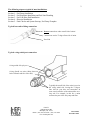
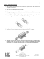
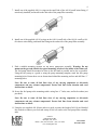
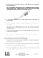
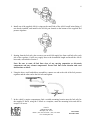
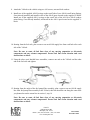
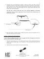
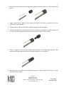
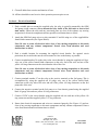
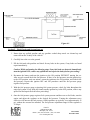
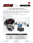
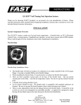
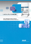
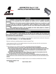
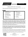
1
INSTRUCTIONS
#307500 and #307501 FAST™ Fuel System Kits
Thank you for choosing FAST™ products; we are proud to be your manufacturer of choice. Please
read this instruction sheet carefully before beginning the installation.
Kit Contents:
1 ea
1 ea
1 ea
1 ea
1 ea
2 ea
2 ea
5 ea
1 ea
6 ea
1 ea
3 ea
3 ea
fuel pump wiring kit
3ft length of 10 ga. Black wire
25ft length of 10 ga. Red wire
30 amp circuit breaker
30 amp automotive relay
blue female blade connector
yellow female blade connector
yellow #10 stud ring connector
yellow 3/8” stud ring connector
tie-wraps
AN-06 cutoff union
AN-10 cutoff union
AN-10 cutoff to AN-08 union
1 ea
1 ea
1 ea
1 ea
1 ea
2 ea
2 ea
1 ea
1 ea
12 ea
1 ea
8 ea
Pump
Filter 100 Micron SS
Filter 10 Micron Paper
Fuel Pressure Regulator
Y-block Assembly
AN-08 cutoff union
AN-08 o-ring
AN-10 cutoff to AN-08 union
AN-10 o-ring
tie-wraps
AN-06 o-ring
AN-10 o-ring
Caution: Installation of this product requires detailed knowledge of automotive systems and
repair procedures. We recommend that this installation be carried out by a qualified automotive
technician. Installation of this product requires handling of gasoline. Ensure you are working in
a well ventilated area with an approved fire extinguisher nearby. Extinguish all open flames,
prohibit smoking and eliminate all sources of ignition in the area of the vehicle before proceeding
with the installation. When installing this product, wear eye goggles and other safety apparel as
needed to protect yourself from debris and sprayed gasoline.
Warning: The fuel system is under pressure. Do not open the fuel system until the pressure has
been relieved. Refer to the appropriate vehicle service manual for the procedure and precautions
for relieving the fuel system pressure. FAST™ fuel system components are not legal for sale or
use on emission controlled motor vehicles. The included FAST™ fuel pump is not compatible
with alcohol based fuels or fuel additives!
This kit assumes you have a sumped fuel tank or fuel cell with accommodations for an AN-10 supply
line and an AN-06 return line. Fuel tank pickups will not work properly with FAST™ fuel systems and
will be detrimental to your fuel systems life. If your fuel tank is not sumped, we recommend having
your fuel tank sumped by a qualified professional. No fuel rails are provided with this kit, your fuel
rails must have accommodations to accept AN-08 hose ends in order to install this kit properly.
FAST™
3400 Democrat Rd.
Memphis, TN 38118
Phone: (901) 260-3278 Fax: (901) 375-3408
www.fuelairspark.com
Part #30161
Revised 8/14/07
2
The following steps are typical of most installations:
Section 1 – Fuel Pump Installation
Section 2 – Fuel Regulator Installation and Fuel Line Plumbing
Section 3 – Fuel Line Hose End Installation
Section 4 – Electrical Installation
Section 5 – Final Checks and System Start-up, Fuel Pump Template
Typical hose end to fitting connection:
Do not connect hose end to cutoff side of union!
Connect hose end to 37-degree flare side of union.
Hose End
Typical o-ring sealed port connection:
O-ring sealed AN style port
O-ring (Install on union fitting between
back of threads and face of hex nut.)
Typically the cutoff side of the union is used as
the o-ring sealed side, leaving the 37-degree
flare side for your hose end connection. In
some cases both sides of the union utilize an oring seal. For example, in this kit a union
connects the port of the fuel pump and filter.
FAST™
3400 Democrat Rd.
Memphis, TN 38118
Phone: (901) 260-3278 Fax: (901) 375-3408
www.fuelairspark.com
Part #30161
Revised 8/14/07
3
Section 1 - Fuel Pump Installation:
1. Once the engine has been allowed to cool, disconnect the negative battery cable and relieve the
fuel system of all pressure.
2. Raise the vehicle and support it with jack stands.
3. Referring to the appropriate vehicle service manual for instructions, drain, disconnect any
electrical and fuel component connections.
4. In the kit, find two AN-10 cutoff union fittings and four of the AN-10 o-rings. Install each of
the four o-rings on each end of the two AN-10 cutoff union fittings.
5. Install each of the two fittings into each end of the provided FAST™ fuel pump.
6. Noting the appropriate flow directions, install the provided fuel filter. If you get the two filters
mixed up, the fuel pump inlet side filter will have a 100 micron stainless steel filter element
inside, where as the fuel pump outlet filter will have a 10 micron paper filter element inside.
FAST™
3400 Democrat Rd.
Memphis, TN 38118
Phone: (901) 260-3278 Fax: (901) 375-3408
www.fuelairspark.com
Part #30161
Revised 8/14/07
4
7. Install one of the supplied AN-10 o-rings on the cutoff side of the AN-10 cutoff union fitting, if
not already installed, and install on the inlet side of the pump/filter assembly.
8. Install one of the supplied AN-10 o-rings on the AN-10 cutoff side of the AN-10 cutoff to AN08 reducer union fitting, and install the fitting on the outlet side of the pump/filter assembly.
9. Find a suitable mounting location for the above pump/filter assembly. Warning: Do not
mount on the gas tank shield; the typical mounting location is the inside of the frame rail.
The fuel pump should be mounted as close to the fuel tank as possible and as low as possible.
Using the fuel pump as a guide or using the pump mounting template, mark the four pump
mounting holes. Ensure there are no obstructions behind the mounting surface and drill four ¼”
mounting holes.
Note: Be sure to route all fuel lines clear of any moving suspension or drivetrain
components and any exhaust components! Protect fuel lines from abrasion and road
obstructions or debris.
10. Secure the fuel pump to the mounting surface using four ¼” bolts, nuts, and lock washers (not
provided).
Note: Be sure to route all fuel lines clear of any moving suspension or drivetrain
components and any exhaust components! Protect fuel lines from abrasion and road
obstructions or debris.
11. Using the two supplied AN-10 hose ends as a guide, measure the length of AN-10 steel braided
line needed to connect your fuel tank sump or fuel cell outlet to the fuel pump/filter assembly
inlet.
FAST™
3400 Democrat Rd.
Memphis, TN 38118
Phone: (901) 260-3278 Fax: (901) 375-3408
www.fuelairspark.com
Part #30161
Revised 8/14/07
5
12. Connect one end to the outlet of the fuel tank sump and the other end to the fuel pump/filter
assembly inlet and tighten.
Note: It is recommended that a fuel shut off valve be installed between the fuel tank outlet
and the fuel pump & filter assembly inlet, these valves are available from most popular
racing fitting manufactures; Aeroquip, Earl’s, Goodridge, Russell, etc.
13. In vehicles engine compartment, locate a suitable mounting location for the supplied fuel
pressure regulator.
14. Starting from the determined regulator mounting location in the engine compartment, plan a
route to run an AN-06 return line back to the fuel tank or fuel cell return port and measure the
required length.
Note: Be sure to route all fuel lines clear of any moving suspension or drivetrain
components and any exhaust components! Protect fuel lines from abrasion and road
obstructions or debris.
15. Thread one end of the AN-06 return line onto the AN-06 return line accommodations of your
fuel tank or fuel cell and tighten.
16. Make any line or electrical adjustments necessary to clear the vehicles exhaust, suspension, and
drivetrain components.
Section 2 – Fuel Regulator Installation and Fuel Line Plumbing
1. In the vehicle’s engine compartment, mount the supplied fuel pressure regulator in the location
established in step 1 – 15. Using the supplied mounting bracket as a template, mark the bracket
mounting holes and drill to accept a #10 screw.
2. With the bracket attached to the regulator, mount the bracket and regulator to the vehicle using
two #10 screws, nuts and lock washers (not provided).
3. Install two of the supplied AN-10 o-rings on the cutoff side of two AN-10 cutoff to AN-08
reducer union fittings, if not already installed, and install in each of the AN-10 ports located on
the sides of the supplied fuel pressure regulator.
FAST™
3400 Democrat Rd.
Memphis, TN 38118
Phone: (901) 260-3278 Fax: (901) 375-3408
www.fuelairspark.com
Part #30161
Revised 8/14/07
6
4. Install one of the supplied AN-06 o-rings on the cutoff side of the AN-06 cutoff union fitting, if
not already installed, and install in the AN-06 port located on the bottom of the supplied fuel
pressure regulator.
5. Starting from the fuel rails, plan a route to run an AN-08 supply line from each fuel rail to each
side of the regulator. Cut the two supply lines to the determined length and install the AN-08
hose ends, as detailed in Section 3.
Note: Be sure to route all fuel lines clear of any moving suspension or drivetrain
components and any exhaust components! Protect fuel lines from abrasion and road
obstructions or debris.
6. Using the above steel braided hose assemblies, connect one end to the side of the fuel pressure
regulator and the other end to the fuel rails and tighten.
7. In the vehicle’s engine compartment, find a suitable mounting location near the fuel rails for
the supplied Y-block, using the Y-block as a template, mark the mounting holes and drill to
accept a #10 screw.
FAST™
3400 Democrat Rd.
Memphis, TN 38118
Phone: (901) 260-3278 Fax: (901) 375-3408
www.fuelairspark.com
Part #30161
Revised 8/14/07
7
8. Attach the Y-block to the vehicle using two #10 screws, nuts and lock washers.
9. Install two of the supplied AN-08 o-rings on the cutoff side of two AN-08 cutoff union fittings,
if not already installed, and install in each of the AN-08 ports located on the supplied Y-Block.
Install one of the supplied AN-10 o-rings on the cutoff side of the AN-10 to AN-08 reducer
union fitting, if not already installed, and install in the AN-10 port located on the supplied Yblock.
10. Starting from the fuel rails, plan a route to run an AN-08 supply line from each fuel rail to each
side of the Y-block.
Note: Be sure to route all fuel lines clear of any moving suspension or drivetrain
components and any exhaust components! Protect fuel lines from abrasion and road
obstructions or debris.
11. Using the above steel braided hose assemblies, connect one end to the Y-block and the other
end to the fuel rails and tighten.
12. Starting from the outlet of the fuel pump/filter assembly; plan a route to run an AN-08 supply
line from fuel pump/filter assembly to the Y-block, this line should be run along the same route
you planned to run the return line in section 1, step 16.
Note: Be sure to route all fuel lines clear of any moving suspension or drivetrain
components and any exhaust components! Protect fuel lines from abrasion and road
obstructions or debris.
FAST™
3400 Democrat Rd.
Memphis, TN 38118
Phone: (901) 260-3278 Fax: (901) 375-3408
www.fuelairspark.com
Part #30161
Revised 8/14/07
8
13. Using the above steel braided hose assembly, connect one end to the outlet of the fuel
pump/filter assembly. Keeping both the supply line and return line from the fuel tank together,
secure both lines to the vehicle along the predetermined route using the supplied tie-wraps.
Once both lines are secure, connect the supply line to the Y-block and the return line to the
bottom of the regulator and tighten.
Note: Be sure to route all fuel lines clear of any moving suspension or drivetrain
components and any exhaust components! Protect fuel lines from abrasion and road
obstructions or debris.
14. Once the regulator is installed, attach a suitable fuel pressure gauge (not supplied) to the 1/8
NPT port on the fuel pressure regulator.
Section 3 - Fuel Line Hose End Installation
Caution: When assembling this product, wear eye goggles and other safety apparel as needed to
protect yourself from debris and sharp edges.
1. Wrap hose with masking tape at the desired cutoff length. Cut hose through masking tape
squarely to desired length using a cut-off machine or a fine tooth hacksaw and remove the
masking tape.
2. Unthread the hose socket from the rest of the hose end fitting.
FAST™
3400 Democrat Rd.
Memphis, TN 38118
Phone: (901) 260-3278 Fax: (901) 375-3408
www.fuelairspark.com
Part #30161
Revised 8/14/07
9
3. Insert hose in the socket with a twisting and pushing motion until the hose is fully seated in the
socket.
4. Using a grease pencil, marker or tape; mark the location of the hose in relation to the hose
socket that you just installed.
5. Using a light oil, lubricate the inside of the hose and hose end mating parts.
6. Carefully thread the hose end onto the hose socket, making sure that the hose does not push out
of socket, by observing the mark you placed on the hose in step 4 of this section.
7. Using a properly sized wrench, complete threading the two components together (The
maximum allowable gap between the two fitting components is .030 inches).
8. Inspect the hose for push out by comparing the mark you made on the hose in step 3-4 to the
hose end socket location.
FAST™
3400 Democrat Rd.
Memphis, TN 38118
Phone: (901) 260-3278 Fax: (901) 375-3408
www.fuelairspark.com
Part #30161
Revised 8/14/07
10
9. Clean all debris from exterior and interior of hose.
10. All lines should be tested to twice their operation pressure prior to use.
Section 4 - Electrical Installation
1. Find a suitable place to mount the supplied relay, the relay is typically mounted by the OEM
fuel pump wiring connector (Never mount the relay inside of the fuel tank or next to fuel
tank vents!). Ensure the relay and any associated parts are clear of the exhaust, any moving
suspension or drivetrain components and any possible road obstructions or debris.
2. Attach the OEM fuel pump wires to relay terminals 85 and 86 using two of the supplied blue
female blade connectors (See Figure Below).
Note: Be sure to route all electrical wires clear of any moving suspension or drivetrain
components, and any exhaust components! Protect wires from abrasion and road
obstructions or debris.
3. Find a suitable location for mounting the supplied circuit breaker. For optimal circuit
protection, the circuit breaker needs to be mounted as close to the battery as possible.
4. Connect terminal number 30 on the relay to the circuit breaker by using the supplied red 10 ga.
wire, one of the yellow female blade connectors on the relay end of the wire and one of the
yellow #10 ring connectors on the circuit breaker side of the wire.
Note: Be sure to route all electrical wires clear of any moving suspension or drivetrain
components and any exhaust components! Protect wires from abrasion and road
obstructions or debris.
5. Connect terminal number 87 on the relay to the positive terminal on the fuel pump. This is
accomplished by using the supplied red 10 gauge wire, one of the yellow female blade
connectors on the relay side of the wire and one of the yellow #10 ring connectors on the fuel
pump side of the wire.
6. Connect the negative terminal on the fuel pump to a clean chassis ground using the supplied
black 10 gauge wire and two yellow #10 ring connectors.
7. Connect 12VDC to the circuit breaker using the supplied red wire and one of the yellow #10
ring connectors and the supplied yellow 3/8” ring connector.
8. Ensure that electrical components and wires are connected properly (See Figure 4-1) and are
clear of any moving suspension or drivetrain components and any exhaust components! Protect
wires from abrasion and road obstructions or debris.
FAST™
3400 Democrat Rd.
Memphis, TN 38118
Phone: (901) 260-3278 Fax: (901) 375-3408
www.fuelairspark.com
Part #30161
Revised 8/14/07
11
Figure 4-1
Section 5 – Final Checks and System Start-up
1. Ensure that any spilled gasoline and any gasoline soaked shop towels are cleaned up and
removed from the vicinity of the vehicle!
2. Carefully lower the car to the ground.
3. Fill the fuel tank with gasoline and check for any leaks in the system, if any leaks are found
repair immediately.
Caution: While performing the following steps, if any fuel leaks are detected, immediately
turn the ignition OFF, remove any spilled fuel and repair the leak(s) before proceeding!
4. Reconnect the battery and turn the ignition to the ON position WITHOUT starting the car.
After several seconds check the fuel pressure. If there is no fuel pressure, turn the ignition key
to the OFF position, wait one minute, return the ignition to the ON position, and recheck the
fuel pressure. Repeat this ignition OFF and ON procedure until the fuel pressure gauge
registers fuel pressure.
5. With the fuel pressure gauge registering fuel system pressure, check for leaks throughout the
entire fuel system! If any leaks are found, turn the ignition key to the OFF position, remove any
spilled fuel and repair the leak before proceeding!
6. Once the fuel pressure gauge registers fuel system pressure and there are no fuel leaks, start the
engine and adjust the regulator to the desired fuel pressure. Turning the adjustment screw
clockwise will increase the fuel pressure. OEM regulators are typically set at approximately 43
psi, without the vacuum line attached. The fuel pressure adjustment range for this regulator is
35-80 psi.
FAST™
3400 Democrat Rd.
Memphis, TN 38118
Phone: (901) 260-3278 Fax: (901) 375-3408
www.fuelairspark.com
Part #30161
Revised 8/14/07
12
7. Once the desired fuel pressure is achieved, tighten the regulator adjustment jam nut & attach
vacuum line.
8. Test drive the car to ensure proper operation and re-check the fuel system for leaks. If any
leaks are found, immediately discontinue use of the vehicle and repair the leak(s)!
Limited Warranty
FAST, Inc. warrants that all of its products are free from defects in material and workmanship for a
period of 1 year from the date of purchase. This limited warranty shall cover the original purchaser.
FAST, Inc.’s obligation under this warranty is limited to the repair or replacement of its product. To
make a warranty claim, the part must be returned within 1 year of purchase to the address listed below,
freight prepaid. Items covered under warranty will be returned to you freight collect.
It is the responsibility of the installer to ensure that all of the components are correct before
installation. We assume no liability for any errors made in tolerances, component selection, or
installation.
There is absolutely no warranty on the following:
• Any parts used in racing applications.
• Any product that has been physically altered, improperly installed or maintained.
• Any product used in improper applications, abused, or not used in conjunction with the
proper parts.
There are no implied warranties of merchantability or fitness for a particular purpose. There are
no warranties, which extend beyond the description of the face hereof. FAST, Inc. will not be
responsible for incidental and consequential damages, property damage or personal injury damages to
the extent permitted by law. Where required by law, implied warranties or merchantability and fitness
are limited to a term of 1 year from the date of original purchase. This warranty gives you specific
legal rights and you may also have other legal rights, which vary from state to state.
FAST™
3400 Democrat Rd.
Memphis, TN 38118
Phone: (901) 260-3278 Fax: (901) 375-3408
www.fuelairspark.com
Part #30161
Revised 8/14/07