1
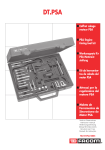
VS125 DIESEL & PETROL ENGINE SETTING/LOCKING & TIMING A D J U S T M E N T K I T - F O R C I T R O E N , P E U G E O T, R E N A U LT. STANDARD PARTS LIST VS125/C1 INJ. PUMP LOCKING PIN 1 2 VS125/C2 INJ. PUMP LOCKING PIN 3 VS125/C3 BALANCE SHAFT LOCKING PINS (PAIR) VS125/C4 INJ. PUMP LOCKING PIN 4 5 VS125/C5 CAMSHAFT LOCKING PIN 6 VS125/C6 FLYWHEEL TDC LOCKING PIN VS125/C7 FLYWHEEL TDC LOCKING PIN 7 8 VS125/C8 FLYWHEEL TDC LOCKING PIN 9 VS125/M8 LOCKING BOLTS (SET OF 3) 10 VS125/P1 CRANK/CAM LOCKING PIN 11 VS125/P2 CAMSHAFT LOCKING PINS (PAIR) CAMSHAFT LOCKING PIN 12 VS125/P3 13 VS125/P4 CRANK/CAM LOCKING PIN 14 VS125/P5 CAMSHAFT LOCKING PINS (PAIR) CRANK/CAM LOCKING PIN 15 VS125/P6 16 VS125/P7 CRANK. LOCKING PIN 17 VS125/P8 SHORT FLYWHEEL TDC LOCKING PIN 18 VS125/R1 CRANK. TDC LOCKING PIN CRANK. TDC LOCKING PIN 19 VS125/R2 20 VS125/R3 INJ. PUMP LOCKING PIN 21 VS125/R4 CRANK. LOCKING PIN 22 VS125/T1 RETAINING PIN (ROLLER) 23 VS125/T2 RETAINING PIN 24 VS125/T3 ADJUSTING BOLT 25 VS125/T4 TENSIONER TOOL (DYN. ROLLER) 26 VS1251 TENSIONER ADJUSTER 27 VS1252 TENSIONER ADJUSTER 28 VS1253 TENSIONER ADJUSTER 29 VS1254 TENSIONER TOOL 30 VS1250 SPROCKET MULTI-LOCK 31 VS1256 CAMSHAFT SETTING TOOL 32 VS1257 CRANK. TDC LOCKING PIN 33 VS1255 RAM ADJUSTING TOOL 34 VS1258 RAM NUT SOCKET 35 VS1259 PUMP TIMING ADAPTOR 36 VS125/1 EPIC TIMING PIN VS125/84 CASE & INSERT 1. INTRODUCTION & APPLICATION 1.1. INTRODUCTION 1.2. APPLICATION 1.3. USE PRODUCT WITH THE FOLLOWING TOOLS A comprehensive kit of setting/locking and adjustment tools covering engine timing and timing belt renewal on a very wide range of French diesel and petrol engines, including the latest direct injection and twin cams. The kit includes the unique Sprocket MULTI-LOCK Timing Device for use on Renault engines where timing position retention on camshafts and/or inj. pump is achieved by locking in to the teeth of the sprockets. In addition a full range of locking pins is provided including difficult access pins, plus a range of tensioner adjusting tools required for the specific belt tensioning applications called for on these engines. Also included are tools required for the Renault RAM injection timing and PSA EPIC electronic pump. Engine Setting/Locking and Tensioner Adjustment Tools for: Citroen, Peugeot, Renault Diesel and Petrol engines, and these engines fitted in Fiat/Iveco, Vauxhall, Rover, Volvo, LDV, Chrysler, Mitsubishi, FSO, Tata. Fuel injection Pump Timing Adjustment Tools for Renault RAM timing system and PSA EPIC injection pumps. See chapter 2 for model application. Flywheel Holding Tools (for belt change/crank pulley removal) . . . . . . . . . . . . .VS1283, VS1284, VS1285, VS1286, VS1287. See Application Charts for specific Citroen, Peugeot, Renault model application details. VS125 - 0869 - (1) - 010799 2. FULL APPLICATION CHARTS VS125 - 0869 - (1) - 010799 2. APPLICATION DETAILS CONTINUED VS125 - 0869 - (1) - 010799 s p p 7 3 3 3 3 3 p 2. APPLICATION DETAILS CONTINUED 3. SAFETY INSTRUCTIONS WARNING! Ensure all health and safety, local authority, and general workshop practice regulations are strictly adhered to when using tools. DO NOT use tools if damaged. Maintain the tool in good and clean condition for best and safest performance. If required ensure the vehicle to be worked on is adequately supported with axle stands, ramps and chocks. Wear approved eye protection. A full range of personal safety equipment is available from your Sealey dealer. Wear suitable clothing to avoid snagging. Do not wear jewellery and tie back long hair. Account for all tools, locking bolts, pins and parts being used and do not leave them in or near the engine. WARNING! Locking Pins must NOT be used to hold crankshaft whilst releasing or tightening the pulley bolt. Locking Pins are for retention of timing position only. Use an appropriate Flywheel Holding Tool. p WARNING! Remove locking pins from components in accordance with instructions, failure to do so will damage the engine, and pins. s IMPORTANT: Always refer to the vehicle manufacturers service instructions, or proprietary manual to establish the current procedure and data. s These instructions for use are provided as a guide only . 4. RENAULT INSTRUCTIONS FOR USE p WARNING! Ensure you have read and understood chapter 3 safety instructions before commencing. p 4.1. ENGINE SETTING/LOCKING TOOLS (Also see Twin Cam engine tools) DIESEL CAMSHAFT/INJECTION PUMP SPROCKET LOCKING 4.1.1. VS1250 Sprocket MULTI-LOCK Timing Device. VS1250 is designed to Lock twin camshafts, cam and/or injection pump sprockets on their timing marks to ensure the engine timing position is retained during timing belt removal/renewal. The VS1250 is uniquely adjustable in size between sprockets to provide a parallel fit or additionally, lateral/off-set positioning. It locates into the sprocket teeth giving a firm and secure lock. Once fitted securely into the teeth the MULTI-LOCK is clamped in final position using the two special ratcheting lock handles. Their ratchet mechanism allows tightening in the often restricted area around the sprockets as well as providing the strong lever action required for firm locking. Dependant upon application, the VS1250 Sprocket MULTI-LOCK is used complete as a combined left and right hand plate between two sprockets, or is disassembled and the plates used singly. When using a single plate it fits into the teeth of the sprocket and bolts onto the engine to lock the inj, pump sprocket.......Continued: VS125 - 0869 - (1) - 010799 s m On most Renault diesel engines the injection pump sprocket can be held on its timing mark by locking VS1250 onto the sprocket teeth. On F8M (1.6D) and J8S (2.1D/TD) engines the complete tool is used and timing positions are retained by locking into both the camshaft and injection pump sprockets (fig 1). m m m m For F8Q, F9Q (1.9D/TD), G8T(2.2D/TD) diesels a single plate only is used, being positioned in the inj pump sprocket teeth and bolted to the engine in the place provided to secure the timing position (fig 2). When using a single plate it can also be used to hold the injection pump sprocket firmly in place to release and tighten the pump/sprocket nut for timing/removal of the injection pump. For F8M & J8S engines - Use complete MULTI-LOCK VS1250. For F8Q/F9Q & G8T engines - Use single plate. NOTE: Engine types are fitted over a number of models. For engine references to vehicle model, refer to Renault applications chart. fig 1 fig 2 MULTI-LOCK Ratchet Lock Handles 4.1.2. VS125/R1 & VS125/R2 Crankshaft TDC Locking Pins 1 2 s m m m m Used on many Renault diesel and petrol engines, these pins enter datum holes in engine casing and locate into crankshaft to lock engine at TDC. Rotate the engine in the normal direction of rotation and align all timing marks ensuring No 1 cylinder is at TDC. Remove plug and insert locking pin to engage into the crankshaft datum hole. IMPORTANT Move crankshaft backward & forward slightly to ensure pin is inserted correctly For F8M, F8Q, F9Q, J8S diesel. D7F, F1/2/3. J5/7 petrol, and F7P/F7R Twin cams Use VS125/R1 For G8T 2.2 diesel engines . . . . . . . . . . . . . . . . . . . . . . . . . . . . . . . . . . . . . . . . . . . .Use VS125/R2 4.1.3. VS125/R3 & VS125/R4 Locking Pins. These Locking Pins are used as a pair to lock the crankshaft and injection pump on the Renault S8U/S9U diesel engines. The pins enter through holes in sprockets into datum holes on the engine. Ensure all timing marks are aligned and pin R4 will locate through and lock crankshaft pulley. Pin R3 will lock the injection pump sprocket. NOTE: If crank pulley does not have a hole, insert pin in the flywheel. m m s s For S8U/S9U 2.5 diesel engines......Use VS125/R3 & VS125/R4. IMPORTANT: Locking Pins must NOT be used to hold crankshaft whilst releasing or tightening the pulley bolt. Locking Pins are for retention of timing position only. Use an appropriate Flywheel Holding Tool. VS1284 4.1.4. FLYWHEEL HOLDING TOOLS (Optional Tools - not in kit). m m It is often necessary to remove the crankshaft pulley when replacing the timing belt. The pulley bolt has a high torque loading and the engine must be locked safely with the correct Flywheel Holding Tool when releasing/tightening the bolt. Use VS1283, VS1284, VS1285. Holding Tools, and for model/engine coverage, see Renault applications chart and separate instruction sheets. 4.2. RENAULT TENSIONER ADJUSTMENT TOOLS. VS125/T3, VS1251, VS1254 TENSIONER ADJUSTERS. VS1283 VS1285 fig 3 4.2.1. VS125/T3 Adjuster. Is required on petrol and diesel applications to allow tension to be applied to tensioner/belt. It is screwed into the threaded hole in rear upper timing cover to push the tensioner and apply tension to the belt (fig 3). m m For F8M, F8Q 1.6/1.9 diesel, and F1/2/3/ petrol/F7P/F7R Twin Cams . . . .Use VS125/T3. VS125 - 0869 - (1) - 010799 p m fig 4 4.2.2. VS1251 Tensioner Adjuster. m m The VS1251 turns the belt tensioner to apply correct tension. This specialised wrench locates into two holes on tensioner in Renault petrol engines and variant of J8S and S8U diesel engines (fig 4). For D7F, E5/E7, J7, K7M petrol, and J8S.760, S8U.8144 diesel engines . .Use VS1251. 4.2.3. VS1254 Tensioning Tool. 1 2 3 4 m m 4.3. Is used to apply tension to timing belt during the final belt tensioning procedure on D7F 1.2 petrol engines. Once initial tensioning procedure is completed, slacken tensioner nut and turn tensioner ant-clockwise using VS1251 until the two holes are in a horizontal position, and re-tighten nut. Rotate engine twice by hand in normal direction and return to TDC again ensuring that all timing positions align. Check TDC by inserting the Pin VS125/R1. p WARNING! DO NOT LEAVE PIN IN PLACE AFTER CHECKING TDC, REMOVE IT! p Fit Adaptor from VS1254 to crank sprocket and apply anti-clockwise torque, according to the vehicle manufacturers specification applying tension between crank and water pump sprockets (fig 5). This allows belt play to be eliminated. Check belt tension is correct. If not, adjust position of tensioner and repeat final tensioning procedure. NOTE: Rotate engine at lease twice each time tensioner position is changed. For final tensioning procedure on D7F petrol engines . . . .Use VS1254. fig 5 RENAULT TWIN CAM ENGINE TIMING TOOLS 4.3.1. VS1250 Multi-Lock Timing Device. 1.8/2.0 16v Twin Cams. m m In addition to diesel engine applications, the unique VS1250 Sprocket MULTI-LOCK is also used to Lock twin camshaft engine sprockets in their timed positions during timing belt replacement. On these Renault 1.8 and 2.0 16v (eg F7P/F7R) engines, the timing marks are aligned and VS1250 Multi-Lock is placed between the cam sprockets, expanded to engage into the teeth of both sprockets and tightened firmly in position to retain their timing positions. These engines also use VS125/R1 Crank TDC Lock Pin and VS125/T3 Tensioner Adjuster. For F7P/F7R Twin Cam engines . . . . . . . .Use VS1250 Multi-Lock + VS125/R1 & VS125/T3 VS1256 Camshaft Setting Tool. VS1257 Crankshaft TDC Locking Pin. VS125/T2 Tensioner Retaining Pin. 2.0 16v/2.5 20v Twin Cams. The Renault N7Q/N7U Twin Cam engines require both VS1256 Cam Setting Tool and VS1257 Crankshaft TDC Locking Pin for timing belt renewal applications. As the timing belt tensioner is removed and compressed during the application, VS125/T2 Retaining Pin is also necessary. 1. To remove the auxiliary belt use optional tool VS12501 to turn and lock the auxiliary belt tensioner. 2. Follow the service manual instructions to remove auxiliary belt tensioner, crankshaft pulley and cam position sensor/plug to expose rear of both camshafts. 3. Turn engine until groves in camshafts align as fig 6.1. Bolt on the two alignment arms of VS1256 Setting Tool and then turn crankshaft until arms meet as fig 6.2. Fit datum plate and bolt fig 6.3. 4. Fit VS1257 Crankshaft TDC Lock Pin through engine casing into the crankshaft. 5. Remove tensioner plunger and depress and retain with VS125/T2. 6. Remove timing belt. 7. Ensure setting tool and crank pin are in position. Slacken cam sprocket bolts whilst counter-holding with Holding Wrench (e.g. VS169) and position bolts in centre of sprocket slots. 8. Fit new belt. 9. Re-fit tension plunger and remove Pin VS125/T2. 10. Tighten cam sprocket bolts, whilst counter holding with Holding Wrench. 11. Remove setting tool and crank pin. 12. Turn engine almost two revolutions and refit VS1256 as before and turn crank until arms meet. 13. Check that Crank Pin VS1257 can be inserted and that all timing marks align. 14. Check that timing belt it to specified tension. Remove all tools and re-assemble engine. m m For N7Q/N7U Twin Cam Engines . . . . . . . . . . . . . . .Use VS1256, VS1257, VS125/T2. + Optional Tool VS1250 and Holding Wrench VS169. Sprocket MULTI-LOCK 4.3.2. fig 6.1. fig 6.2. fig 6.3. VS125 - 0869 - (1) - 010799 m p 4.4. RENAULT INJECTION PUMP TIMING ADJUSTMENT TOOLS . RAM (Reglage Angulaire Micrometrique) Adjustable Injection Pump Timing Sprocket VS1255 Timing Adjustment Tool and VS1258 Sprocket Nut Socket. fig 7 4.4.1. Checking Timing. Check injection pump timing with the appropriate Sealey Pump Timing Tool. m Bosch VE Rotary Pump VS107 or VS108. m CAV/Rotodiesel Pump VS110. m Combined Bosch/CAV Kit VS1131. See the instruction sheets of pump timing tools for installing and using the tools for checking pump timing. 4.4.2. Adjusting Timing. m m On later Renault F8Q/F9Q 1.9 diesel engines, the centre flange of the injection pump sprocket is adjustable and is used to adjust pump timing-RAM sprocket. VS1250 MULTI-LOCK and VS125/R1 Crankshaft Pin are used to secure engine timing position. VS1255 Adjustment Tool locates into the three holes in the sprocket centre flange for turning to adjust timing position. VS1258 Nut Socket slackens the RAM sprocket centre hub and flange (Left-hand thread) allowing the flange to turn. The engine is at TDC and the pump timing tool dial gauge shows the pump timing requires adjustment. Remove VS125/R1 Pin from the crankshaft. Turn engine to after TDC to achieve zero reading on the dial gauge. Preload dial gauge 1mm, and zero the gauge. Fit single plate from VS1250 MULTI-LOCK to lock into teeth of injection pump sprocket, and bolt/secure to engine (fig 7). Use VS1258 Nut Socket to slacken the sprocket centre nut and flange (Left-hand thread). Flange must turn freely (fig 8). Insert VS1255 into the three holes in flange and turn clockwise until its pins fully engage (fig 9). Remove the VS1250 plate which is locking the sprocket. Rotate engine twice and return to TDC. Insert VS125/R1 Pin. Ensure tool VS1255 is fully engaged and turn the centre flange anti-clockwise until the DTI gauge reads the correct timing value plus pre-load, per manufacturers specification for Bosch pumps or per figure given on load lever of CAV/Rotodiesel pumps. WARNING! If correct timing value is exceeded, it is essential to turn tool VS1255 back clockwise to 0.7mm below required value and then turn anti-clockwise again to correct value. This procedure also applies if the initial reading, when checking timing was higher than correct timing value. This action ensures no play in adjustment. Remove VS125/R1 Crankshaft Pin and re-fit VS1250 plate to lock sprocket. Using VS1258 re-tighten hub nut to 90Nm (left-hand thread). Remove all locking tools, rotate engine twice returning to TDC position and check pump timing again. For RAM Adjustable Timing Sprocket on F8Q/F9Q diesel engines . . .use VS1255, & VS1258. m m Required on some later Bosch VE Rotary Injection Pumps with changed service port thread size eg on F9Q engines. Used with VS107 or VS108 Pump Timing Tools. For Bosch VE Pumps on F9Q engines . . . . . . . . . . . . . . . .Use VS1259, with VS107 or VS108. 1. 2. 3. 4. 5. 6. 7. 8. 9. p p 10. 11. fig 8 fig 9 VS1259 4.4.3. VS1259 Injection Pump Timing Adaptor. 5. CITROEN & PEUGEOT INSTRUCTIONS FOR USE p WARNING! Ensure you have read and understood chapter 3 safety instructions before commencing. p 5.1. ENGINE SETTING/LOCKING TOOLS (Also see Twin Cam engine tools) 5.1.1. VS125/C6, C7, C8, P8 Flywheel TDC Locking Pins (Difficult Access Pins). 1. 2. m m m m m m m m This series of 4 shaped locking pins are designed to provide access to the Flywheel datum hole enabling the engine to be locked at TDC. Insert the locking pin through the access drilling to the casing and turn the engine by hand until the locking pin engages the hole in the flywheel. Access to the datum hole is often restricted by a component i.e. starter motor etc., the specific pin shapes are therefore essential to overcome difficult access (fig 10). NOTE: Similar PSA models do not necessarily use the same shaped pin as it is dependant upon components and systems fitted in the engine compartment. For For For For fig 10 XUD9AU, 9TF, XUD11, DJ/DK . . . . . . . . . . .Use VS125/C6. Early XUD7/9 . . . . . . . . . . . . . . . . . . . . . . . .Use VS125/C7 XUD7, 9A, 9TE, 9BTF, 11BTE . . . . . . . . . . .Use VS125/C8 TUD3/5 diesel and TU1/3/5/9 petrol . . . . . .Use VS125/P8 NOTE: Engine types are fitted over a number of models. For engine references to vehicle model, refer to Citroen/Peugeot Application Charts. VS125 - 0869 - (1) - 010799 p m 5.1.2. VS125/C1, C2, C3, C4, C5, M8, P1, P3, P4, P6, P7. Locking Pins-Camshaft, Injection Pump, Crankshaft, Balance Shafts. Citroen/Peugeot engines have access holes through pulleys/sprockets and fixed datum holes on the engine to allow the camshaft, injection pump and crank to be locked in their timed positions by use of a correctly sized locking pins. NOTE: To ensure accuracy of the timing position and access to the datum hole, it is essential to use the correct pins to suit each application. These pins are used in combinations of sizes according to the engine/model. For the full range of engines/models covered by each Pin combination, refer to Citroen/Peugeot Application Charts. p p WARNING! Locking pins must NOT be used to hold the crankshaft whilst releasing or tightening the pulley bolt. Locking Pins are for retention of timing position only. Use appropriate Flywheel Holding Tool VS1283, VS1286, VS1287. 5.2. 5.2.1. 5.2.2. 5.2.3. m m m m m m m m 5.3. CITROEN/PEUGEOT TENSIONER ADJUSTMENT TOOLS VS125/T1 & T4 Retaining tools. VS1252 & VS1253 Tensioner Adjusters. VS125/T1 Retaining Pin Is required when removing/replacing the timing belt on DJ5TED Di engines. It is necessary to compress the automatic roller tensioner and lock it using VS125/T1 Retaining Pin. fig 11 VS125/T4 Tensioner Tool (Dynamic Roller). VS125/T4 is essential for use on the Auxiliary Belt tensioner, when air conditioning/power steering is installed (fig 11). VS1252 and VS1253. Specialised wrenches for adjusting timing belt tensioner on Citroen/Peugeot diesel and petrol engines. VS1252 provides access onto the square drive on belt tensioner on XUD11/DK/DJ engines (fig 12). VS1253 carries out the similar function on TUD3, TUD5 diesel and TU1/2/3/9 and TU5J4 petrol engines. On early TU1/2/3/9 engines (-94), VS1253 can also be used with an appropriate weight to established timing belt tension. fig 12 For DJ5TED direct inj. engine . . . . . . . . . . . . . . . . . . . .Use VS125/T1 For XUD9/XUD11 engines (Aux, Belt Dyn, Roller) . . . . .Use VS125/T4 For XUD11/DK/DJ engines . . . . . . . . . . . . . . . . . . . . . . .Use VS1252 For TUD3/5 diesel & TU1/2/3/5/9 & TU5J4 petrol . . . . . .Use VS1253 CITROEN/PEUGEOT TWIN CAM ENGINE TIMING TOOLS VS125/P2, P3, P4 & P5, Locking Pins There are a number of Citroen/Peugeot 16v twin cam engines and all use locking pins to retain the engine timing position during belt renewal. These pins enter through access holes in each of the camshaft sprockets into fixed datum holes behind. A locking pin is also used to lock the flywheel at TDC. VS125/P2 and P5 are pairs of camshaft lock pins for 1.8. and 2.0 Twin Cams. VS125/P3 and P4 are individual pins used together for the cams on the 1.6 16v engine. Follow the vehicle manufacturers instructions precisely when working on these engines. Specific procedures must be followed in correct order. Later engines cam sprockets have slotted bolt holes to allow movement as part of assembly/tensioning procedure. m For XU9J4(D6C)/XU10J4(RFY) 2.0 16v . . . . . . . . . . .Use VS125/P2 (Pair) & VS125/P4 for Crank. m m For TU5J4/LE 1.6 16v . . . . . . . . . . . . . . . . . . . . . . . . . .Use VS125/P3 & P4 & VS125/P8 for Flywheel. m m For XU7JP4/XU10J4 (RFV/R6E) 1.8/2.0 16v . . . . . . .Use VS125/P5 (Pair) & VS125/P4 for Crank. m 5.4. CITROEN/PEUGEOT INJECTION PUMP TIMING ADJUSTMENT TOOLS EPIC Injection Pump (Electronic Programmed Injection). VS125/1 Timing Pin 1. 2. 3. 4. 5. m m This injection pump is found on XUD11BTE engines and is statically timed by use of VS125/1 Timing Pin. Lock flywheel at TDC using Locking Pin VS125/C6 or VS125/C8. Loosen any bolt/pipes etc which will prevent the pump being turned. Turn the pump to fully retard position and remove the timing plug. Insert VS125/1 Timing Pin and turn the pump in advance direction at the same time as pushing in the timing pin until it engages into the slot within the pump (enters further in ). Tighten all the fixings of the pump and remove both timing and flywheel pins. Refit plug to specified torque after checking seal is in place. Tighten all pipes and bleed system. For Epic inj, Pump/XUD11BTE engine . . . . . . .Use VS125/1 & VS125/C6 or C8. NOTE: It is our policy to continually improve products and as such we reserve the right to alter data, specifications and component parts without prior notice. IMPORTANT: No liability is accepted for incorrect use of product. WARRANTY: Guarantee is 12 months from purchase date, proof of which will be required for any claim. INFORMATION: Call us for a copy of our latest catalogue on 01284 757525 and leave your full name and address including your postcode. Sole UK Distributor Sealey Group, Bury St. Edmunds, Suffolk. 01284 757500 01284 703534 E-mail: [email protected] VS125 - 0869 - (1) - 010799