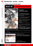
1
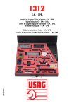
VS100B DIESEL ENGINE SETTING/LOCKING & FUEL INJECTION PUMP TIMING KIT. For: CAR & VAN DIESEL ENGINES. PARTS LIST 1. VS115/01 2. VS117/01 3 VS117/02 4 VS1079/01 5 VS1079/02 6 VS1079/03 7 VS1079/04 8 VS107/3 9 VS108/3 10 AK9634M 11 VS125/C7 12 VS125/P8 13 VS125/M8 14 VS103/1 15 VS101/1 16 VS114B/04 17 VS114B/01 18 VS114B/02 19 VS114B/03 20 VS101/2 21 VS101/3 22 VS103/2 23 VS101/4 24 VS101/5 25 VS101/6 26 VS101/7 27 VS110/1 28 VS110/2 29 VS110/3 30 VS110/4 31 VS106/5 32 VS1259 - VS100/84 1. 1.1. Camshaft Setting Plate Flywheel TDC Setting Tool Locking Pin Timing Adaptor (short) Extension Adaptor M12 Thread Adaptor Thumbscrew Indicator Pin-short Indicator Pin - Long Dial Test Indicator (DTI) Flywheel Locking Pin Flywheel Locking Pin (short) M8 Locking Bolts (3) M6 Locking Bolts (2) Camshaft Setting Plate Thumbscrew Camshaft Setting Plate Shoulder Screws (2) DTI Foot Crankshaft TDC Pin Locking Pins - Ø6.0mm (2) Locking Pins - Ø6.6mm (2) Locking Pin - Ø9.5mm Locking Pin - Ø15.4mm Locking Pin - Ø8.25mm Locking Pin - Ø12.7mm Main Body Assembly Toggle Indicator Pin DTI Extension Thumbscrew Pump Timing Adaptor Case + Insert INTRODUCTION & APPLICATION INTRODUCTION Engine performance is dependent on ensuring correct engine timing.This is fixed by engine design, and is affected when parts are removed from the engine. Maintaining or re-establishing camshaft, injection pump, crankshaft timing is essential when removing the timing belt or injection pump. VS100B kit provides a comprehensive range of engine setting and locking tools to maintain the datums and adjust timing on the engine and fuel injection pumps. 1.2. APPLICATION 1.3. USE PRODUCT WITH THE FOLLOWING TOOLS 1.4. ASSOCIATED TOOLS & APPLICATIONS Engine Setting and Locking Tools for AUDI, CITROËN, FIAT, FORD, MAZDA, PEUGEOT, ROVER, SEAT, VAUXHALL/OPEL, VOLKSWAGEN and VOLVO and Fuel Injection Pump Timing Tools for BOSCH, DIESEL KIKI, NIPPONDENSO VE ROTARY and CAV/ROTODIESEL pumps (top entry). An application list is provided, by vehicle model for the setting/locking tools and by injection pump type for the timing tools. See Section 2. Camshaft Alignment/Locking Tool Assembly - Vauxhall/Opel . . . .VS1065 Flywheel Holding Tool - Citroën/Peugeot . . . . . . . . . . . . . . . . . . .VS1283 Flywheel Holding Tool - Vauxhall/Opel . . . . . . . . . . . . . . . . . . . . .VS1280 Flywheel Holding Tool - Rover . . . . . . . . . .VS1287 Cam/Inj. Pump Sprocket Holding Tool . . . .VS169 Engine Setting/Locking Kit - French Engines . . . . . . . . . . . . . . . . . . . . . . . . . .VS125 Camshaft Locking Plate - Vauxhall/Opel (pre 87) . . . . . . . . . . . . . . . . . . . . . . .VS105 Water Pump/Camshaft Belt Adjusters - Vauxhall/Opel . . . . . . . . . . . . . . . . . . .VS092, VS093 Piston Travel Adaptor - Early XUD Engines (pre 87) . . . . . . . . . . . . . . . . . . . .VS109 VS100B - 0869 - (1) - 010900 2. APPLICATION DETAILS 2.1.ENGINE SETTING/LOCKING VS100B - 0869 - (1) - 010900 p 2.2. 2.3. XUD PEUGEOT DIESEL ENGINE TIMING (Pre 87) VS109 Piston Travel Adaptor - associated tool, not included in kit. Early XUD engines require the injection pump timing to be set at a position before TDC. VS109 Piston Travel Adaptor is required to accurately determine the piston position on these engines, when setting the fuel pump timing. Associated tool, not included in VS100B kit. See VS109 data sheet for details. VS109 p 7 3 3 3 3 3 p 3. with DTI SAFETY INSTRUCTIONS WARNING! Ensure Health and Safety, local authority, and general workshop practice regulations are adhered to when using tools. DO NOT use tools if damaged. Maintain tools in good and clean condition for best and safest performance. If required, ensure the vehicle to be worked on is adequately supported with axle stands, ramps and chocks. Wear approved eye protection. A full range of personal safety equipment is available from your Sealey dealer. Wear suitable clothing to avoid snagging. Do not wear jewellery and tie back long hair. Account for all tools, locking bolts, pins and parts being used and do not leave them in or near the engine. WARNING! Incorrect or out of phase camshaft timing can result in contact between the valve head and the piston crown causing possible damage to the engine. Incorrect injection pump timing may cause excessive smoke emissions, poor starting and low power output. IMPORTANT: Always refer to the vehicle manufacturers service instructions, or proprietary manual to establish the current procedure and data. These instructions for use are provided as a guide only . 4. INSTRUCTIONS FOR USE THE VS100B ENGINE SETTING/LOCKING TOOLS p WARNING! Ensure you have read and understood Section 3 safety instructions before commencing. p 4.1. 4.2. VS125/C7, VS125/P8 AND VS117/02 FLYWHEEL TDC LOCKING PINS Multi vehicle use (see Application Details). These are designed to pin point and lock the engine at TDC by alignment of a datum hole in the flywheel with a datum hole in the engine. Position the locking pin in the access drilling behind the starter motor or wherever the manufacturer has provided the access point. Rotate the engine by hand until the locking pin engages with the flywheel timing hole, the engine is now locked in correct timing position. VS125/C7 VS125/P8 VS101/1, VS115/01 CAMSHAFT SETTING/LOCKING PLATES Multi vehicle use (see Application Details). Camshaft setting/locking plates are used to accurately align a datum slot, located in the end of the camshaft, with the top face of the camshaft housing to hold the camshaft at the TDC position. 1. Follow the service manual instructions to remove the camshaft cover and timing belt cover. 2. Turn engine in the normal direction of rotation until the camshaft setting/locking plate can be inserted into the machined slot in the end of the camshaft. VS101/1 3. When fitting VS101/1, feeler gauges of equal thickness can be inserted on either side of the plate until all free play has been eliminated. The camshaft is now locked in its timing position and service work can now be carried out. 4.3. VS101/3, VS101/4, VS101/5, VS101/6, VS101/7, VS103/2, LOCKING PINS Multi vehicle use (see Application Details). Locking pins are designed to pass through datum holes in timing belt pulleys into fixed timing holes on the engine. These can be used at the injection pump pulley, the camshaft sprocket or the flywheel. Follow the service manual instructions to remove the engine timing cover where necessary. 4.4. VS101/5 1. Insert the locking pin through the timing pulley or fixed timing hole. 2. Rotate the engine slowly in the normal direction of rotation until the point at which the pulley timing holes and the engine timing holes are aligned. The locking pins can now be engaged to lock the engine in the correct timing position. VS101/2 CRANKSHAFT TDC LOCATION PIN Ford (see Application Details). VS101/2 is designed to screw into the cylinder block and provide a stop for the crank to be positioned against in order to set the TDC position. 1. Turn engine in the normal direction of rotation until the timing mark on the injection pump sprocket lines up with the cast lug on the timing cover. 2. Remove the plug from the cylinder block access hole and screw in VS101/2 Location Pin. 3. Slowly turn the crankshaft clockwise until contact is made with the pin. No. 1 cylinder is now set at TDC on ignition stroke. VS101/2 VS100B - 0869 - (1) - 010900 4.5. VS125/M8 VS103/1 AND VS125/M8 LOCKING BOLTS Multi vehicle use (see Application Details). These are used as an alternative to locking pins for positioning the camshaft and injection pump sprockets in the TDC position. Follow service manual instructions to remove engine timing covers where necessary. 1. Set engine to the correct point of timing using the engine timing marks (refer to workshop manual). 2. Screw the locking bolts into position, the engine is now locked and the timing belt can be removed without disturbing the engine timing. IMPORTANT: Locking Pins must NOT be used to hold the crankshaft whilst releasing or tightening the pulley bolt. Locking pins are for retention of timing position only. Use appropriate Flywheel Holding Tool. 4.5.1. Flywheel Holding Tools Associated Tools - not in kit. It is often necessary to remove the crankshaft pulley when replacing the timing belt. The pulley bolt has a high torque loading and the engine must be locked safely with the correct flywheel Holding Tool when releasing/tightening the bolt. Use VS1283 (Citroen/Peugeot) and VS1280 (Vauxhall/Opel), VS1287 (Rover) Holding Tools for model engine coverage - see application chart. 4.6. VS1283 VS1280 VS117/01 FLYWHEEL TDC SETTING TOOL Vauxhall/Opel, 17DTL engine (-97). When removing/installing timing belt and establishing or checking correct timing position, the VS117/01 Setting Tool is used to determine the flywheel/crankshaft TDC position. It is attached to the flywheel housing and provides the pointer position on which to align the TDC mark. 4.7. VS117/01 VS106A CAMSHAFT SETTING TOOL Vauxhall/Opel (87-), 16DA/17D/17DR/17DTL VS106A is used with with Associated Tool VS1065 Camshaft Locking Tool Assembly. For Pre 87 models - Use VS105 Locking plate optional tool not included in kit. VS106A is used with Dial Test Indicator AK9634M. It includes VS114B/03 Foot which must be screwed into the dial test indicator plunger. 4.7.1. Checking Timing Ensure all timing marks align at crankshaft (or by using VS117/01 TDC Setting Tool or VS117/02 Locking Pin dependant upon engine/MY). and at injection pump. Carry out timing belt tensioning procedure as per manufacturers instructions. Belt tension must be correct. 1. Turn crankshaft in the normal engine direction of rotation to 90 degrees before TDC (No.1 cylinder). 2. Insert and fix Dial Test Indicator AK9634M into VS106A Setting Plate. IMPORTANT: DTI must be held securely by lightly pinching with Thumbscrew. 3. Unscrew plunger end off DTI gauge and screw in its place indicator Foot VS114B/03. Ensure foot threads fully up to its shoulder into the DTI. 4. Fix VS114B/01 Plate into the camshaft housing holes, by using the 2 x VS114B/02 Shoulder Screws, at No.1 cylinder inlet valve (over 2nd cam lobe from front). 5. Push plate to the right to rest against right stop position so that the DTI foot rests on the base circle of cam (fig.1). 6. Release thumbscrew and pre-load the indicator to NOT MORE THAN 0.5mm, and secure the TDI firmly in the Plate with thumbscrew. 7. Set DTI gauge to zero (datum point). Push plate to the left to rest against the left stop position so that the indicator rests over the cam lobe (fig.2). NOTE: The dial test indicator will now read below the datum point. 8. Turn crankshaft in normal engine direction to TDC ensuring all timing marks align. The cam lobe will rise (fig.3), and the DTI will return to the zero datum point and continue to the correct nominal value of: 0.55 +/- 0.03mm. If nominal value is not obtained, cam timing must be adjusted. fig. 1 4.7.2. fig. 2 fig. 3 fig. 4 Adjusting Timing 1. Ensure timing belt tension is correct. 2. Check that all timing marks must be aligned and engine at TDC. 3. Locate spanner on camshaft hexagon and restrain while loosening fastening bolt of camshaft sprocket, ensuring the position of the crankshaft and camshaft remain unchanged.. 5. Remove crankshaft vent hose and fit Camshaft Lock Tool VS1065 (associated tool - not in kit) over No.4 cylinder and secure with three M6 x 1.0 screws (fig.4). VS100B - 0869 - (1) - 010900 6. VS106A Plate Assembly remains pushed to the left in its left stop position with the dial test indicator resting on the cam lobe (fig 3). 7. Turn camshaft carefully, with spanner of VS1065 in the normal engine direction until the dial test indicator reads approx 0.80mm. 8. Screw in the adjusting bolt of VS1065 until it rests against the spanner, then fine adjust with the adjusting bolt to turn the camshaft in opposite direction of normal rotation until dial test indicator gives a reading of 0.60 - 0.64mm (fig 4). 9. Remove VS106A ensuring the DTI position with the plate is not altered. 10. Leave VS1065 in place to lock the camshaft position whilst fitting new fastening bolt to camshaft sprocket (never refit old bolt) and tighten to specified torque. 11. Remove VS1065. 12. Rotate crankshaft 2 times and return to alignment of all timing marks. Re-install VS106A Plate Assembly in its left stop position, DTI resting on cam lobe, to check that the correct timing normal value of 0.55+/- 0.03mm has been achieved. IMPORTANT: Check diesel fuel injection pump timing using appropriate VS1079 or VS110 Pump Timing Tool after belt replacement. 4.8. 4.9. VS105 VS105 CAMSHAFT LOCKING PLATE AND SCREWS 1.6D/1.7D Engines - Vauxhall Astra/Cavalier (pre 87). Optional tool, not included in kit. VS105 Locking Plate bolts onto the camshaft housing in place of the vacuum pump and carries a peg to locate in a hole at the end of the camshaft to lock it in the TDC position on pre 87 models. Follow the service manual instructions and correctly align the crankshaft and injection pump timing marks. 1. Remove the vacuum pump from the camshaft carrier, offer the tool in place of the vacuum pump. 2. If the tool locates with the peg entering the camshaft hole the valve timing is correct and the camshaft is locked in position. Secure in place with three locking screws provided. 3. If the tool will not align correctly refer to service manual instructions and correctly adjust the camshaft timing. 4.9.1. VS1079 FUEL INJECTION PUMP TIMING TOOLS SECTION Diesel Injection Pump Timing Tool - Bosch Rotary VE Pumps, M8/M10/M12 service ports. VS1079/01 Short Timing Adaptor VS1079/02 Extension Adaptor VS1079/03 M12 Thread Adaptor VS1079/04 Thumbscrew VS107/3 Indicator Pin-Short VS108/3 Indicator Pin-Long VS1259 M10 Thread Adaptor VS1079 is a Timing Adaptor Set which connects to the service port of Bosch VE Rotary Injection Pumps to set the pump static timing position. VS1079/01 Adaptor can be used as a short reach adaptor or extended by adding VS1079/02 according to access capability around the service port area. Its M8 thread screws directly into the service port or Adaptor VS1079/03 or VS1259 can be fitted to allow connection into M12 and M10 service ports, respectively. VS1079 is used with AK9634M Dial Test Indicator. 1. Locate service port, clean and remove the pump blanking plug. 2. Unscrew plunger end off the DTI gauge and screw in its place VS108/3 (long) or VS107/3 (short) Indicator Pin whichever is appropriate to the configuration of timing adaptor being used (short or extended). Ensure the adaptor indicator pin threads fully up to its shoulder into the DTI. 3. Insert the DTI into the timing adaptor and screw it into the service port of the pump. IMPORTANT: Ensure the timing tool indicator pin is in constant contact with the injection pump plunger by pre-loading the DTI with sufficient pre-load to cover the full travel of the pump plunger, plus 1mm. The pre-load is shown on the minor scale of the indicator gauge. Secure the DTI by clamping with VS1079/04 Thumbscrew. 4. Turn the engine against the normal direction of rotation until the dial indicator needle reaches its lowest reading. Re-adjust the indicator gauge to ensure it has at least 1mm. of pre-load and then zero the dial indicator gauge. 5. Turn the engine in the normal direction of rotation to the static timing point and compare the DTI reading against the manufacturers timing data, allowing for the pre-load. VS1079 VS1079/01 VS1079/01 & VS1079/02 VS1259 VS100B - 0869 - (1) - 010900 4.9.2. VS110 Diesel Injection Pump Timing Tool - CAV/Rotodiesel DPC Rotary Injection Pump, top entry. VS110 is used for static timing of CAV/Rotodiesel injection pumps after servicing operations which may have affected the timing e.g. removal of the timing belt or pump. A. Checking the Timing. 1. Set the engine to its normal static timing points. 2. Clean top of pump, remove cap from entry port, and insert Pin VS110/3 into hole (fig.5). 3. Unscrew plunger end of AK9634M Dial Test Indicator and screw in its place Indicator Foot VS110/4. Ensure the foot threads fully up to its shoulder into the DTI. 4. Locate and clamp body VS110/1 on pump spigot (fig 6). 5. Fit Dial Test Indicator AK9634M into Body VS110/1 so that it touches the toggle arm, with the other toggle arm touching the top of the indicator Pin VS110/3 (fig 6). Ensure there is a small pre-load on the indicator gauge. 6. Turn crankshaft to set engine opposite to its normal static timing position. Ensure the indicator pin is FULLY DOWN to its shoulder into the entry port. Re-adjust the dial test indicator in the VS110/1 Body so that the arms of the toggle touch the DTI and Indicator Pin and apply a pre-load of 1mm. on the indicator gauge. B 7. Zero dial test indicator gauge. i) Turn crankshaft slowly in the normal direction of rotation to the correct engine timing position, and, if called for in service instructions, insert appropriate flywheel locking tool and/or injection pump sprocket locking bolts. ii) Check that the amount of lift on the indicator gauge corresponds to the figure stamped on the load lever plate (fig. 7), or on side of pump allowing for the 1mm pre-load. Each pump is calibrated and marked during manufacture. Timing Adjustment. 1. Set the engine to its static timing position and, if called for in service instructions, fit flywheel locking pin, injection pump sprocket bolts and/or camshaft locking bolt. 2. Ensure injection pump is in the fully retarded position (tilted away from the engine). 3. Clean top of pump, remove cap from entry port (fig.5), and insert Pin VS110/3 into hole. 4. Unscrew plunger end of AK9634M Dial Test Indicator and screw in its place Indicator Foot VS110/4 Ensure the foot threads fully up to its shoulders into the DTI. 5. Locate and clamp body VS110/1 on pump spigot (fig.6). 6. Fit Dial Test Indicator AK9634M into Body VS110/1 so that it touches the toggle arm with the other toggle arm touching the top of the indicator Pin VS110/3 (fig 6). Ensure there is a small pre-load on the indicator gauge. 7. Remove flywheel locking pin and sprocket locking bolts (if previously fitted). 8. Turn crankshaft to set engine opposite to its normal static timing position. Ensure the indicator Pin is FULLY DOWN to its shoulder into the entry port. Re-adjust the dial test indicator in the VS110/1 Body so that the arms of the toggle touch the DTI and indicator pin and apply a pre-load of 1mm. on the indicator gauge. 9. Zero dial test indicator gauge. i) Turn crankshaft slowly in the normal direction to the correct engine timing position and, if called for in service instructions, insert appropriate flywheel locking tool and/or injection pump sprocket locking bolts. ii) Turn pump until dial test indicator reading corresponds to figure stamped on the load lever plate (fig 7), or on side of the pump, allowing for the 1mm. pre-load. 10. Tighten pump retaining nuts and support bracket bolt to specified torque. 11. Remove flywheel locking pin and pulley bolts (if previously fitted). 12. Turn crankshaft two complete turns in normal direction of rotation. 13. Refit appropriate locking pin/bolts. 14. DTI should indicate specified figure +/- 0.04mm. IMPORTANT: Remove all locking pins and bolts. fig. 7 fig. 6 fig. 5 NOTE: It is our policy to continually improve products and as such we reserve the right to alter data, specifications and component parts without prior notice. IMPORTANT: No liability is accepted for incorrect use of product. WARRANTY: Guarantee is 12 months from purchase date, proof of which will be required for any claim. INFORMATION: Call us for a copy of our latest catalogue on 01284 757525 and leave your full name and address including your postcode. Sole UK Distributor Sealey Group, Bury St. Edmunds, Suffolk. 01284 757500 01284 703534 E-mail: [email protected] VS100B - 0869 - (1) - 010900