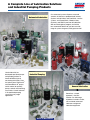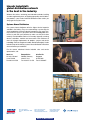
1
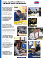
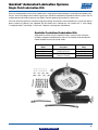
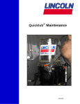
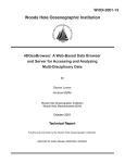
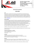
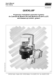
Quicklub®
Centralized & Automated Lubrication Systems
“I design Quicklub and other systems to satisfy each
customer’s unique requirements.”
Patrick Sändker, Application Engineer,
Lincoln Industrial Systems House, Walldorf Germany
Back to Main Menu
People, Capabilities and Systems to
Save Money and Increase Productivity
We’re the largest and most
successful company in our field
because we continually satisfy our
customers with the world’s best
lubrication and pumping systems.
For almost 90 years, companies
have relied on our technical and
quality leadership, our world-class
manufacturing and customer
service, and our vast network of
distributors and support facilities.
Industrial
Solutions
Worldwide Support
Lincoln Industrial develops new
products and systems at research
and development facilities in the
U.S., Germany and India that
provide global and regional
application solutions.
We have solutions for large
processing plants, automotive
manufacturing, pulp and paper
mills, and food and beverage
facilities. Virtually every industrial
professional involved in operations and
maintenance can benefit from Lincoln
Industrial systems.
Quality
Manufacturing
On the road or in the field, Lincoln Industrial
protects heavy equipment used in mining,
construction, agriculture and over-the-road
trucking. The world’s leading manufacturers
offer our systems as standard equipment or
factory options.
Lincoln Industrial builds precision
metal components, state-of-the-art
electronic controls, and the industry’s top-performing pump systems.
Our quality systems in the United
States and Germany are
ISO 9001 registered.
Customer Service
Research &
Development
BearingSaver®
With five technical support
centers on three continents, and
a network of system houses and
distributors supported by regional
sales and service offices, our
customers can always draw on
our worldwide resources.
To make sure your investment
results in significant savings,
Lincoln Industrial developed
a unique program called
BearingSaver.® You not only get
a complete audit of your facility,
you also receive an analysis of
your return on investment.
Mobile Equipment
Back to Main Menu
Quicklub® Lubrication Systems
Introduction to Quicklub®
The Lincoln Industrial Quicklub system is designed to provide a relatively simple and inexpensive method of centralizing
or automating the lubrication of machinery bearings.
Quicklub can be a simple, centralized system with lubricant supplied manually from a lever gun. Pre-assembled kits are
available to service up to 12 points from a single grease fitting. Custom kits can also be provided by our distributors to
cover virtually any quantity of points desired.
Quicklub can also be a fully automated system with lubricant supplied by our 12VDC and 24VDC electric or pneumatic
pumps. An automated lubrication system typically dispenses small measured amounts of lubricant at frequent intervals
while production machines are operating. The electric pumps incorporate an integrated timer for easy installation and
trouble-free operation.
Quicklub systems have proven to be the right solution for many industries and applications, eliminating costly, manual
point-by-point lubrication. Examples include:
• Packaging
• Lathes
• Beverage industry
• Textile
• Metal Working
• Wood Processing
• Plastic Processing
• Bakery
• Printing
• Punch presses
• Paper Converting
• Milling
• Material Handling Equipment
2
Back to Main Menu
Quicklub® Lubrication Systems
Introduction to Quicklub®
The heart of the Quicklub® system
More than a drilled manifold block, the valve incorporates a series of metering pistons which accurately dispense lubricant
from each outlet, overcoming back pressure of up to 1,000 psi. Visual monitoring is provided with an indicator pin, which
confirms a valve has completed a full cycle. Quicklub divider valves are available for grease or oil applications, and in
carbon steel and 303 stainless steel for corrosive environments.
Figure 1
Figure 2
Figure 3
Figure 4
The inlet passageway is connected to all piston chambers at all times with only one piston free to move at any time.
• With all pistons at the far right, lubricant from the inlet flows against the right end of piston A (fig. 1).
• Lubricant flow shifts piston A from right to left, dispensing lubricant through connecting passages to outlet 2.
Flow is then directed against the right side of piston B (fig. 2).
• Piston B shifts from right to left, dispensing lubricant through outlet 7. Lubricant flow is directed against the right side
of piston C (fig. 3).
• Piston C shifts from right to left, dispensing lubricant through outlet 5. Lubricant flow is directed against the right side
of piston D.
• Piston D shifts from right to left, dispensing through outlet 3. Piston D’s shift directs lubricant through a connecting
passage to the left side of piston A (fig. 4).
Lubricant flow against the left side of piston A begins the second half-cycle, which shifts pistons from left to right, dispensing lubricant through outlets 1,8,6 and 4 of the divider valve.
Figure 5
Crossporting a divider valve
7
Outputs from adjacent outlets may be combined by installing a closure plug in one or
more outlets. Lubricant from a plugged outlet is redirected to the next adjacent outlet
in descending numerical order. Outlets 1 and 2 must not be plugged since they have
no cross-port passage to the next adjacent outlet.
In figure 5, outlets 5 and 3 are cross-ported and directed through outlet 1. In this
example, outlet 1 will dispense three times as much lubricant as outlet 7. The tube
ferrules in outlets 1 and 7 block the cross-port passage so that lubricant flow is only
directed through outlets.
5
3
1
3
Back to Main Menu
Quicklub® Lubrication Systems
Divider Valves
SSV Divider Valves
The SSV Divider Valve is the “heart” of a manual or automated Quicklub system. Featuring from 6 to 18 outlets, the
SSV valve is available in carbon steel and 303 stainless steel for corrosive environments. Valves are available with cycle
indicator pins to provide visual indication of system operation.
Specifications:
Construction
Material
Carbon Steel
Stainless Steel
Max. Operating Pressure
psig / bar
Output/Cycle per Outlet
cu. in. / cc
4350 / 300
.012 / .2
Lubricant
Inlet
¹⁄₈" NPTF(F)
¹⁄₈" BSPP(F)*
Operating Temp.
min
max
-22˚F (-30˚C)
212˚F (100˚C)
Note: Lubricant outlet must use Lincoln Industrial Quicklub fittings. See Divider Valve Accessories section.
* 241650 stainless steel adapter available to convert inlet to ¹⁄₈" NPTF (F).
Model No.
Carbon Steel
619271211
619271221
619263962
619266462
619268441
619268452
619263982
619266482
619272921
303
Stainless Steel
619274721
619274741
619274761
619274781
Maximum
Number of
Outlets
6
8
10
12
18
Cycle
Indicator
Pin
No
Yes
No
Yes
No
Yes
No
Yes
Yes
Dimension A
in. / mm
2.36
60
2.95
75
3.54
90
4.14
105
6.50 / 165
Note:
You must use outlets 1 and 2 for each of the above referenced models to allow the system to operate properly
with the exception of Model 619272921, which requires utilization of outlets 17 and 18.
SSV Divider Valve Accessories
Part Number
249010
Description
Cycle switch for providing feedback monitoring for SSV systems
Note:
Cycle switch can only be used with SSV Series Quicklub valves that have indicator pins. Remove slotted plug from indicator
assembly on valve prior to installing switch.
4
Back to Main Menu
Quicklub® Lubrication Systems
Divider Valves
SSVM Divider Valves
The SSVM Divider Valve is smaller in overall size than the SSV series and provides smaller volume output per outlet.
Available with 6 to 12 outlets, the SSVM series valve is used primarily in oil system applications.
Specifications:
Construction
Material
Carbon Steel
Maximum
Operating Pressure
psig / bar
1450 / 100
Output/Cycle
per Outlet
cu. in. / cc
Lubricant
Inlet
min
.0037 / .06
¹⁄₈" NPTF(F)
-22˚F (-30˚C)
Operating Temp.
max
212˚F (100˚C)
Note:
Lubricant outlet must use Lincoln Industrial Quicklub fittings. See Divider Valve Accessories section.
Model No.
Carbon Steel
619267641
619267653
619266501
619266513
619268481
619268492
619266531
619266543
Maximum
Number of
Outlets
6
8
10
12
Cycle
Indicator
Pin
No
Yes
No
Yes
No
Yes
No
Yes
Dimension A
in. / mm
1.91 / 48.5
2.36 / 60
2.81 / 71.5
3.26 / 83
Note:
You must use outlets 1 and 2 in all systems.
5
Back to Main Menu
Quicklub® Lubrication Systems
Fittings, Adapters & Accessories
Zerk-Lock™ and Quicklinc® Make Connecting Fast
Installing lubrication systems can take a lot of time, especially when there’s not
much space to work with. Those problems are a thing of the past with Lincoln
Industrial’s unique Zerk-Lock and Quicklinc connectors and adapters. Great for
hard-to-reach places and those spots where there’s no room for a wrench,
Zerk-Lock and Quicklinc cut the time it takes to install line connections in half—
or more—when compared to screw-type connectors.
Quicklinc line connectors and adapters link metering valves and flexible lubrication
lines. Outlet adapters with check valves are used in automated systems, while models
without a check valve are used in manual systems—called single point kits—where a
divider valve connected to several lubrication points is fed with a grease gun.
The Quicklinc tube splicer union is a great way to fix a broken line without
replacing the whole line. Just clean the line ends, plug them into the connector
and the line’s repaired.
Quicklinc lube point connectors are ideal when fittings can be removed easily. All
three varieties—straight, 90-degree elbow and elbow swivel—connect much faster
than using a typical screw connector, which requires assembly of four components.
Zerk-Lock is Lincoln Industrial’s other great time-saving connector. When removing a
fitting is not practical, the Zerk-Lock grease fitting adapter is the answer. It connects
any 1/8-inch male tube adapter directly to a grease fitting. Even when a fitting is
self-tapered or pressed in, there’s no need to drill it out and tap new threads with
Zerk-Lock—a tremendous time saving.
Box Quantities:
Model No.
Description
252751
Valve outlet fitting with check for 1/4'' nylon tubing
252752
Valve outlet fitting without check for 1/4'' nylon tubing
252753
1/4'' tube x 1/8'' NPT male straight fitting
252754
1/4'' tube x 1/8'' NPT male 90° fitting
252755
1/4'' tube x 1/8'' NPT male 90° swivel fitting
252756
1/4'' tube x 1/4''- 28 male straight fitting
252757
1/4'' tube x 1/4''- 28 male 90° fitting
252758
1/4'' tube x 6 mm male 90° fitting
252759
1/4'' tube x 6 mm straight fitting
252760
1/4'' tube x 1/4'' tube splicer union
252761
1/8'' NPSL female Zerk-Lock grease fitting adapter
The models are economy packaged, 50 pieces per carton.
Quicklinc and Zerk-Lock are designed to work well together. It’s as simple as:
1. Install a Quicklinc
2. Place a Zerk-Lock
into the divider valve
onto the fitting
and insert the line
3. Seal and tighten
Zerk-Lock using
a hammer and
staking tool
4. Then thread a
Quicklinc completely
into the Zerk-Lock
6
Back to Main Menu
5. And plug the tube
into the Quicklinc
adapter
Quicklub® Lubrication Systems
Fittings, Adapters & Accessories
Standard Compression Fittings for Steel
or Nylon Tubing
Part No.
241290
241293
Description
¹⁄₄" tube x ¹⁄₈" NPT male straight fitting
¹⁄₄" tube x ¹⁄₈" NPT male 90° fitting
Quicklinc® Push-In Style Fittings for Nylon Tubing
Part No.
244047
244048
243699
244054
244055
244056
244057
244058
Description
¹⁄₄" tube x ¹⁄₈" NPT male straight fitting
¹⁄₄" tube x ¹⁄₈" NPT male 90° fitting
¹⁄₄" tube x ¹⁄₈" NPT male 90° swivel fitting
¹⁄₄" tube x ¹⁄₄ - 28 male straight fitting
¹⁄₄" tube x ¹⁄₄ - 28 male 90° fitting
¹⁄₄" tube x 6 mm male 90° fitting
¹⁄₄" tube x 6 mm straight fitting
¹⁄₄" tube x ¹⁄₄" tube splicer union
Divider Valve Outlet Adapters Without Check Valves
Quicklub® adapters without check valves are for use in manual systems where
lubricant is supplied from hand grease guns or pneumatic powered lever guns.
Quicklub® adapters with check valves are for use in all automated systems.
Divider Valve Outlet Adapters for ¹⁄₄" O.D. Steel or
Nylon Tubing Compression Style With Check Valve
Part No.
68462
402226021
504316063
404225812
Description
Ferrule ¹⁄₄"
Compression nut
Check valve body
Clamping ring
Divider Valve Outlet Adapters for ¹⁄₄" O.D. Steel or
Nylon Tubing Compression Style Without Check Valve
Model
404202364
404236681
404225812
Description
Comp. Nut
Comp. Nut
Ferrule
Divider Valve Outlet Adapters for ¹⁄₄" O.D. Nylon
Tubing Quicklinc® Push-In Style
Part No.
244883
244884
Description
Valve outlet fitting with check
Valve outlet fitting without check
Divider Valve Outlet Adapters for ¹⁄₈" I.D. Hose
Part No.
404225812
239857
239959
Description
Clamping ring
Valve outlet adapter with check
Valve outlet adapter without check
7
Back to Main Menu
Quicklub® Automated Lubrication Systems
Fittings, Adapters & Accessories
Divider Valve Mounting Accessories
Part No.
246416
Description
Valve mounting bracket
51304
247023
¹⁄₄" nylon locknut for valve mounting
Grade 8, ¹⁄₄" valve mounting bolt
239499
Template for divider valve mounting
(6,8, 10 and 12 outlet valves)
Template for 18 outlet (model 619272921) valve
241233
Divider Valve Outlet Closure Plugs & Gaskets
Part No.
209121582
Description
Valve outlet closure plug gasket
303174992
Valve outlet closure plug
Supply and Feed Line Hose
Min.
Burst
Lube
Working
Pressure
10,000
psig
690 bar
4000
psig
276 bar
Part No.
241285
241286
241287
241288
252717
Nominal Size
I.D.
O.D.
Minimum
Bending
Radius
¹⁄₈"
⁵⁄₁₆"
3¹⁄₂"
Construction
Nylon Tube
Dacron Braid
Polyurethane Cover
Description
2 ft. (.61m) coil grease filled
26 ft. (7.92m) coil grease filled
35 ft. (10.66m) coil grease filled
40 ft. (12.19m) coil grease filled
200 ft (60.96m) coil non-grease filled
Hose Ends for ¹⁄₈" I.D. Hose
Part No.
Description
241289
¹⁄₈" NPT swedge on hose stud (requires swedging tool)
¹⁄₈" NPT field installable hose coupling
246002
(swedging tool not required)
Feed Line Nylon Tubing
O.D.
Inches
Wall Thickness
In. / mm
¹⁄₄"
.050 / 1.27
Part No.
242025
242050
62357
247022
Working Pressure Minimum Bending
in / mm
psig
bar
625
42.5
.875 / 22.2
Description
25 ft. (7.62m) coil grease filled
50 ft. (15.24m) coil grease filled
100 ft. (30.48m) coil non-grease filled
500 ft. (152.40m) coil non-grease filled
8
Back to Main Menu
Quicklub® Automated Lubrication Systems
Fittings, Adapters & Accessories
Pipe Thread Adapters
Model
No. Style
Style 1
Style 3
Style 2
13154
13155
14054
20024
20026
20028
20029
A
B
⁷⁄₈
3
1
3
3
1
2
1
1
⁷⁄₈
⁷⁄₈
¹³⁄₁₆
1
1
C
D
E
³⁄₈ ¹⁄₂ sq. ¹⁄₈ NPSM
³⁄₈ ¹⁄₂ sq. ¹⁄₈ NPSM
⁷⁄₁₆ ¹⁄₂ sq. ¹⁄₈ NPSM
⁵⁄₁₆ ¹⁄₂ hex ¹⁄₄-28 Taper
⁵⁄₁₆ ¹⁄₂ sq. ¹⁄₄-28 Taper
¹⁵⁄₃₂ ¹⁄₂ sq.
¹⁄₈ PTF
¹⁵⁄₃₂ ¹⁄₂ sq.
¹⁄₈ PTF
¹⁄₈ NPTF
90°
¹⁄₈ NPTF
¹⁄₈ NPSF
90°
45°
90°
F
G
¹⁄₄-28 UNF
¹⁄₈ NPTF ¹⁄₄-28 UNF
¹⁄₄-28 UNF
¹⁄₈ PTF
¹⁄₈ PTF
¹⁄₈ PTF
Metric Adapters
Model No.
Description
20042
20043
244201
6 mm male x ¹⁄₈" NPSF female straight
6 mm male x ¹⁄₈" NPSF female 90°
¹⁄₈" BSPT male x ¹⁄₈" NPT female thread
Zerk-Lock™ Grease Fitting Adapter
Connects any ¹⁄₈" NPTF male tube adapter directly to a standard grease fitting.
Aluminum, carbon steel construction; fluorocarbon elastomer seal.
Model No.
247340
Thread
¹⁄₈" NPSL Female
A
in.
.625
mm
15.9
Dimensions
B
C-Hex
in.
mm
in.
mm
.500
12.7
.500
12.7
Note:
Zerk-Lock, with a straight female thread, is designed to accept a tube connector with a
tapered male thread. This tapered to straight thread engagement is required for secure seal.
Grease Fittings
Part No.
Description
5010
¹⁄₄" - 28 taper threaded straight fitting
5045
¹⁄₈" NPT threaded straight leakproof fitting
5050
¹⁄₄" PTF special extra short straight fitting
5200
¹⁄₈" PTF special short 45° fitting
5300
¹⁄₈" PTF special short 65° fitting
5400
¹⁄₈" PTF special short 90° fitting
5410
¹⁄₄" - 28 taper threaded 90° fitting
5701
¹⁄₈" PTF special short straight buttonhead fitting
242125
Plastic grease fitting cap
9
Back to Main Menu
Quicklub® Lubrication Systems
Fittings, Adapters & Accessories
Swivels
Part No.
Description
91048
¹⁄₈" NPT male x ¹⁄₈" NPT female 90° swivel
91308
¹⁄₈" NPT male x ¹⁄₈" NPT female straight swivel
Adapter Unions and Locknuts
Part No.
Description
66649
¹⁄₈" NPT male x ¹⁄₈" NPT female swivel adapter union
51055
¹⁄₈" NPSM locknut utilized for remote ¹⁄₈" I.D. hose
bulkhead connections
Installation/Assembly Tools
Part No.
Description
241237
Plastic tube and hose cutter
241238
Swedging tool for field installation of Model 241289
241239
QL screwdriver
System Finishing Accessories
Part No.
Description
241110
Feed line bundling spiral wrap (10 ft. (3m) length)
241054
Nylon ties (100 count poly bag)
241055
Nylon ties (50 count poly bag)
10
Back to Main Menu
Quicklub® Lubrication Systems
Installation Components
Lubricant flows through supply lines between the pump and divider valves, then through feed lines between the divider
valves and the bearing. Tubing and/or pipe sizes are determined after considering both the length of the line and the
specific lubricant intended for use in the system.
Your Lincoln Industrial representative can assist you in the proper selection of supply and feed line material to optimize
your application.
Listed below is a simplified outline of the installation components offered. For a complete listing of products, please
refer to the Installation Components catalog.
TUBING
Hydraulic, Steel, Stainless Steel
and Nylon
Single and Multiple Tube
Clamps
Heavy Duty, Standard Duty,
Threaded Sleeve and Snap-On
Coupler Tube Fittings
Quicklinc™ Tubing Adapter
Zerk-Lock™ Grease Fitting
Adapters
Non-Metallic
PIPING
Seamless
Continuous Welded
Forged Fittings
Malleable Iron Fittings
316 Stainless Steel Pipe
and Fittings
Stainless Steel Fittings
Galvanized Pipe, Threaded Plug
and Fittings
ACCESSORIES
Supply, Feed and Bulk Feed
Line Hose
Air Hose
Kits for Hose Repair
Heavy-Duty Air Line Quick
Disconnects
AIR CONTROL
AND ACCESSORIES
Manual Shut-Off Valves
Pressure Gauges
Air Line Equipment Accessories:
Wall Mount Bracket, High
Capacity; Mounting Bracket
and Nut, Miniature; Pressure
Gauges
Lubricant Filters and Strainers
PIPE FITTINGS
AIRCARE™ AIR
PREPARATION SYSTEMS
Modular Air Line Filters,
Regulators and Lubricators
Integrated/Modular
Filter/Regulator with Gauge
Modular Air Line
Combination Units
High Capacity Air Line Filters,
Regulators and Lubricators
High Capacity Air Line
Combination Units
Miniature Air Line
Components—Air Line Filter,
Regulator and Lubricator
Miniature Air Line
Combination Units
Reducing Bushings
Nipples
Couplings
Reducing Couplings
Street Ells
Tees
Crosses
Adapter Unions
Elbows
Pipe Fitting Adapters
Supply Line Swivels
Feed Line Swivels
Anchor and Junction Blocks
Modular Air Line Equipment
Accessories:
Lockout Valve, Quick Clamp,
Quick Clamp Wall Mounting
Bracket, Porting Block, Quick
Mount Pipe Adaptors, Manifold
Block, Pressure Switch, Panel
Nut, Wall Mount Bracket,
Tamper Resistant Cover
& Seal Wire
11
Back to Main Menu
Quicklub® Lubrication Systems
Electric Grease Pumps—203 Series
Models 94124, 94224 and 94212
These industrial lube pumps are electrically operated and are used in progressive
type (Quicklub or Modular Lube) automated lubrication systems. The pump
consists of a nylon housing, electric gear motor, and a plastic reservoir with stirring paddle. One model incorporates a built-in timer, with the other two cycled by
independent timers or machine controls. The pump’s ability to develop high
operating pressures allows it to supply lubricant up to NLGI #2 grease in
most ambient temperatures.
Model:
Output/Min Per Element**:
Reservoir Capacity:
Lubricant Outlet:
Maximum System Operating Pressure:
Enclosure Rating:
Operating Temperature Range:
Reservoir Fill Method:
Pressure Relief Valve:
94124/94224/94212
.171 cu. in.
4 lb.
122 cu. in.
¹⁄₈" NPT (F)
3600 psig
IP54*
Min. -13°F
Max. 158°F
By grease fitting
4000 psi, +/- 250
2.8 cc
1.8 kg
2000 cc
248 bar
-25°C
70°C
276 bar, +/- 17
* Protected from water sprayed in all directions.
** Single 6mm element standard; to increase pump output, add one or two additional element(s) #600268762
and relief valve(s) #249567.
Internal Timer Setting
Model
Electrical
Number Requirements
94124
94224
24 VDC
2 amps
12 VDC
3.5 amps
94212
On Time
(2 min. increments)
Min
Max
2 min.
30 min.
Off Time
(1 hour increments)
Min
Max
1 hour
15 hours
Timer not included with Models 94224 and 94212.
Select external timer from System Controls section.
Model 249567 Pressure Relief Valve
Designed to protect supply lines in instances of high pressure caused by a blocked
component inlet or extremely cold temperatures. The valve assembly consists of a
pressure relief valve, a grease fitting for manual servicing of the system and an 1/8"
NPT female supply line connection.
Pump Elements
Model
No.
600268752
600268762
600268772
*600287501
Piston
Lubricant
Max. Operating Connection
Diameter
Output
Pressure
Thread
5 mm
.122 in3/min / 2 cm3/min
6 mm
.171 in3/min / 2.8 cm3/min
5000 psi
G 1/4"
350 bar
3
3
7 mm
.244 in /min / 4 cm /min
* Special hammer paste element for electric grease pumps to be used for applications on
hydraulic hammers.
Pump Reservoir Conversion Kits & Accessories
Part Number
544320221
544320231
638375491
246322
*241419
*241484
Description
4 liter conversion kit
8 liter conversion kit
Manual grease filler pump
Remote push button manual lube kit
12 VDC illuminated manual switch
24 VDC illuminated manual switch
* To be used with #246322 remote push button manual lube kit
12
Back to Main Menu
Quicklub® Automated Lubrication Systems
Electric Grease Pumps—QLS 301 Series
QLS 301
The newest automated Quicklub Lubrication System—the QLS 301—has it all.
It’s compact, rugged, easy to install and easy to use. It has a long list of
standard features and delivers maximum performance, all at an affordable price.
For those who thought the reduced downtime and improved safety of automated
lubrication were out of reach, and for those waiting for a cost-effective system
for their smaller machinery, the reliable QLS 301 is the answer. It’s automated
lubrication “made easy.”
Operating Voltage:
Operating Current:
Operating Temperature:
Number of Outlets:
Reservoir Capacity:
Protection:
Lubrication Cycle Time:
Number of Cycles:
Timer Memory:
Maximum Operating Pressure:
Output per Outlet & Cycle:
Lubricant:
Weight:
12 and 24 VDC
120 and 230 VAC, 50/60 Hz
12 VDC
1.0 A
24 VDC
1.5 A
120 VAC
1.0 A
230 VAC
0.5 A
-10° to 158°F
-25° to 70°C
6, 8, 12 or 18
61 in3
1.0 L
NEMA 4
20 min. to 100 hours
1 (with 6, 8 divider block
1, 2 or 3 cycles are possible)
Indefinite
3000 psig
205 bar
3
approx. 0.012 in
approx. 0.2 cm3
NLGI 2 grease
12.5 lbs.
5.7 kg
Available Models
Model
P301 31211151
P301 31411151
P301 42611111
P301 42811111
P301 61211151
P301 61411151
P301 62611111
P301 62811111
P301 91211151
P301 91411151
P301 92611111
P301 92811111
Valve
Type
SSV6
SSV6
SSV8
SSV8
SSV12
SSV12
SSV12
SSV12
SSV18
SSV18
SSV18
SSV18
Valve
Mount
Back
Back
Bottom
Bottom
Back
Back
Bottom
Bottom
Back
Back
Bottom
Bottom
Volt
Cable
12DC
24DC
120AC
120AC
12DC
24DC
120AC
230AC
12DC
24DC
120AC
230AC
30’ / 10m
30’ / 10m
none
none
30’ / 10m
30’ / 10m
none
none
30’ / 10m
30’ / 10m
none
none
Note: All models include low level and remote contacts.
Inch Accessory Size Kits
SSV 6/8 part number 550-36971-1
SSV 12 part number 550-36971-2
SSV 18 part number 550-36971-3
Note: Includes ¹⁄₄" O.D. tubing and appropriate Quicklinc and Zerk-Lock fittings.
13
Back to Main Menu
Quicklub® Automated Lubrication Systems
Air Operated (Single Stroke) Pumps
Model 604265381 Grease Pump
Includes sheet metal reservoir, spring-loaded follower and filler fitting for refilling of
reservoir with 81834 filler pump.
Model:
Lubricant:
Number of Outlets:
Ratio:
Output/Stroke/Outlet:
Reservoir Capacity:
Air Inlet:
Lube Outlet:
Maximum Lubricant Pressure:
Reservoir Level Indication:
Fill Method:
604265381
Grease
8
40:1
.018 cu. in.
.3 cc
3 lb.
1.5 liter
91 cu. in.
1500 cc
¹⁄₈" NPTF Female
See note #2
3675 psig
250 bar
Rod
Through grease fitting
Notes:
1. 3-way air valve required for pump operation.
2. Model 604265381 has integrated Divider Valve with cycle indicator pin and must use
Lincoln Industrial Quicklub Fittings. See Divider Valve section for part numbers.
3. One pump stroke will cycle the eight outlet progressive divider valve approximately 1.7 cycles.
Model 604272251 Oil Pump
Includes transparent reservoir.
Model:
Lubricant:
Number of Outlets:
Ratio:
Output/Stroke/Outlet:
Reservoir Capacity:
Air Inlet:
Lube Outlet:
Maximum Lubricant Pressure:
Reservoir Level Indication:
Fill Method:
604272251
Oil
1
40:1
.16 cu. in.
2.6 cc
3.8 pints
1.8 liter
110 cu. in.
1800 cc
¹⁄₈" NPTF Female
¹⁄₄" O.D. tube connection
4400 psig
300 bar
Visual through transparent reservoir
Fill cap and screen
Note:
1. 3-way air valve required for pump operation.
14
Back to Main Menu
Quicklub® Automated Lubrication Systems
System Controls
The controls listed on the following two pages are designed to control the amount of time the selected system pump is
on and the duration between lube events.
Model 84501 Program Timer—Solid State
Designed to control the lubrication cycle frequency of air operated single stroke
pumps. Timer turns pump on/off at programmed intervals via a 3-way air solenoid
valve (not included) installed in the air line to pump.
Off Time
(Cycle Time)
Min
Max
20 Sec.
24 Hrs.
On Time
(Pumping Time)
Min
Max
1 Min.
10 Sec.
24 Sec.
Built-In Program Options
3 Hr.
Program
Memory
Prelube
Function
Power
Approvals
Requirements
120/230 VAC
50/60 Hz
120 VAC, 5 Amps
UL, CSA 230 VAC, 1.5 Amps
Ambient Operating
Temperature Range
Enclosure
Rating
Dimensions-in./mm
Height Width Depth
NEMA #1
8¹⁄₄
210
6¹³⁄₁₆
173
Switch
Capacity
4¹⁵⁄₁₆
125
Minimum Maximum
0°F
-18°C
130°F
54°C
Note:
Refer to Technical Manual for a full explanation of available program options.
Model 84511 Economy Timer for
Single Stroke Pumps
Uses a timing motor, cam and Micro-Switch to turn pump off and on. NEMA 1
enclosure, UL and CSA listed. Switch capacity 10 amps non-inductive.
Off Time
(Cycle Time)
Min
Max
5 Min.
1 Hr.
On Time
(Pumping Time)
Min
Max
30 Sec.
90 Sec.
Power
Approvals
Requirements
Switch
Capacity
120 VAC, 60 Hz
10 Amps
UL, CSA
Note: Off-time selectable in 5 minute intervals.
Rating
NEMA 1
Enclosure
Dimensions - in. / mm
Height
Width
Depth
5 / 127
3¹⁄₄ / 82.5
3¹⁄₂ / 89
15
Back to Main Menu
Quicklub® Automated Lubrication Systems
System Controls
Model 84015 Timer—12-24V DC
Solid state timer for automated lubrication systems requiring DC power. Rugged
construction with liquid and dust-tight enclosure. Includes manual push button for
remote initiation of a lube cycle.
Off Time**
(Cycle Time)
Min.
2.5 Min.
Max.
Fixed On Time
(Pumping Time)
Power
Requirements
Switch
Capacity
75 Sec.
10-30 VDC
25 MA*
5 Amps
80 Min.
* Less load.
** Available selections are 2.5, 5, 10, 20, 40 or 80 minutes.
Rating
NEMA 12
Enclosure
Dimensions-in / mm
Height
Width
Depth
5¹⁄₄ / 133
3¹⁄₈ / 79
3 / 76
Ambient Operating Temperature Range
Minimum
Maximum
0°F / -18°C
131°F / 55°C
Electric Solenoid Operated Air Valves
Electrical Characteristics
Power
Inrush Holding
Air
Model Type
Requirements Current Current Inlet/
Amps Amps Outlet
350241
350242
3
Way
110 VAC, 50 Hz
120 VAC, 60 Hz
8.4 VA
220 VAC, 50 Hz
240 VAC, 60 Hz
8.4 VA
.11
Ambient
Temp.
Range
Max. Conduit
Press.
Conn.
psi / bar
.07
¹⁄₄"
0° - 140°F
NPTF(F) -18° - 60°C
.055
Cv
Factor
.035
16
Back to Main Menu
1.8
150
10.2
¹⁄₂"
NPS(F)
Quicklub® Automated Lubrication Systems
Single Point Lubrication Kits
These kits are designed to service up to 12 points from a single grease fitting utilizing our 12 point SSV series divider valve.
The kits, which are available with or without a grease gun, include all componentry required to install the system. Kits are
available primed with NLGI #2 grease or non-filled if a specific grade or type of grease is to be used.
These kits effectively replace the concept of using grease fittings mounted to a central manifold with a system that delivers
precise amounts of lubricant, fully monitored with the divider valve’s indicator pin. Kits include 100' ¹⁄₄" nylon tubing,
12 straight Quicklinc® tube fittings, 12 Zerk-Lock™ adapters, mounting clips and hardware.
Quicklub Centralized Lubrication Kits
Single point kits contain all items required to install a system on your machinery,
including a complete installation/service manual. The selection chart describes the
models available to meet your specific needs.
Model
87311
87312
87411
87412
Selection Chart
Description
Kit with single fitting for use with
portable grease gun.
Complete kit with grease gun for
permanent mounting.
Tubing
Non-filled
Pre-filled
Non-filled
Pre-filled
17
Back to Main Menu
Quicklub® Automated Lubrication Systems
Numerical Index
Part No.
Page No.
Part No.
Page No.
5010 . . . . . . . . . . . . . . . . . . . . . . . . . . . . . . . . . . . . . . 9
91308 . . . . . . . . . . . . . . . . . . . . . . . . . . . . . . . . . . . . 10
5045 . . . . . . . . . . . . . . . . . . . . . . . . . . . . . . . . . . . . . . 9
94124 . . . . . . . . . . . . . . . . . . . . . . . . . . . . . . . . . . . . 12
5050 . . . . . . . . . . . . . . . . . . . . . . . . . . . . . . . . . . . . . . 9
94212 . . . . . . . . . . . . . . . . . . . . . . . . . . . . . . . . . . . . 12
5200 . . . . . . . . . . . . . . . . . . . . . . . . . . . . . . . . . . . . . . 9
94224 . . . . . . . . . . . . . . . . . . . . . . . . . . . . . . . . . . . . 12
5300 . . . . . . . . . . . . . . . . . . . . . . . . . . . . . . . . . . . . . . 9
239499 . . . . . . . . . . . . . . . . . . . . . . . . . . . . . . . . . . . . 8
5400 . . . . . . . . . . . . . . . . . . . . . . . . . . . . . . . . . . . . . . 9
239857 . . . . . . . . . . . . . . . . . . . . . . . . . . . . . . . . . . . . 7
5410 . . . . . . . . . . . . . . . . . . . . . . . . . . . . . . . . . . . . . . 9
239959 . . . . . . . . . . . . . . . . . . . . . . . . . . . . . . . . . . . . 7
5701 . . . . . . . . . . . . . . . . . . . . . . . . . . . . . . . . . . . . . . 9
241054 . . . . . . . . . . . . . . . . . . . . . . . . . . . . . . . . . . . 10
13154 . . . . . . . . . . . . . . . . . . . . . . . . . . . . . . . . . . . . . 9
241055 . . . . . . . . . . . . . . . . . . . . . . . . . . . . . . . . . . . 10
13155 . . . . . . . . . . . . . . . . . . . . . . . . . . . . . . . . . . . . . 9
241110 . . . . . . . . . . . . . . . . . . . . . . . . . . . . . . . . . . . 10
14054 . . . . . . . . . . . . . . . . . . . . . . . . . . . . . . . . . . . . . 9
241233 . . . . . . . . . . . . . . . . . . . . . . . . . . . . . . . . . . . . 8
51304 . . . . . . . . . . . . . . . . . . . . . . . . . . . . . . . . . . . . . 8
241237 . . . . . . . . . . . . . . . . . . . . . . . . . . . . . . . . . . . 10
20024 . . . . . . . . . . . . . . . . . . . . . . . . . . . . . . . . . . . . . 9
241238 . . . . . . . . . . . . . . . . . . . . . . . . . . . . . . . . . . . 10
20026 . . . . . . . . . . . . . . . . . . . . . . . . . . . . . . . . . . . . . 9
241239 . . . . . . . . . . . . . . . . . . . . . . . . . . . . . . . . . . . 10
20028 . . . . . . . . . . . . . . . . . . . . . . . . . . . . . . . . . . . . . 9
241285 . . . . . . . . . . . . . . . . . . . . . . . . . . . . . . . . . . . . 8
20029 . . . . . . . . . . . . . . . . . . . . . . . . . . . . . . . . . . . . . 9
241286 . . . . . . . . . . . . . . . . . . . . . . . . . . . . . . . . . . . . 8
20042 . . . . . . . . . . . . . . . . . . . . . . . . . . . . . . . . . . . . . 9
241287 . . . . . . . . . . . . . . . . . . . . . . . . . . . . . . . . . . . . 8
20043 . . . . . . . . . . . . . . . . . . . . . . . . . . . . . . . . . . . . . 9
241288 . . . . . . . . . . . . . . . . . . . . . . . . . . . . . . . . . . . . 8
51055 . . . . . . . . . . . . . . . . . . . . . . . . . . . . . . . . . . . . 10
241289 . . . . . . . . . . . . . . . . . . . . . . . . . . . . . . . . . . . . 8
62357 . . . . . . . . . . . . . . . . . . . . . . . . . . . . . . . . . . . . . 8
241290 . . . . . . . . . . . . . . . . . . . . . . . . . . . . . . . . . . . . 7
66649 . . . . . . . . . . . . . . . . . . . . . . . . . . . . . . . . . . . . 10
241293 . . . . . . . . . . . . . . . . . . . . . . . . . . . . . . . . . . . . 7
68462 . . . . . . . . . . . . . . . . . . . . . . . . . . . . . . . . . . . . . 7
241419 . . . . . . . . . . . . . . . . . . . . . . . . . . . . . . . . . . . 12
84015 . . . . . . . . . . . . . . . . . . . . . . . . . . . . . . . . . . . . 16
241484 . . . . . . . . . . . . . . . . . . . . . . . . . . . . . . . . . . . 12
84501 . . . . . . . . . . . . . . . . . . . . . . . . . . . . . . . . . . . . 15
242025 . . . . . . . . . . . . . . . . . . . . . . . . . . . . . . . . . . . . 8
84511 . . . . . . . . . . . . . . . . . . . . . . . . . . . . . . . . . . . . 15
242050 . . . . . . . . . . . . . . . . . . . . . . . . . . . . . . . . . . . . 8
87311 . . . . . . . . . . . . . . . . . . . . . . . . . . . . . . . . . . . . 17
242125 . . . . . . . . . . . . . . . . . . . . . . . . . . . . . . . . . . . . 9
87312 . . . . . . . . . . . . . . . . . . . . . . . . . . . . . . . . . . . . 17
243699 . . . . . . . . . . . . . . . . . . . . . . . . . . . . . . . . . . . . 7
87411 . . . . . . . . . . . . . . . . . . . . . . . . . . . . . . . . . . . . 17
244047 . . . . . . . . . . . . . . . . . . . . . . . . . . . . . . . . . . . . 7
87412 . . . . . . . . . . . . . . . . . . . . . . . . . . . . . . . . . . . . 17
244048 . . . . . . . . . . . . . . . . . . . . . . . . . . . . . . . . . . . . 7
91048 . . . . . . . . . . . . . . . . . . . . . . . . . . . . . . . . . . . . 10
244054 . . . . . . . . . . . . . . . . . . . . . . . . . . . . . . . . . . . . 7
18
Back to Main Menu
Quicklub® Automated Lubrication Systems
Numerical Index
Part No.
Page No.
Part No.
Page No.
244055 . . . . . . . . . . . . . . . . . . . . . . . . . . . . . . . . . . . . 7
303174992 . . . . . . . . . . . . . . . . . . . . . . . . . . . . . . . . . 8
244056 . . . . . . . . . . . . . . . . . . . . . . . . . . . . . . . . . . . . 7
402226021 . . . . . . . . . . . . . . . . . . . . . . . . . . . . . . . . . 7
244057 . . . . . . . . . . . . . . . . . . . . . . . . . . . . . . . . . . . . 7
404202364 . . . . . . . . . . . . . . . . . . . . . . . . . . . . . . . . . 7
244058 . . . . . . . . . . . . . . . . . . . . . . . . . . . . . . . . . . . . 7
404225812 . . . . . . . . . . . . . . . . . . . . . . . . . . . . . . . . . 7
244201 . . . . . . . . . . . . . . . . . . . . . . . . . . . . . . . . . . . . 9
404236681 . . . . . . . . . . . . . . . . . . . . . . . . . . . . . . . . . 7
244883 . . . . . . . . . . . . . . . . . . . . . . . . . . . . . . . . . . . . 7
504316063 . . . . . . . . . . . . . . . . . . . . . . . . . . . . . . . . . 7
244884 . . . . . . . . . . . . . . . . . . . . . . . . . . . . . . . . . . . . 7
544320221 . . . . . . . . . . . . . . . . . . . . . . . . . . . . . . . . 12
246002 . . . . . . . . . . . . . . . . . . . . . . . . . . . . . . . . . . . . 8
544320231 . . . . . . . . . . . . . . . . . . . . . . . . . . . . . . . . 12
246322 . . . . . . . . . . . . . . . . . . . . . . . . . . . . . . . . . . . 12
550369711 . . . . . . . . . . . . . . . . . . . . . . . . . . . . . . . . 13
246416 . . . . . . . . . . . . . . . . . . . . . . . . . . . . . . . . . . . . 8
550369712 . . . . . . . . . . . . . . . . . . . . . . . . . . . . . . . . 13
247022 . . . . . . . . . . . . . . . . . . . . . . . . . . . . . . . . . . . . 8
550369713 . . . . . . . . . . . . . . . . . . . . . . . . . . . . . . . . 13
247023 . . . . . . . . . . . . . . . . . . . . . . . . . . . . . . . . . . . . 8
600268752 . . . . . . . . . . . . . . . . . . . . . . . . . . . . . . . . 12
247340 . . . . . . . . . . . . . . . . . . . . . . . . . . . . . . . . . . . . 9
600268762 . . . . . . . . . . . . . . . . . . . . . . . . . . . . . . . . 12
249010 . . . . . . . . . . . . . . . . . . . . . . . . . . . . . . . . . . . . 4
600268772 . . . . . . . . . . . . . . . . . . . . . . . . . . . . . . . . 12
249567 . . . . . . . . . . . . . . . . . . . . . . . . . . . . . . . . . . . 12
600287501 . . . . . . . . . . . . . . . . . . . . . . . . . . . . . . . . 12
252751 . . . . . . . . . . . . . . . . . . . . . . . . . . . . . . . . . . . . 6
604265381 . . . . . . . . . . . . . . . . . . . . . . . . . . . . . . . . 14
252717 . . . . . . . . . . . . . . . . . . . . . . . . . . . . . . . . . . . . 8
604272251 . . . . . . . . . . . . . . . . . . . . . . . . . . . . . . . . 14
252752 . . . . . . . . . . . . . . . . . . . . . . . . . . . . . . . . . . . . 6
619263962 . . . . . . . . . . . . . . . . . . . . . . . . . . . . . . . . . 4
252753 . . . . . . . . . . . . . . . . . . . . . . . . . . . . . . . . . . . . 6
619263982 . . . . . . . . . . . . . . . . . . . . . . . . . . . . . . . . . 4
252754 . . . . . . . . . . . . . . . . . . . . . . . . . . . . . . . . . . . . 6
619266462 . . . . . . . . . . . . . . . . . . . . . . . . . . . . . . . . . 4
252755 . . . . . . . . . . . . . . . . . . . . . . . . . . . . . . . . . . . . 6
619266482 . . . . . . . . . . . . . . . . . . . . . . . . . . . . . . . . . 4
252756 . . . . . . . . . . . . . . . . . . . . . . . . . . . . . . . . . . . . 6
619266501 . . . . . . . . . . . . . . . . . . . . . . . . . . . . . . . . . 5
252757 . . . . . . . . . . . . . . . . . . . . . . . . . . . . . . . . . . . . 6
619266513 . . . . . . . . . . . . . . . . . . . . . . . . . . . . . . . . . 5
252758 . . . . . . . . . . . . . . . . . . . . . . . . . . . . . . . . . . . . 6
619266531 . . . . . . . . . . . . . . . . . . . . . . . . . . . . . . . . . 5
252759 . . . . . . . . . . . . . . . . . . . . . . . . . . . . . . . . . . . . 6
619266543 . . . . . . . . . . . . . . . . . . . . . . . . . . . . . . . . . 5
252760 . . . . . . . . . . . . . . . . . . . . . . . . . . . . . . . . . . . . 6
619267641 . . . . . . . . . . . . . . . . . . . . . . . . . . . . . . . . . 5
252761 . . . . . . . . . . . . . . . . . . . . . . . . . . . . . . . . . . . . 6
619267653 . . . . . . . . . . . . . . . . . . . . . . . . . . . . . . . . . 5
350241 . . . . . . . . . . . . . . . . . . . . . . . . . . . . . . . . . . . 16
619268441 . . . . . . . . . . . . . . . . . . . . . . . . . . . . . . . . . 4
350242 . . . . . . . . . . . . . . . . . . . . . . . . . . . . . . . . . . . 16
619268452 . . . . . . . . . . . . . . . . . . . . . . . . . . . . . . . . . 4
209121582 . . . . . . . . . . . . . . . . . . . . . . . . . . . . . . . . . 8
619268481 . . . . . . . . . . . . . . . . . . . . . . . . . . . . . . . . . 5
19
Back to Main Menu
Quicklub® Automated Lubrication Systems
Numerical Index
Part No.
Page No.
619268492 . . . . . . . . . . . . . . . . . . . . . . . . . . . . . . . . . 5
619271211 . . . . . . . . . . . . . . . . . . . . . . . . . . . . . . . . . 4
619271221 . . . . . . . . . . . . . . . . . . . . . . . . . . . . . . . . . 4
619272921 . . . . . . . . . . . . . . . . . . . . . . . . . . . . . . . . . 4
619274721 . . . . . . . . . . . . . . . . . . . . . . . . . . . . . . . . . 4
619274741 . . . . . . . . . . . . . . . . . . . . . . . . . . . . . . . . . 4
619274761 . . . . . . . . . . . . . . . . . . . . . . . . . . . . . . . . . 4
619274781 . . . . . . . . . . . . . . . . . . . . . . . . . . . . . . . . . 4
638375491 . . . . . . . . . . . . . . . . . . . . . . . . . . . . . . . . 12
P301 31211151 . . . . . . . . . . . . . . . . . . . . . . . . . . . . . 13
P301 31411151 . . . . . . . . . . . . . . . . . . . . . . . . . . . . . 13
P301 42611111 . . . . . . . . . . . . . . . . . . . . . . . . . . . . . 13
P301 42811111 . . . . . . . . . . . . . . . . . . . . . . . . . . . . . 13
P301 61211151 . . . . . . . . . . . . . . . . . . . . . . . . . . . . . 13
P301 61411151 . . . . . . . . . . . . . . . . . . . . . . . . . . . . . 13
P301 62611111 . . . . . . . . . . . . . . . . . . . . . . . . . . . . . 13
P301 62811111 . . . . . . . . . . . . . . . . . . . . . . . . . . . . . 13
P301 91211151 . . . . . . . . . . . . . . . . . . . . . . . . . . . . . 13
P301 91411151 . . . . . . . . . . . . . . . . . . . . . . . . . . . . . 13
P301 92611111 . . . . . . . . . . . . . . . . . . . . . . . . . . . . . 13
P301 92811111 . . . . . . . . . . . . . . . . . . . . . . . . . . . . . 13
20
Back to Main Menu
A Complete Line of Lubrication Solutions
and Industrial Pumping Products
Automated Lubrication
Lincoln Industrial has
developed specialized pumps
and pumping stations to
handle the difficult job of
transferring thick fluids. From
the industry-best PileDriver III®
and PowerMaster III® pumps
and air motors to specialty
pumps, controls and mounting
accessories, Lincoln Industrial
is the preferred pumping
system for many tough
applications.
Our automated systems dispense measured
amounts of lubricant at predetermined intervals.
Systems include Helios® and Duo-Matic™ two-line
systems, and Centro-Matic®, Modular Lube®,
Quicklub® and ORSCO precision oil lubrication.
With our BearingSaver® program, we find the
best automated solution for you from our wide
range of systems for grease, fluid grease and oil.
Industrial Pumping
General Lubrication
Sometimes a simple
approach is the best
solution. Our wide range
of products includes smaller,
self-contained automated
lubricators and general
lubrication equipment.
Back to Main Menu
Lincoln Industrial’s
global distribution network
is the best in the industry.
Whatever the service—evaluating your lubrication methods, installing
a custom-engineered system, or supplying top-quality manual lubrication products—your Lincoln Industrial distributor makes certain you
always get the very best value.
Systems House Distributors
Our systems house distributors offer the highest level of expertise
available in the industry. They can custom design a system with the
exact combination of Lincoln Industrial components you need. Then,
they install the system in your plant with their knowledgeable technicians or work with your personnel to make sure the job is done
correctly. Each distributor stocks a full inventory of pumps, metering
devices, controllers, monitors and accessories. Each continues to
meet our stringent requirements for product, systems and service
knowledge. From Los Angeles to London, Boston to Bangkok, Lincoln
Industrial’s top-of-the-industry systems house distributors will be there
when and where you need them.
For the nearest authorized Lincoln Industrial sales and service
representative, call:
Americas:
St. Louis, Missouri
314-679-4200
Fax: 800-424-5359
Europe/Africa:
Walldorf, Germany
49-6227-33-0
Fax: 49-6227-33-259
One Lincoln Way
St. Louis, MO 63120-1578
USA
Asia/Pacific:
Singapore
65-5627960
Fax: 65-5629967
Phone 314-679-4200
Fax 314-679-4359
www.lincolnindustrial.com
Form 442833 (6/99)
© Copyright 1999
Printed in U.S.A.
Back to Main Menu