1
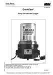
Owner Manual Technical Description 2.1A-30001-H06 Quicklub® Pump Model 203 for direct current VDC Subject to modifications 10011327 LINCOLN GmbH & Co. KG • Postfach 1263 • D-69183 Walldorf • Tel +49 (6227) 33-0 • Fax +49 (6227) 33-259 Owner Manual Technical Description 2.1A-30001-H06 All rights reserved. Any duplication of this User Manual, in its entirety or in part, by whatever means is prohibited without the prior consent in writing of Lincoln GmbH & CO. KG. Subject to modifications without prior notification. Phone: +49 (6227) 33-0 Fax: +49 (6227) 33-259 Subject to modifications © 2006 by LINCOLN GmbH & Co. KG Postfach 1263 D-69183 Walldorf Page 2 of 36 LINCOLN GmbH & Co. KG • Postfach 1263 • D-69183 Walldorf • Tel +49 (6227) 33-0 • Fax +49 (6227) 33-259 Owner Manual Technical Description 2.1A-30001-H06 Fields of Applications of the Quicklub Progressive Central Lubrication Pumps Industry - Machines - Commercial Vehicles Building Machinery - Agricultural Machines Wind Energy Plants Pump Types Pump Quicklub 203 Reservoir 2 l -2XN2),2XNFL2), 2YN3), 2XNBO1), 2YNBO3) 4 l -4XNBO1), 4YNBO3), 4XN2), 4XL2) 8 l - 8XNBO1), 8YNBO3), 8XN2), 8XL2) 15 l- 15XN1), 15XL1), 15XBF2) 1) Filling from the top or bottom 2) Filling only from the bottom 3) Filling only from the top 4l, 8l with lockable reservoir lid (option) Low-level control (option) possible with all reservoir sizes Control Without control unit for 12/24 VDC or 230 VAC Integrated control units ( V10-V13)4) for 12/24 VDC Integrated control units ( V10-V13)4) for 230 VAC Integrated control units with metering device monitoring (M 08 - M 23)4) Subject to modifications External control units PSG 01 (Commercial vehicles) PSG 02 (Industry) PSG E2 (Industry & Commercial vehicles) 4) 4) Control H Control V10 - ADR Control H - ADR 4) 4) See the respective model designation on the pump nameplate e.g. P203-2XN-1K6-24-1A1.10-V10 Page 3 of 36 LINCOLN GmbH & Co. KG • Postfach 1263 • D-69183 Walldorf • Tel +49 (6227) 33-0 • Fax +49 (6227) 33-259 Owner Manual Technical Description 2.1A-30001-H06 Table of Contents Page Page Fields of applications ...................................................... 3 Introduction Explanation of Symbols Used ............................................ User's Responsibility ......................................................... Environmental Protection .................................................. Service .............................................................................. Glossary ............................................................................ 5 5 5 5 5 Safety instructions Appropriate Use ................................................................ Misuse ............................................................................... General Safety Instructions ............................................... Regulations for Prevention of Accidents ............................ Disposal ............................................................................. Exclusion of Liability .......................................................... Operation, Maintenance and Repair .................................. Installation ......................................................................... 6 6 6 6 6 6 6 7 Installation ADR ................................................................................... Lines ............................................................................ Mounting of the Pump .................................................. Areas of Risk ............................................................... 8 8 9 9 Maintenance, Repair and Tests Maintenance .................................................................... Pump Filling ............................................................... Repair Pump .......................................................................... Replace pump element .............................................. Tests To check the pressure relief valve .............................. 20 20 21 21 21 Troubleshooting ............................................................. 22 Technical Data Pump ............................................................................... Motor ................................................................................ Pump elements ................................................................ Tightening torques ........................................................... Weights ............................................................................ Pressure relief valves ....................................................... Connection Diagram ........................................................ Dimensions ...................................................................... Attaching Bores ................................................................ 23 23 23 23 23 23 24 26 31 Lubricants ....................................................................... 32 Pump types .................................................................... 10 Identification Code ........................................................ 11 Subject to modifications Description The Quicklub 203 central lubrication pump ..................... 12 Low-level control, High-level control (option) ............. 12 Mode of operation Pump elements with fixed Lubricant output ..................... Pump element B7 with bypass check valve ............... Check valve ............................................................... Arrangement of the pump elements............................ Pump element with adjustable lubricant output ............... Setting of adjustable pump elements ......................... Retrofit adjustment of max. lubricant output ............... Retrofit adjusting of small lubricant outputs ............... Pressure relief valve ........................................................ - without grease return ..................................................... - with grease return (optional) .......................................... Return line connection ..................................................... Control unit ...................................................................... Low-level control - for grease ...................................................................... Reservoir filled ........................................................... When the reservoir is empty ...................................... High- and low-level control ......................................... Electromagnetic switch .............................................. - for oil Float magnetic switch ................................................ Contact protection measures ..................................... 13 13 14 14 14 15 15 16 16 16 16 17 17 18 18 18 18 19 19 19 Further information can be found in the following manuals: Technical Description Progressive Metering Devices for Grease and Oil, model SSV, SSV D and SSVM Printed Circuit Board 236-13862-1 - Model V10-V13 Printed Circuit Board 236-13870-2 - Model M 08-M 15 Printed Circuit Board 236-13870-2 - Model M 16-M 23 Installation Instructions Parts Catalog Parts Catalog Pump 203 Technical Description P203 DC Technical Description P203 AC Technical Description P203 with Follower Plate Lubricants External Printed Circuit Board 236-13894-1 Page 4 of 36 LINCOLN GmbH & Co. KG • Postfach 1263 • D-69183 Walldorf • Tel +49 (6227) 33-0 • Fax +49 (6227) 33-259 Owner Manual Technical Description 2.1A-30001-H06 Introduction Explanation of Symbols Used The following description standards are used in this manual: Safety Instructions Structure of safety instructions: Pictogram Signal word Danger text - Danger note - How to avoid danger The following pictograms are used in this manual and are combined with the corresponding signal words: 1013A94 - ATTENTION - CAUTION - WARNING 4273a00 - ATTENTION - CAUTION - WARNING 6001a02 - NOTE - IMPORTANT The signal words give the seriousness of danger if the following text is not observed: ATTENTION CAUTION WARNING NOTE IMPORTANT refers to faults or damages on machines. refers to bad damages and possible injuries. refers to possible dangerous injuries. indicates improved operation of the device. indicates special operating features of the device. Example: 1013A94 ATTENTION! When making use of other than the tested spare parts, serious damage may affect your device. Therefore, for the operation of your device always use original spare parts made by Lincoln GmbH & Co. KG. Furthermore, you will find the following text symbols in this manual: Listing of applicable statements - Subpoint of applicable statements 1. Determination of the number or sequence of contents  Procedural instruction User's Responsibility To ensure the safe operation of the unit, the user is responsible for the following: 1. The pump / system shall be operated only for the intended use (see next chapter "Safety Instructions") and its design shall neither be modified nor transformed. 2. The pump / system shall be operated only if it is in a proper functioning condition and if it is operated in accordance with the maintenance requirements. 3. The operating personnel must be familiar with this Owner Manual and the safety instructions mentioned within and observe these carefully. The correct installation and connection of tubes and hoses, if not specified by Lincoln GmbH & Co. KG, is the user's responsibility. Lincoln GmbH & Co. KG will gladly assist you with any questions pertaining to the installation. Environmental Protection Waste (e.g. used oil, detergents, lubricants) must be disposed of in accordance with relevant environmental regulations. Service The personnel responsible for the handling of the pump / system must be suitably qualified. If required, Lincoln GmbH & Co. KG offers you full service in the form of advice, on-site installation assistance, training, etc. We will be pleased to inform you about our possibilities to support you purposefully. In the event of inquiries pertaining to maintenance, repairs and spare parts, we require model specific data to enable us to clearly identify the components of your pump / system. Therefore, always indicate the part, model and series number of your pump / system. Glossary = = Operating time Lubrication cycle Subject to modifications Lubricating time Operating cycle Page 5 of 36 LINCOLN GmbH & Co. KG • Postfach 1263 • D-69183 Walldorf • Tel +49 (6227) 33-0 • Fax +49 (6227) 33-259 Owner Manual Technical Description 2.1A-30001-H06 Safety Instructions Appropriate Use Use the 203 pump only for dispensing lubricants in centralized lubrication systems. The pump is designed for intermittent operation. Misuse Any use of the 203 Pump that is not expressly mentioned in this Owner Manual will be regarded as misuse. If the 203 pumps used or operated in a different manner other than specified, any claim for warranty or liability will be null and void. NOTE 6001a02 If personal injury or material damage occurs as a result of inappropriate operation, e.g. if the safety instructions are ignored or resulting from an incorrect installation of the 203 pump, no claims or legal actions may be taken against Lincoln GmbH & Co. KG. General Safety Instructions Exclusion of Liability The manufacturer of the pump 203 will not accept any liability for damages: caused by the use of contaminated lubricants. caused by the use of greases which are not or only conditionally pumpable in centralized lubrication systems (see pages 32 ff). caused by chemical or biological modifications of the lubricant used. caused by inadequate disposal of used or contaminated lubricants as well as of components that have been in touch with lubricant. caused by unauthorized modification of the system components. caused by the use of unapproved parts. Operation, Maintenance and Repair Repair should only be performed by authorized and instructed personnel who are familiar with the instructions. Lincoln Quicklub centralized lubrication systems Quicklub centralized lubrication systems - are designed state-of-the-art. - can be assembled for safe operation. - must be filled regularly without air inclusions with clean lubricant recommended by the manufacturer. Incorrect use may result in bearing damage caused by poor or over-lubrication. Unauthorized modifications or changes to an installed system are not admissible. Any modification must be subject to prior consultation with the manufacturer of the lubrication system. caused by a lack of lubricant due to an irregular refilling of the pump. - must be operated only with installed pressure relief valve. - must be refilled in regular intervals with clean lubricant recommended by the manufacturer without air entrapments. - operate automatically. However, a regular check (approx. every 2 days) should be made to ensure that lubricant is emerging from all lubrication points. CAUTION! Regulations for Prevention of Accidents To prevent accidents, observe all city, state and federal safety regulation of the country in which the product will be used. Danger of squeezing in case of pumps to be filled from the reservoir top: Never put your hand into the open reservoir while pump is running! 6445b05 - Avoid the operation with ATTENTION! - unapproved parts. - insufficient or contaminated lubricants. Disposal 1013A94 Dispose of used or contaminated lubricants as well as of parts that were in touch with lubricant according to the legal regulations pertaining to environmental protection. Make sure to observe the safety data sheets of the lubricants used. Subject to modifications Risk of bursting if the reservoir is overfilled! When filling the reservoir by means of pumps with a large delivery volume do not exceed the max. filling mark. Page 6 of 36 LINCOLN GmbH & Co. KG • Postfach 1263 • D-69183 Walldorf • Tel +49 (6227) 33-0 • Fax +49 (6227) 33-259 Owner Manual Technical Description 2.1A-30001-H06 Safety Instructions, continuation Installation Any safety equipment already fitted to the vehicle or the machine: 1. The ADR Quicklub central lubrication pump complies with the design regulations of annex B of the act governing the road haulage of hazardous materials valid for Europe 1) (ADR ) and that valid for the Federal Republic of Ger2) many (GGVS ) 2. Moreover, the pump and its electrical equipment comply with the regulations of annex B.2 (ADR / GGVS regulations for electrical equipment) according to Rn 220000 in conjunction with the transport units mentioned in Rn 10251. 3. The ADR central lubrication pump is in conformity with the protection class IP 54. - should not be modified or made ineffective; - should only be removed for the purpose of fitting the system; - must be replaced afterwards. Keep Quicklub centralized lubrication systems away from sources of heat. Adhere to the operating temperature. Use only original Lincoln spare parts (see Parts Catalog) or parts approved by Lincoln. Adhere to: CAUTION! - the installation instructions of the vehicle or machine manufacturer as regards all drilling and welding procedures. It is not allowed to use the pump in other potentially explosive fields. - the specified minimum distances between the bore holes and the upper/lower rim of the frame or between two bore holes. IMPORTANT 6001a02 4. Install the ADR Quicklub 203 pump, the metering devices, lines and tube fittings as well as the electrical connection parts in accordance with the Installation Instructions. Use only original Lincoln parts. 5. After completion of the proper installation and commissioning, the installation of the system must be certified by means of a stamp and signature of the specialized workshop or expert. For this purpose, use the form attached to the Operating Instructions (pump 203). 6. If the pump and the installation do not comply with the construction regulations of ADR and GGVS, the type approval is no longer valid. 7. The Operating Instructions along with the certificate duly filled in must be added to the vehicle papers. It is to be submitted at the inspection in accordance with § 6, clause 4 GGVS. Only for use in commercial vehicles. 6001a02 IMPORTANT  Route supply lines professionally.  Firmly bolt together pressurized components. Subject to modifications 6001a02 Page 7 of 36 LINCOLN GmbH & Co. KG • Postfach 1263 • D-69183 Walldorf • Tel +49 (6227) 33-0 • Fax +49 (6227) 33-259 Owner Manual Technical Description 2.1A-30001-H06 Installation Specifications for the installation of electric equipment for ADR-application in comercial vehicles Lines - must be fixed by means of clamps or strips to prevent them from rubbing, sagging or getting loose, - must be protected from shocks, stone impact and heat, - other than in a fixed installation, must be sufficiently flexible in spite of their covering. The electric circuits can optionally be interrupted by singleor double -pole disconnecting switches. In case of single-pole disconnecting switches, the negative conductor must be able to be interrupted. For avoidance of short-circuits, please note the following: 4244a99 Fig. 1 Measures of protection for electric lines 1Conductor insulation 3Frame 2Conductor 4Coating current return lines must be insulated they must be connected to the vehicle frame (MASS 31) below the driver’s cab. housings and connectors must be of protection class IP 54 according to DIN 40050 plastic tubes must be of polyamide, tube coverings must be of polyurethane according to DIN VDE 0250 (only use original Lincoln ADR tubes). Mounting of the Pump – Areas of Risk According to paragraph 9.7.8 of the ADR directive, vehicles with hazardous goods type FL are divided into zones, according to the EX prescriptions, see Fig. 2. These are the correspondences: - tank inside zone 0, - fitting cabinet zone 1 - shut-off devices zone 1 - venting devices zone 1 Zone 2 is located around zones 0 and 1. The installation of the centralized lubrication system is allowed outside of zones 0, 1 and 2, only, whereby the extension is not determined in the ADR directive. Subject to modifications Page 8 of 36 LINCOLN GmbH & Co. KG • Postfach 1263 • D-69183 Walldorf • Tel +49 (6227) 33-0 • Fax +49 (6227) 33-259 Owner Manual Technical Description 2.1A-30001-H06 Installation, continuation Subject to modifications Mounting of the Pump – Areas of Risk, continuation 4332a01 Fig. 2 Areas of risk on vehicles with hazardous goods Page 9 of 36 LINCOLN GmbH & Co. KG • Postfach 1263 • D-69183 Walldorf • Tel +49 (6227) 33-0 • Fax +49 (6227) 33-259 Owner Manual Technical Description 2.1A-30001-H06 Pump Types 1173a95 Fig. 3 The different types of pump 203 Pumps 203 Control unit models 203 The 203 pumps differ from each other only in the design and reservoir size as well as in the type of the electric connection (different plugs with or without electric cable). Reservoir sizes: 2 l transparent plastic reservoir 4 l transparent plastic reservoir 8 l transparent plastic reservoir Electric connection For the industrial applications, the pumps are only equipped with plugs. The pumps model 203 used in commercial vehicles are equipped with a 10 m electric cable. The following control units can be used for the 203 pumps: (refer to the respective Technical Description) external control units PSG 01 PSG 02 (Industry) PSG E2 (Industry & Commercial vehicles) integrated control units 1) with adjustable pause and lubricating times, V10-V13 1) with adjustable pause and lubricating times, V10-V13 for alternate current 120, 230 VAC, separate owner manual with metering device monitoring (microprocessor control), 1) M 08 - M 23 c) integrated control unit (trailers) with fixed time of availability (6 hours) and adjustable 1) lubricating time, H 1) Refer to the designation on the pump nameplate. Example: P203 -2XNBO - 1 K6 - 24 - 2A1.10 - V10 Also refer to the designation code on page 11. Subject to modifications All other data such as: motor voltage version of the control unit remote control for triggering an additional lubrication cycle (2A1, 1A6, 1A7) design and number of pump elements design and number of pressure relief valves filling type use of return line connections low - level control (option) can be learnt from the pump type designation code. a) b) Page 10 of 36 LINCOLN GmbH & Co. KG • Postfach 1263 • D-69183 Walldorf • Tel +49 (6227) 33-0 • Fax +49 (6227) 33-259 Owner Manual Technical Description 2.1A-30001-H06 Identification Code - Pump Models 203 Examples of model designations NOTE 6001a02 Any pumps combinations other the above standard pumps can be composed and ordered in accordance with the valid model identification code. P203 - 2 - X - N - 1 - K6 - 24 - 1A - 1. - 01 - V10 P203 - 4 - X - L - 1 - K7 - 24 - 2A - 1. - 10 - V12 P203 - 2 - X - N - 1 - K6 - 12 - 1A - 8. - 00 P203 - 8 - X - L - 1 - K6 - 24 - 2A - 1. - 11 - V10- ADR P203 - 4 - Y - N - BO - 2 - K5 - 24 - 1A - 1. - 01 P203 - 4 - X - L - BO - 1 - K6 - 24 - 3A - 2. - 13 - M08 Basic pump model for grease or oil with 1-3 outlets and 12 VDC or 24 VDC motor Reservoir design 2 = 2 l transparent plastic reservoir 4 = 4 l transparent plastic reservoir 8 = 8 l transparent plastic reservoir X = Reservoire for grease Y = Reservoire for oil N = Standard design L = Low - level control without designation = Standard reservoire (2 Litre) BO = Filling from top FL = Flat-type reservoire (2 Litre) BF = Follower plate with high- and low-level control Pump elements 1-3 = Number of the use elements K 5 = Piston diameter = 5 mm K 6 = Piston diameter = 6 mm K 7 = Piston diameter = 7 mm KR = Pump element, adjustable, piston-Ø = 7 mm B 7 = Piston diameter = 7 mm (output from K5) S 7 = Piston diameter = 7 mm (for greases containing silicone) 3) C7 = Piston diameter = 7 mm 3) C 7 = Designation of pump elements for supplying of paste for chisel (C = chisel), C 5 or C 6 on reques Supply voltage 12 = 12 VDC (square-type plug, bayonet plug, M12 plug) 24 = 24 VDC (square-type plug, bayonet plug, M12 plug) AC = 120-230 VAC (square-type plug) 5) Number of electric connecting possibilities (on pump housing only) 1A = 1 connection DC, AC 5) - 1A: power supply (only with square-type plug) left bottom 2A = 2 connections 4) - 1A: power supply (only with square-type plug) left bottom, DC - 2A: illuminated pushbutton / low-level control (right bottom) or piston detector (right top) (see below 3A = 3 connections) 3A = 3 connections 5) - 1A: power supply (only with square-type plug) left bottom, AC 5) - 2A: illuminated pushbutton + low-level control (bayonet plug) left top - 3A: piston detector (bayonet plug) right top 4) 1A: no connection provided for low-level control for oil 2A: with illuminated pushbutton only 5) Equipment described in separate documentation Type of connection - 1 = cube-type plug, acc. to DIN 43650, type of construction A 1) - 2 = M12 plug - 6 = bayonet plug, 7/5 pole, M08-M23 - 7 = bayonet plug, 7/6 pole, V10-13, V20-23 - 8 = PG - cable gland Subject to modifications Connection outside the pump - 00 = without socket-outlet, without cable - 01 = with socket-outlet, without cable - 10 = with 10 m cable - 11 = with 10 m ADR cable - 13 = with 10 m cable, 5 - wire (microprocessor M08 - M23) - 15 = bayonet socket with 10 m cable, 7/5 core - 16 = bayonet socket with 10 m cable, 7/6 core Control p. c. b. s. 12V / 24 V V10 -V13 -with adjustable pause and operating time V10 -V13 - ADR with adjustable pause and operating time 2) M 08 ...M 23* - with microprocessor control (various 1) adjustments - see combinations of the jumper - positions) H - for trailer or semitrailers 2) H - ADR for trailers and semitrailers No designation: Pump without control p. c. b. 1) 2) Not in conjunction with square-type plugs (type of connection 1) For transport of hazard materials Page 11 of 36 LINCOLN GmbH & Co. KG • Postfach 1263 • D-69183 Walldorf • Tel +49 (6227) 33-0 • Fax +49 (6227) 33-259 Owner Manual Technical Description 2.1A-30001-H06 Description The Quicklub 203 central lubrication pump is a compact multiline pump consisting of the following components: - Housing with integrated motor - Reservoir with stirring paddle - Printed circuit board - Pump element - Pressure relief valve - Filling nipple - Electrical connection parts can drive up to 3 pump elements operates according to operating cycles (pause and lubricating times) can be equipped with a low-level control can supply up to 100 lubrication points depending on the line lengths is designed for the automatic lubrication of the connected lubrication points is designed for the delivery of greases up to NLGI 2 at temperatures from - 25° C to 70° C or of mineral oils of at least 40 mm²/s (cST) 00002618b Fig. 4 1234- Pump components Reservoir Pump element Safety valve Filling nipple, system Emergency lubrication possible 56789- Plug 2A1 Filling nipple, pump Printed circuit board Plug 1A1 Return line connection can be used at low temperatures down to - 40° C. During the operating time, the pump dispenses lubricant to the connected lubrication points via one or several metering devices. Low-level control (optional) The pump model 203 can be equipped with a low-level control. The following versions are available: - Low-level control in conjunction with printed circuit boards V10-V13 1) - Low-level control in conjunction with printed circuit board 1) M08-M23 - Low-level control for pumps without printed circuit board. When the reservoir is empty, the signal lamp flashes, thus indicating the low level. Refer to the chapter Low-level control, page 18. 1) Subject to modifications The designation indicates the version of the printed circuit board. It is part of the pump type designation code mentioned on the nameplate of each pump. Example: P203 - 2XN - 1K6 - 24 1A1.10 - V10 1006a93 Fig. 5 Quicklub central lubrication pump, 2 l reservoir Page 12 of 36 LINCOLN GmbH & Co. KG • Postfach 1263 • D-69183 Walldorf • Tel +49 (6227) 33-0 • Fax +49 (6227) 33-259 Owner Manual Technical Description 2.1A-30001-H06 Mode of Operation Pump elements with fixed lubricant output The electric motor drives the eccentric (pos. 1, Fig. 7 and 8). During the lubricating time: - piston 2 sucks in lubricant from the reservoir, (see Fig. 7). - piston 2 dispenses the lubricant to the connected lubrication points via the metering device (see Fig. 8). The following designs are available: - Piston diameter, K5 ........................................... 5 mm Lubricant output............................... approx. 2 cm³/min - Piston diameter K6 (standard) ............................ 6 mm Lubricant output............................ approx. 2,8 cm³/min 20002068 Fig. 6 13- Pump element Piston Check valve 2- - Piston diameter, C7 ........................................... 7 mm Lubricant output .............................. approx. 4 cm³/min - Piston diameter, B7 ........................................... 7 mm Lubricant output............................... approx. 2 cm³/min Return spring 1) - Piston diameter, K7, S7 .................................. 7 mm Lubricant output .............................. approx. 4 cm³/min 1) Pump element S7 suitable for lubricants containing silicone 1004b04 1003b04 Fig. 7 The pump element sucks in lubricant 1Eccentric 2Piston Fig. 8 The pump element dispenses lubricant 3Return spring 4Check valve Pump element B7 with bypass check valve 6251b04 Subject to modifications Fig. 9 Pump element B7 Pump element B7 suits especially applications in contaminated environments as the supplied lubricant is passing through a bypass bore (pos. 2, Fig. 10) on the check valve (pos. 1, Fig. 10). The output is 2 cm³/min. 6250b04 Fig. 10 Sectional diagram - pump element B7 1Check valve 2Bypass 3Pump piston 4Return spring Page 13 of 36 LINCOLN GmbH & Co. KG • Postfach 1263 • D-69183 Walldorf • Tel +49 (6227) 33-0 • Fax +49 (6227) 33-259 Owner Manual Technical Description 2.1A-30001-H06 Mode of Operation, continuation Check valve The check valve: - closes the pressure line during suction stroke - prevents the lubricant from flowing back to the housing or reservoir 1 2 3 4 R p 1164b95 Fig. 11 - Reservoir with stirring paddle Pump Check valve, spring-loaded Pressure relief valve Return line Pressure line Hydraulic diagram of the pump Arrangement of the pump elements If several pump elements are to be installed, the installation arrangement shown in Fig. 12 must be adhered to. If there is only one pump element , it can be installed in any position. Standard position is no. 3. If there are two elements, install one in position 3 and the other in position 1. 1163a95 Fig. 12 Arrangement of the pump elements Subject to modifications Pump element with adjustable lubricant output The mode of operation (suction and supply phase) is the same as that of the pump elements with an invariable lubricant output. The lubricant outputs are adjustable from 0.04 to 3 3 0.18m /stroke, or 0.7 to 3cm /min. The pump elements are factory-adjusted to the maximum lubricant output; the adjusting dimensions “S” should be 29 ± 0.1 mm. 4158a99 Fig. 13 Adjustable pumpelement Page 14 of 36 LINCOLN GmbH & Co. KG • Postfach 1263 • D-69183 Walldorf • Tel +49 (6227) 33-0 • Fax +49 (6227) 33-259 Owner Manual Technical Description 2.1A-30001-H06 Mode of Operation, continuation 4159a98 Fig. 14 12- Sectional view: adjustable element adjusting spindle SW 16 (with over flats) counternut SW 24 345- pump element body gasket pump cylinder 67S- control piston delivery piston dimension Setting of adjustable pump elements  Unscrew the coupling nut for fixing the safety valve. 1)  Loosen counter nut (pos. 2 ) while holding in position pump element body (pos. 3) by means of a second wrench.  Change the position of the adjusting spindle (pos. 1) by means of a wrench.  The dimension “S” (see Fig. 14) for the desired lubricant output can be ascertained by using the delivery diagram shown in Fig. 15. Retrofit adjustment of max. lubricant output NOTE 6001a02 4179a99 Fig. 15 Supply diagram ALubricant output cm3/min BLubricant output cm3/stroke SDimension In order to ensure that the lubricant output setting will be as exact as possible, first the actual dimensions “S” of the max. lubricant output must be ascertained as follows. The measured difference from the nominal value 29 must be considered for all other settings values (e.g. ± 0.1). 1)  Unscrew the adjusting spindle (pos. 1 ) from the pump element body (pos. 3) until “S” is approx. 30 mm. Subject to modifications  Screw counter nut (2) onto stop collar of the adjusting spindle (pos. 1)  Screw adjusting spindle (pos. 1) with counter nut (pos. 2) into pump element body (pos. 3) until stop. 1) All indications of positions refer to Fig. 14. Page 15 of 36 LINCOLN GmbH & Co. KG • Postfach 1263 • D-69183 Walldorf • Tel +49 (6227) 33-0 • Fax +49 (6227) 33-259 Owner Manual Technical Description 2.1A-30001-H06 Mode of Operation, continuation Adjusting of small lubricant outputs  Before the pump element can be adjusted to a small lubricant output, the dimension “S” for max lubrcant output must be ascertained, and the difference from the nominal value 29 must be tranferred to any desired settings between 25.5 ... 28,.5. NOTE At maximum steeing “S” is 29 ±0.1 mm. 6001a02  Dimension “S” must be adjusted to the desired value in accordance with the delivery diagramm (Fig. 15, page 15). Pressure Relief Valve IMPORTANT Each pump element must be secured with a pressure limiting valve. 6001a02 The pressure relief valve - limits the pressure build-up in the system - opens at an overpressure of 250 or 350 bar depending on the safety valve design. If lubricant is leaking at the pressure relief valve, this indicates that the system is malfunctioning. 10022618a Fig. 16 Pressure relief valve NOTE 6001a02 Between a malfunction (blockage) and the following fault indication (lubricant leakage; monitoring intermittent LED display on the control p.c.b., SPS) there may be a longer time delay. The duration of the delay depends on the type and length of the lines, the type of lubricant, the ambient temperature and other influences. Despite existing fault monitoring devices a regular visual and function control must be carried out on the lubrication system. Pressure relief valve with grease return (optional) Subject to modifications If the system is blocked, grease will leak from the pressure relief valve. This grease quantity is returned to the reservoir. 00002626a Fig. 17 Pressure relief valve with grease return Page 16 of 36 LINCOLN GmbH & Co. KG • Postfach 1263 • D-69183 Walldorf • Tel +49 (6227) 33-0 • Fax +49 (6227) 33-259 Owner Manual Technical Description 2.1A-30001-H06 Mode of Operation, continuation Pressure relief valve with grease return, continuation In the case of a blockage in the system, the grease pushes out the red pin at the pressure relief valve, thus indicating that there is a fault. The lubricant quantities which cannot be dispensed by the metering device must be returned to the pump via the return line connection (Fig. 19). 00002629a Fig. 18 Fault indication in the case of a blockage Return Line Connection 10032618 Fig. 19 Return line connection Control Unit NOTE 6001a02 Subject to modifications The present Technical Description describes the ”Pump model 203 without control unit”. Information concerning the design and operation of the individual control units can be found in the respective Technical Descriptions. If the pump is to be equipped with a control unit, it is possible to use an integrated printed circuit board or an external control unit. 00002616 Fig. 20 Printed circuit board integrated in the housing Page 17 of 36 LINCOLN GmbH & Co. KG • Postfach 1263 • D-69183 Walldorf • Tel +49 (6227) 33-0 • Fax +49 (6227) 33-259 Owner Manual Technical Description 2.1A-30001-H06 Mode of Operation, continuation Low Level Control (optional) For grease Reservoir filled The stirring paddle rotates clockwise during the lubricating time. The entry of the stirring paddle (B) into the lubricant presses the pivoted guiding plate with the round solenoid (pos. 1) inwards to orbit A. The solenoid switch (pos. 2) cannot be activated contact-free. Control cam item 3 guides the round solenoid with the pivoting guiding plate automatically outwards, in the direction of the reservoir wall. When leaving the control cam, the lubricant presses against the guiding plate and moves the solenoid inwards again (B). 6398b05 Fig. 21 1- Guiding plate with round solenoid Electromagnetic switch Control cam 23- NOTE The switch parts of the low-level control (items 1 to 3) cannot be used with fluid greases (see fig. 24, page 19). Switching parts of the low-level control (reservoir filled) AB- Inner orbit of the round solenoid Position of the guiding plate (entered) 6001a02 When the reservoir is empty When passing the control cam (pos. 3) the solenoid remains in the outer orbit (C) and thereby passes the solenoid switch (pos. 2). The solenoid activates the solenoid switch contact-free and so initiates a low-level indication. When the stirring paddle rotates on the outer orbit (C) there is no counterpressure by lubricant. The guiding plate with the round solenoid (1) remains unentered (D). 6397b05 Fig. 22 1- CB- Outside orbit of the round solenoid Position of the guiding plate (unentered) Subject to modifications 23- Switching parts of the low-level control (reservoir empty) Guiding plate with round solenoid Electromagnetic switch Control cam Page 18 of 36 LINCOLN GmbH & Co. KG • Postfach 1263 • D-69183 Walldorf • Tel +49 (6227) 33-0 • Fax +49 (6227) 33-259 Owner Manual Technical Description 2.1A-30001-H06 Mode of Operation, continuation Electromagnetic switch The electromagnetic switch is activated free of wear and free of contact by means of the magnetic field of the solenoids on stirring paddle. Technical data Maximum switching capacity ................................. 60VA Maximum switching voltage .................................. 230 V Current switched ....................................................... 3 A NOTE 4237a03 Fig. 23 Connection diagram without control unit, low-level control (optional) for grease 6001a02 The life of the float magnetic / magnetic circuit breaker strongly depends on the conditions under which it is loaded. Since the data relative to the maximum switching capacity refer to strictly resistive loads, which cannot be always guaranteed in practice, it is necessary to take the corresponding contact protection measures in the case of deviating loads. for oil: Float magnetic switch Operating mode Float magnetic switches are equipped with hermetically sealed reed contacts. The reed contacts are activated by the magnetic field of a ring solenoid included in the float totally free of wear and without contact. The only movable component of the float magnetic switch is the float that moves up and down with the liquid reliably on the slide tube. Technical data Maximum switching capacity ................................. 60VA Maximum switching voltage .................................. 230 V Current switched ....................................................... 1 A 1202a99 Fig. 24 Connection diagram, low-level control for oil Contact protection measures Subject to modifications 1201a95 Fig. 25 Contact protection measures 1Electromagnetic switch 2RC element 3Diode 4Load Page 19 of 36 LINCOLN GmbH & Co. KG • Postfach 1263 • D-69183 Walldorf • Tel +49 (6227) 33-0 • Fax +49 (6227) 33-259 Owner Manual Technical Description 2.1A-30001-H06 Maintenance, Repair and Tests Maintenance The maintenance is essentially limited to refilling the reservoir with clean lubricant in good time. However, check regularly whether the lubricant is really dispensed to all the lubrication points. NOTE Also check the main lines and lubricant feed lines for damage and replace them, if necessary. 6001a02 Whenever work is done on the centralized lubrication system, particular attention should be paid to absolute cleanliness. Dirt in the system will cause problems. For cleaning the system use benzine or petroleum. Do not use tri-, perchloroethylene or similar solvents. Also do not use polar organic solvents such as alcohol, methylacohol, acetone or similar. Pump Filling 2 l, 4 l , 8 l - reservoirs Fill the reservoir up to the ”Max.” mark via the filling nipple (see Fig. 26), via the filling fitting for cartridges (see Fig. 27) if any, or via the upper filling opening. It is possible to use greases up to penetration class NLGI 2 or mineral oils of at least 40 mm²/s (cST). IMPORTANT The grease or oil must be free from impurities and must not be liable to change its consistency in the course of time. 6001a02 CAUTION! Danger of squeezing in case of pumps to be filled from the reservoir top: Never put your hand into the open reservoir while pump is running! 6347b04 Fig. 26 Fill pump reservoir 6445b05 CAUTION! Risk of bursting if the reservoir is overfilled. 1013A94 When filling the reservoir by means of pumps with a large delivery volume, do not exceed the max. filling mark. NOTE If the reservoir has been completely emptied, the pump may require up to 10 minutes before it operates at full output. 6001a02 6593b06 Subject to modifications Fig. 27 Manual bottom filling of pump reservoir Repair Pump Use only original Lincoln spare parts for repair on the pumps. The pump should be returned to the factory for warranty work or major repairs. Page 20 of 36 LINCOLN GmbH & Co. KG • Postfach 1263 • D-69183 Walldorf • Tel +49 (6227) 33-0 • Fax +49 (6227) 33-259 Owner Manual Technical Description 2.1A-30001-H06 Maintenance, Repair and Tests, continuation Repair, continuation Replace pump element  Remove the pressure relief valve from the pump element  Unscrew the pump element. Take care that the piston, the pull-back spring and the washer are not left lying in the grease, otherwise the reservoir must be disassembled in order to remove these pieces IMPORTANT 6001a02 Do not leave the piston, spring and washer in the housing because they may block the motor.  Install a new pump element and a new sealing ring. NOTE 6001a02 Pump element with adjustable lubricant output is set to the same output as the old pump element. 5026a96 Fig. 28 Replacing the pump elememt Tests Operational Test / Triggering an Additional Lubrication Cycle To check the pump operation it is possible to perform an additional test. Refer to the Technical Description of the respective printed circuit board. To Check the Pressure Relief Valve 1st option  Connect the pressure gauge (0-600 bar; 0-8708 psi) to the pressure relief valve (Fig. 16, page 16).  Trigger an additional lubrication cycle. 2nd option  Connect the manual pump of the pressure and checking set 604-36879-1 to the pressure relief valve and check the opening pressure by means of the manual pump.  The pressure relief valve should open at a pressure of 200, 270 or 350 bar depending on its design. IMPORTANT Subject to modifications 6001a02 1005a93 Fig. 29 1234- Do not connect the pressure gauge directly to the pump element. High pressure may exceed the above mentioned range, causing the motor to stall. The motor is designed in such a way that it can stall for about 30 minutes without being damaged. Hose line, min.length 1m T-piece Pressure gauge Relief cock To check the pressure relief valve Page 21 of 36 LINCOLN GmbH & Co. KG • Postfach 1263 • D-69183 Walldorf • Tel +49 (6227) 33-0 • Fax +49 (6227) 33-259 Owner Manual Technical Description 2.1A-30001-H06 Troubleshooting NOTE The pump operation can be checked from the outside by observing whether the stirring paddle is rotating (e.g. by triggering an additional lubrication). 6001a02 For troubleshooting in the case of pumps with integrated control units, please refer to the respective Technical Description of the printed circuit board. Fault: The pump motor does not run Cause : Power supply interrupted Remedy:  Check the power supply and fuses. If necessary rectify the fault and/or replace the fuses.  Check the power supply to the motor. If necessary, replace the motor.  Check the line leading from the fuses to the pump plug. Electric motor defective Fault: The pump does not deliver the lubricant Cause : Remedy: NOTE 6001a02 Reservoir empty If a lubricant low-level is available, the low level is indicated by the flashing light of the signal lamp in the case of pumps without printed circuit board. The flashing frequency depends on the speed of the motor.  Fill up the reservoir with clean grease or oil. Allow pump to run (trigger an additional lube cycle) until the lubricant issues from all the lubrication points. NOTE 6001a02 Air bubbles in the lubricant Depending on the ambient temperature and/or sort of lubricant it may take 10 minutes of operation before the pump elements reach their full lubricant output.  Trigger an additional lubrication cycle. Loosen the outlet fitting or the main line at the pressure relief valve. The lubricant must issue without air bubbles. NOTE 6001a02 When push-in type fittings are used, the high-pressure hose which is under pressure cannet be easily disconnected from the pressure relief valve. For this purpose, loosen the pressure relief valve. For this purpose, filling nipple on the pressure relief valve in order to relieve the high-pressure hose. Unsuitable lubricant has been used  Renew the lubricant. See the Lubricant List (see page 33 and 34). Suction hole of the pump element clogged  Remove the pump element. Check the suction hole for foreign particles. If there are any, remove them. Pump piston worn  Replace the pump element. Check valve in the pump element defective or clogged.  Replace the pump element. Subject to modifications Page 22 of 36 LINCOLN GmbH & Co. KG • Postfach 1263 • D-69183 Walldorf • Tel +49 (6227) 33-0 • Fax +49 (6227) 33-259 Owner Manual Technical Description 2.1A-30001-H06 Technical Data Pump 1) Admissible operating temperature ..............-25° C to 70° C Number of outlets.......................................................1,2 or 3 Reservoir capacity ................................................. 2 l, 4 l, 8 l Refilling .................via hydraulic lubrication fitting or from top Lubricant ....................................greases up to NLGI grade 2 & mineral oils of at least 40mm²/s (cST) at 40° C Class of protection ................. IP6K 9K acc. to DIN 40050 T9 1) 6001a02 NOTE The pump is designed for the above mentioned temperature range. The lubricants used must still be pumpable at the temperatures mentioned above. In case of doubt, consult the lubricant manufacturer. NOTE The pump reservoirs are factory-primed with lubrication grease Renocal FN745 and EP additives make Fuchs. This composition is compatible to most of the commercial greases and helps to prevent faults. If requested by the customer, the pumps can either be primed with another type of lubrication grease or be supplied without priming. Motor DC gear motor (interference-suppressed) - Operating voltage. ................................12VDC or 24VDC - Max. current input 12V .......................................................................... 6.5 A 24V ............................................................................. 3 A Speed ............................................................ approx.17 rpm Noise emission .................................................... < 70 dB(A) Pump element with fixed lubricant output Piston diameter, K5.......................................................5 mm - Lubricant output................................... approx. 2 cm³/min Piston diameter, (standard) K6 .....................................6 mm - Lubricant output................................. approx. 2.8cm³/min 3) Piston diameter, K7, C7, S7 .......................................7 mm - Lubricant output................................... approx. 4 cm³/min Max. operating pressure. ...........................................350 bar Connection thread......................................................... G 1/4 - suitable for tube DIA................................................6 mm 2) suitable for chisel paste; contact the manufacturer of the lubrication system 3) suitable for lubricants containing silicone Subject to modifications Pump element with adjustable lubricant output KR ............................................... 0.04 to 0.18 cm³/stroke .......................................................... 0.7 to 3 cm³/min Connection thread.................................................... G 1/4 in. - suitable for tube DIA................................................6 mm - suitable for tube DIA................................................8 mm 6001a02 IMPORTANT The lubricant output listed refers to grease of NLGI grade 2 measured at 20°C, backpressure 100 bar, nominal voltage 12/24 V. Any differing pressures or temperatures result in different lubricant outputs. Any system design must be based on the above values.compte. Pressure relief valve SVETVT-350-G 1/4A-D6 ................................... 624-28894-1 SVETVT-350-G 1/4A-D8 ................................... 624-28774-1 Torsion torques Install pump .................................................................18 Nm Electric motor on housing ............................................12 Nm Pump element in housing ............................................20 Nm Closure plug in housing ...............................................12 Nm Return line connector in housing ..........................10 - 12 Nm Weights The weights below include the following ‘‘individual weights”: - Pump kit with one pump element, pressure relief valve, grease filling (0.75 kg, 1.5 kg) - Packing (cardboard box) - Attaching parts - Operating Instructions 2 l reservoir, standard design (0.75 kg) - Pump 203 without connection cable .......................5.4 kg - Pump 203, version E 1............................................6.5 kg - Pump 203, version E 2............................................7.1 kg 4 l reservoir, standard design (1.5 kg) - Pump 203 without connection cable .......................8.3 kg Pump 203, version E 1............................................9.3 kg Pump 203, version E 2............................................9.9 kg 8 l reservoir, standard design (1.5 kg) - Pump 203 without connection cable .......................8.6 kg Pump 203, version 1A1...........................................9.6 kg Pump 203, version 2A1.........................................10.2 kg In the case of pump versions deviating from those mentioned, add the weights of the following components to the mentioned weights: - Per pump element................................................ +0.2 kg - Per pressure relief valve ...................................... +0.1 kg - 10 m monitoring cable, 5-wire (microprocessor) E 4............................................ +1.1 kg - 10 m monitoring cable, 4-wire (microprocessor) E 4............................................ +0.4 kg - Connection cable with piston detector ....................0.1 kg 3) - Reservoir version ”Filling from top” (only 2 l) ... +0.15 kg - 2 l flat-type reservoir ............................................ +0.5 kg 3) NOTE The 4l and 8l reservoirs have the standard design ”filling from top”. 6001a02 Page 23 of 36 LINCOLN GmbH & Co. KG • Postfach 1263 • D-69183 Walldorf • Tel +49 (6227) 33-0 • Fax +49 (6227) 33-259 Owner Manual Technical Description 2.1A-30001-H06 Technical Data, continuation Connection Diagrams Pumps without control unit 1165a06 Fig. 30 ABC- Connection diagram Quicklub P 203 VDC without control unit, connection: square-type connectors DIN 43650-A Pump housing Plug 1 Line socket 1 with connecting cable, - 5-core (if necessary, cut off black cable) - alternatively: connecting cable from the user Plug 2 1) 1) Line socket 1 DE1) F- M- Low-level control Switching capacity max. 60 W/VA Switching voltage max. 230 VAC Switched current max. 1 A Electric motor available with low-level control, only NOTE For further connection diagrams please see the respective Technical Description ”Electronic Control Units for Centralized Lubrication Pump Model 203”. Subject to modifications 6001a02 Page 24 of 36 LINCOLN GmbH & Co. KG • Postfach 1263 • D-69183 Walldorf • Tel +49 (6227) 33-0 • Fax +49 (6227) 33-259 Owner Manual Technical Description 2.1A-30001-H06 Technical Data, continuation Connection Diagrams, continuation Pumps without control unit, continuation 6595a06 Fig. 31 AB- Connection diagram Quicklub P 203 VDC without control unit, connection: bayonet plug (without low-level control) Pump housing Plug 1 CM- Line socket 1 with connecting cable, 4/2-core Electric motor 6569a06 Subject to modifications Fig. 32 ABC- Connection diagram Quicklub P 203 VDC without control unit, connection: M12 plug Pump housing Plug Line socket 1 with connecting cable, 5-core (1-5) - alternatively: connecting cable from the user 1 - brown 3 - blue 2 - white 4 - black 5 - green/yellow M - Electric motor F - Low-level control Switching capacity max. 60 W/VA Switching voltage max. 230 VAC Switched current max. 1 A Page 25 of 36 LINCOLN GmbH & Co. KG • Postfach 1263 • D-69183 Walldorf • Tel +49 (6227) 33-0 • Fax +49 (6227) 33-259 Owner Manual Technical Description 2.1A-30001-H06 Technical Data, continuation Subject to modifications Dimensions - 2 l Reservoir 1166a95 Fig. 33 Dimensions - 2 l Reservoir Page 26 of 36 LINCOLN GmbH & Co. KG • Postfach 1263 • D-69183 Walldorf • Tel +49 (6227) 33-0 • Fax +49 (6227) 33-259 Owner Manual Technical Description 2.1A-30001-H06 Technical Data, continuation Subject to modifications Dimensions - 2 l Reservoir with Filling from Top 1167a95 Fig. 34 Dimensions - 2 l Reservoir with Filling from Top Page 27 of 36 LINCOLN GmbH & Co. KG • Postfach 1263 • D-69183 Walldorf • Tel +49 (6227) 33-0 • Fax +49 (6227) 33-259 Owner Manual Technical Description 2.1A-30001-H06 Technical Data, continuation Subject to modifications Dimensions - 2 l Flat-Type Reservoir 1168a95 Fig. 35 Dimensions - 2 l Flat-Type Reservoir Page 28 of 36 LINCOLN GmbH & Co. KG • Postfach 1263 • D-69183 Walldorf • Tel +49 (6227) 33-0 • Fax +49 (6227) 33-259 Owner Manual Technical Description 2.1A-30001-H06 Technical Data, continuation Subject to modifications Dimensions - 4 l Reservoir 1169a95 Fig. 36 Dimensions - 4 l Reservoir Page 29 of 36 LINCOLN GmbH & Co. KG • Postfach 1263 • D-69183 Walldorf • Tel +49 (6227) 33-0 • Fax +49 (6227) 33-259 Owner Manual Technical Description 2.1A-30001-H06 Technical Data, continuation Subject to modifications Dimensions - 8 l Reservoir 1170a95 Fig. 37 Dimensions - 8 l Reservoir Page 30 of 36 LINCOLN GmbH & Co. KG • Postfach 1263 • D-69183 Walldorf • Tel +49 (6227) 33-0 • Fax +49 (6227) 33-259 Owner Manual Technical Description 2.1A-30001-H06 Technical Data, continuation Attaching Boreholes of the 2 l, 4 l, 8 l Pump 1171b03 Fig. 38 Attaching Boreholes of the 2 l, 4 l, 8 l Pump NOTE Thighten pump models with 2 L- Flat, 4 L - and 8 L reservoir with three fastening screws ( see pt. 9,5). Subject to modifications 6001a02 Page 31 of 36 LINCOLN GmbH & Co. KG • Postfach 1263 • D-69183 Walldorf • Tel +49 (6227) 33-0 • Fax +49 (6227) 33-259 Owner Manual Technical Description 2.1A-30001-H06 Lubricants 6001a02 IMPORTANT Absolute cleanness is essential when handling lubricants. Impurities will remain suspended in the lubricant and cannot settle. This will result in damage to the lubrication system and thus to the bearing. The Quicklub pump can dispense commercial greases up to NLGI grade 2 or mineral oils of at least 40 mm²/s (cST) at operating temperature. Lubricant recipes may change. In case of doubt, send your request for more information to the manufacturer of the centralized lubrication system. This refers in particular to lubricants with more than 3% graphite that are transportable in lubrication systems only conditionally. The lubricants released by us have not been tested with regard to their long-term behavior. IMPORTANT The manufacturer of the centralized lubrication system can accept no liability for: - damages due to the use of greases that 6001a02 are not or only conditionally transportable in centralized lubrication systems. - damages on parts of the centralized lubrication system caused by chemical or biological changes of the lubricant used. - damages due to the incompatibility with other materials. The liability is limited to transportable lubricants in centralized lubrication systems. Subject to modifications The proven lubricants (see following tables) have been tested by us with regard to their transportability and bleeding behavior. We can recommend them for an application up to the indicated minimum delivery temperature in Quicklub lubrication systems by Lincoln& Co. KG. During the tests these lubricants did not cause any damage due to incompatibility with the material used by us. The composition of the lubricants, their behavior during the transport and their compatibility with other material are not known to us. The lubricants we recommend on the basis of the manufacturer’s data sheet (see following tables) can be used in our lubrication systems up to the indicated minimum delivery temperature. Page 32 of 36 LINCOLN GmbH & Co. KG • Postfach 1263 • D-69183 Walldorf • Tel +49 (6227) 33-0 • Fax +49 (6227) 33-259 Owner Manual Technical Description 2.1A-30001-H06 Lubricants, continuation Quicklub List of Lubricants IMPORTANT Use lubricants with solid matter additives only after having consulted the manufacturer of the system! 6001a02 Proven lubricants Manufacturer Designation Base soap AGIP AUTOL ARAL AUTOL AUTOL BP BOSCH-REXROTH BOSCH-REXROTH ELKALUB FUCHS-LUBRITECH FUCHS FUCHS FUCHS FUCHS MOBIL MOLYKOTE OPTIMOL OPTIMOL RHENUS RHENUS SHELL SHELL WESTFALEN Universal grease Long-term grease H Top 2000 Top 2000 W C1 Multipurpose grease Dynalub 510 Dynalub 520 GLS 135/N2 Stabil Eco EP2 Renocal FN 745 Renocal FN3 Renolit LZR 2 H Renolit HLT 2 Mobilith SHC 100 TTF 52 Longtime PD 2 Olit CLS Norlith KSP 2 Norlith MZN 2 Retinax EPL 2 Retinax CSZ Gresalit ZSA 2 Li-12-OH-stearat Li-12-OH-stearat Ca-complex Ca-complex Ca Li Li Li Li/Ca Ca-12-OH-stearat Ca Li Li Li-complex inorganic thickener Li-12-OH-stearat Li/Ca Li + Li-12-OH stearat Li Li-12-OH-stearat Li/Ca Li-12-OH-stearat Min. delivery temperature -15 °C -15 °C -10 °C -20 °C -20 °C -15 °C -20 °C -15 °C -25 °C -25 °C -20 °C -20 °C -25 °C -25 °C -30 °C -20 °C -15 °C -15 °C -15 °C -10 °C -35 °C -15 °C Subject to modifications Lubricant recommendations based on the manufacturer’s data sheet Manufacturer Designation Base soap AGIP ARAL ARAL AVIA BP BP CASTROL / TRIBOL CASTROL CASTROL CASTROL DEA ESSO ESSO ESSO ESSO FIAT LUBRIFICANTI KLÜBER KLÜBER KLÜBER KLUEBER KLÜBER MOBIL MOBIL MOBIL MOBIL SHELL SHELL SHELL SHELL SHELL SHELL SHELL TEXACO TOTAL TOTAL TOTAL ZELLER & GMELIN F1 Grease 24 Multipurpose grease Multipurpose grease ZS 1/2 Avialith 2 EP Energrease LC 2 Energrease MP-MG 2 Molub Alloy 6780 CLS - Grease Olista Longtime 2 Optimol Olit 2 EP Glissando 20 Ronex Extra Duty 2 Ronex MP2 Beacon EP2 Cazar K2 Comar 2 Centoplex 1 DL Isoflex NBU 15 Klüberplex BEM 34-132 Klüberplex BEM 41-141 Petamo GHY 133 N Mobilgrease XHP 221 Mobilgrease XHP 461 Mobilgrease XHP 222 Mobilith SHC 220 Alvania EP(LF) 1 Alvania EP(LF) 2 Alvania RL2 Malleus GL Retinax CS Retinax LX 2 Retinax HDX 2 Premium RB Ceran AD Ceran LT Ceran WR2 Divinol Lithogrease G 421 Ca Li-12-OH-stearat Li/Ca Li-12-OH-stearat Li-complex Ca-complex Li-12-OH-stearat Li/Ca Li Li Li-12-OH-stearat Li-complex Li-complex Li Ca Li Li/Ca Ba Ca-complex Li-complex Polycarbamide Li-complex Li-complex Li-complex Li-complex Li-12-OH-stearat Li-12-OH-stearat Li-12-OH-stearat Gel Li Li Li/Ca Li Ca-complex Ca-complex Ca-complex Li-complex Min. delivery temperature -15 °C -15 °C -20 °C -15 °C -15 to -10 °C -5 °C -30 to -25 °C -25 °C -20 ° C -20 °C -15 to -10 °C 5 °C -5 °C -5 °C -15 °C -25 °C -20 °C -25 °C -20 °C -25° C -15 °C -10 °C -10 °C -5 °C -20 °C -15°C +/- 5°C -10°C +/- 5°C -15°C +/- 5°C GL205 -20 °C, GL300 -10 °C -20 °C -5°C +/- 5°C -10°C +/- 5°C -20 °C - 15° C -20 °C -10 °C -15 °C Page 33 of 36 LINCOLN GmbH & Co. KG • Postfach 1263 • D-69183 Walldorf • Tel +49 (6227) 33-0 • Fax +49 (6227) 33-259 Owner Manual Technical Description 2.1A-30001-H06 Lubricants, continuation Quicklub List of Lubricants, continuation IMPORTANT Use lubricants with solid matter additives only after having consulted the manufacturer of the system! 6001a02 Biodegradable lubricants Proven lubricants: Manufacturer Designation ARAL BP FUCHS-LUBRITECH Aralub BAB EP 2 Biogrease EP 2 Stabyl ECO EP 2 Lubricant recommendations based on the manufacturer’s data sheet: Manufacturer Designation AUTOL AVIA DEA FUCHS KLÜBER Top Bio 2000 Biogrease 1 Dolon E 2 Plantogel 2 S Klüberbio M72-82 Base soap Li/Ca Li/Ca Li/Ca Base soap Ca Li Li Li/Ca Polycarbamide min. delivery temperature -25 °C -25 °C -25 °C min. delivery temperature -25 °C up to 0 °C -15 °C -15 °C -20 °C Lubricants for the food & beverage industry Lubricant recommendations based on the manufacturer’s data sheet: Manufacturer Designation Grease EPF 2 Rivolta F.L.G 4 – 2 GLS 364 GLS 367/N2 GLS 380/N1 GLS 380/N2 Renolit G 7 FG 1 Gleitmo 585 M (KTW-drinking water release) Fin Food Grease EP Paraliq GA 343 Kluebersynth UH1 14-151 Mobilgrease FM 462 Special grease GLS 380/N3 470 Obeen UF 1 Obeen UF 2 AFD 2 AFP 2 AFS 2 AFW 2 Cassida Grease EPS 1 Cassida Grease EPS 2 Lubriplate FGL 2 FoodProof 823-2 FM 9830 high-temperature grease Base soap Al-complex Al-complex organic thickener inorganic thickener Al-complex Al-complex Bentonite Li Al-complex Al-complex Al-complex Al-complex Al-complex Li-12-OH-stearat Al-complex Al-complex Al-complex Al-complex Al-complex Al-complex Al-complex Al-complex Al-complex Al-complex PTFE min. delivery temperature -5°C -20 °C -10 °C -5°C -10 °C -5°C -5°C -10 °C -5°C -10 °C -20 °C -15 °C -5°C -15 °C -15 °C -10 °C -5°C -5°C -25 °C -5°C -15 °C -10 °C -5°C -15 °C 0°C Subject to modifications ARAL EURAL BREMER & LEGUIL ELKALUB ELKALUB ELKALUB ELKALUB FUCHS FUCHS-LUBRITECH INTERFLON KLUEBER KLUEBER MOBIL Nordischer Maschinenbau OKS OPTIMOL OPTIMOL RHENUS NORPLEX RHENUS NORPLEX RHENUS NORPLEX RHENUS NORPLEX SHELL SHELL TOTAL TRIBOL MOLUB-ALLOY TRIBOL MOLUB-ALLOY Page 34 of 36 LINCOLN GmbH & Co. KG • Postfach 1263 • D-69183 Walldorf • Tel +49 (6227) 33-0 • Fax +49 (6227) 33-259 Owner Manual Technical Description 2.1A-30001-H06 Subject to modifications Note: Page 35 of 36 LINCOLN GmbH & Co. KG • Postfach 1263 • D-69183 Walldorf • Tel +49 (6227) 33-0 • Fax +49 (6227) 33-259 Owner Manual Technical Description Subject to modifications 2.1A-30001-H06 America: Lincoln Industrial One Lincoln Way St. Louis, MO 63120-1578 USA Phone: (+1) 314 679 4200 Fax: (+1) 800 424 5359 Europe/Africa: Lincoln GmbH & Co. KG Heinrich-Hertz Straße 2-8 69190 Walldorf, Germany Tel: (+49) 6227 33-0 Fax: (+49) 6227 33-259 Asia/Pacific: Lincoln Industrial Corporation 51 Changi Business Park Central 2 # 09-06 The Signature Singapore 486066 Phone: (+65) 6588-0188 Fax: (+65) 6588-3438 Email: [email protected] © Copyright 2006 Printed in Germany Web site: www.lincolnindustrial.com Page 36 of 36 LINCOLN GmbH & Co. KG • Postfach 1263 • D-69183 Walldorf • Tel +49 (6227) 33-0 • Fax +49 (6227) 33-259