1
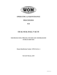
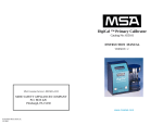
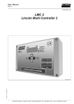
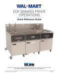
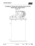
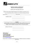
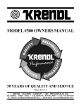
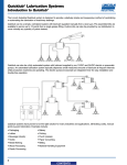
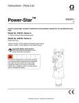
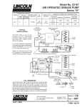
FlowMaster™ Rotary Driven Hydraulic Pump Models: 85480, 85481, 85482 and 85483 Series “A” Foreign and U.S. Patent Pending This pump conforms to the European Directive for Product Safety 7.5A-18100-A98 February 1999 Form 402864 Section - C8 Page - 269A FlowMaster™ Rotary Driven Hydraulic Pump Series “A” Table of Contents Page Safety ….……………………................................................................2 Description....................................................................................2 Appropriate Use................................................................2 Pump Performance and Specifications..............................3 Installing the Pump.....................................................................4 Operation.....................................................................................5 Maintenance and Repair...........................................................5 Pump Dimensions.............................................................7 Repair Parts List................................................................................9 Trouble Shooting.........................................................................10 Safety Read and carefully observe these operating instructions before unpacking and operating the pump! The pump must be operated, maintained and repaired exclusively by persons familiar with the operating instructions. Local safety regulations regarding installation, operation and maintenance must be followed. Operate this pump only after safety instructions and this service manual are fully understood. Indicates a potentially hazardous situation which, if not avoided, could result in death or serious injury. Indicates a potentially hazardous situation which, if not avoided, may result in minor or moderate injury. Safety Instructions This equipment generates very high grease pressure. Extreme caution should be used when operating this equipment as material leaks from loose or ruptured components can inject fluid through the skin and into the body causing serious bodily injury. Adequate protection is recommended to prevent splashing of material onto the skin or into the eyes. service center nearest you for repair or adjustments other than maintenance specified in this manual. Annual inspection by the factory authorized warranty and service center nearest you is recommended. A list of factory authorized warranty and service centers is available upon request. Damaged Pumps Any pump that appears to be damaged in any way, is badly worn or operates abnormally, shall be removed from use until repairs are made. Contact the factory authorized warranty and service center nearest to you for repairs. Description 85480 85481 85482 85483 - Pump Pump Pump Pump for for for for 120 pound drum (16 gallon) 60 pound drum 400 pound drum (55 gallon) 5 gallon pail General Description The Lincoln Industrial rotary Hydraulic Pump is a fully hydraulically operated grease pump. Grease output is proportional to the hydraulic input flow. The pump is primarily designed for centralized lubrication systems such as the Single Line Parallel, Single Line Progressive and Two Line systems. An integrated pump control manifold is incorporated with the motor to control input flow and pressure. A 24 volt DC solenoid valve is also incorporated as a method to turn the pump on and off. The pump is driven by the rotary motion of the hydraulic motor. Rotary motion is converted to reciprocating motion through an eccentric crank mechanism. The reciprocating action causes the pump cylinder to move up and down. The pump is a positive displacement double acting pump as grease output occurs during both the up and down stroke of the pump. If any fluid appears to penetrate the skin, get emergency medical care immediately. Do not treat as a simple cut. Tell attending physical exactly what fluid was injected. During the down stroke, the pump cylinder is extended into the grease. Through the combination of shovel action and vacuum generated in the pump cylinder chamber, the grease is forced into the pump cylinder. Simultaneously, grease is discharged through the outlet of the pump. The volume of grease during intake is twice the amount of grease output during one cycle. During the upstroke, the inlet check closes, and one half of the grease taken in during the previous stroke is transferred through the outlet check and discharged to the outlet port. Typical output of the pump is shown on page 4. Inspection Appropriate Use If overpressurizing of the equipment is believed to have occurred, contact the factory authorized warranty and service center nearest you for inspection of the pump. Specialized equipment and knowledge is required for repair of this pump. Contact the factory authorized warranty and Page Number - 2 All pump models are exclusively designed to pump and dispense lubricants using hydraulic power. The maximum specification ratings should not be exceeded. Any other use not in accordance with instructions will result in loss of claims for warranty and liability. 7.5A-18100-A98 Form 402864 FlowMaster™ Rotary Driven Hydraulic Pump Series “A” Hydraulic Motor (Item 42) Hydraulic Manifold Material Outlet Hydraulic Fluid Return to Tank Hydraulic Fluid Inlet Flow Control Valve (Item 39) Solenoid Valve (Items 34 & 35) Pressure Reducing Valve (Item 38) Vent Valve Pressure Gauge (Item 32) Illustration 1 Pump Performance and Specification Supply inlet hydraulic pressure, maximum, PSIG (bar) Operating working hydraulic pressure , PSIG (bar) Hydraulic Inlet Flow, GPM (l/min) Pump Ratio with manifold - 3,000 (200) 300 to 450 (20 to 32). Up to 7 (28) 9:1 at low inlet pressure (300 to 350 psi [20 to 25 bar]) and low inlet flow (below 2 gpm [7 lpm]) Pump ratio approaches 11.0:1 ratio at higher inlet pressure and flow. Operating Temperature, ºF (ºC)Operating Voltage, VDC Hydraulic Inlet Port, In Tank Return Port, In Pump Outlets, In Maximum Hydraulic Fluid Temperature, ºF, (ºC) Weight, Lbs (Kg) - -20 to +150 (-10 to 65) 24 3/8 NPTF 3/8 NPTF 1/4 NPTF 200 (93)© 36 (16) Do not exceed 3,000 PSIG (200 bar) maximum supply inlet hydraulic pressure. Exceeding the rated pressure may result in damage to system components and personal injury. HYDRAULIC PUMP PERFORMANCE SPECIFICATIONS Test conducted with Alvania NLGI # 2 Grade Grease Temperature F (Temperature C) 80 (27) 40 (4) 20 (-7) 0 (-18) -10 (-23) -20 (-29) Form 402864 Grease Output 1,000 psi Backpressure Cubic inches/min. (cm³/min.) (70 bar) Hydraulic Flow Input 1 gpm 2 gpm 3 gpm 4 gpm 5 gpm 6 gpm 7gpm (4 l/min) (8 l/min) (11 l/min) (15 l/min) (19 l/min) (23 l/min) (26 l/min) 7 14 21 28 34 40 45 (115) (229) (344) (459) (557) (656) (737) 7 14 21 28 33 38 41 (115) (229) (344) (459) (541) (623) (642) 6 13 17 22 28 32 36 (98) (213) (279) (361) (459) (594) (590) 6 11 15 19 23 27 30 (98) (180) (245) (310) (376) (442) (491) 5 7 8 9 10 12 13 (82) (115) (131) (148) (164) (197) (213) 4 6 8 10 12 14 15 (66) (98) (131) (164) (197) (229) (245) 7.5A-18100-A99 Page Number - 3 FlowMaster™ Rotary Driven Hydraulic Pump Series “A” Grease Output vs Hydraulic Input 800 30º C 700 0º C 600 -10º C 500 400 -30º C 300 200 100 0 4 8 12 16 20 24 Grease Output (inches³/min.) Grease Output (cm³ /min.) Grease Output vs. Hydraulic Input 80º F 50 45 40 35 30 25 20 15 10 5 0 20º F 0º F -20º F 1 28 2 3 4 5 6 7 Hydraulic Flow Input (g/m) Hydraulic Flow Input (l/m) 24VDC Connections Installing the Pump No Connection to Center Lug Typical installation is shown only as a guide for selecting and installing system components. Contact your Lincoln Industrial representative for assistance in designing a system to suit your specific needs. Solenoid Valve Illustration 2 G F E D H J K C The pump was tested in light weight oil which was left in to protect the pump from corrosion. Flush the pump before connecting it to the system to prevent contamination of the grease with residual oil. The pump has flow and pressure controls integrated into the manifold (37). A normally closed ON/OFF Solenoid Valve (35) is also integrated into the manifold and will start or stop the pump operation. B A 1. Mount the pump securely on the drum cover so that it cannot move or vibrate during operation. 2. Attach hydraulic supply line to the Inlet and return line to the Tank ports. 3. Connect material supply line to the pump outlet. Plug the unused outlet on opposite side of the pump. 4. Install high pressure shut-off valve in the material supply line. (Required) 5. Connect 24 VDC power supply to the solenoid valve (35). See Illustration #1. Use connector plug (36) supplied with the pump. Illustration 3 A - Follower Plate B - Pump Outlet Plug C - Hydraulic Supply line D - Supply Line Shut-off Valve E - Supply Line Shut-off Vavle F - 24 VDC from Controller G - Return Line Shut-off Valve (3/4” ID min). H- Vent Valve Port Plug J - Outlet Shut-off Valve K - Material Supply L:ine Page Number - 4 NOTE: To install the pump Model 85481 as a replacement pump for Model 84944, use adapter/spacer p/n 249616 with bolts p/n 50014, included in the pump package (see illustration #4). 7.5A-18100-A98 Form 402864 FlowMaster™ Rotary Driven Hydraulic Pump Series “A” Maintenance and Repair Relieve pressure from the pump and supply lines before servicing or repairing the pump, to reduce the risk of an injury from injection, splashing fluid or moving parts. Always use Lincoln Industrial parts for service and repair. Disassembly Procedure (See illustration #6) Illustration 4 Mount the pump securely on the drum cover. Failure to do so could result in personal injury and equipment damage. Do not exceed 450 PSIG (32 bar) working hydraulic pressure. Use high pressure components to reduce risk of serious injury including fluid injection and splashing in the eyes or on the skin. All accessories connected to the pump outlet must have at least 5,000 PSIG (350 bar) minimum hydraulic pressure. All accessories connected to the pump inlet must have at least 3,000 PSIG (200 bar) minimum working pressure. Operation All pumps are factory set at 350 PSIG (24 bar) working inlet hydraulic pressure with a flow rate of 2.5 GPM (9.5 l/min). Do not change the settings for the pump until after the start up procedure. 1. 2. 3. 4. Shut off the material supply line valve. Turn on the hydraulic pressure. Energize the solenoid On/Off valve. Prime the pump by slowly opening the shut-off lubricant supply line valve. Make sure that all air has been expelled from the pump and even lubricant flow is achieved. 5. Adjust the pump pressure and flow to the desired application requirements. Do not exceed pump operating pressure of 450 PSIG (32 bar). 6. Always use the lowest pump output pressure and hydraulic fluid flow to obtain the desired results. This will reduce the pump wear. Do not exceed maximum operating temperature of the hydraulic fluid (200º F/93º C) ©. Never allow the pump to run dry of lubricant. A dry pump quickly speeds up, creating friction heat, which can damage the seals. Monitor the supply lubricant level and refill when necessary. Form 402864 Tools Required: - Hex Bit Socket Wrenches (3/8” square drive) with 3/8” hex, 5/32” hex, 1/4” hex. - 3/8” O.D. Steel Rod - 12” Crescent Wrench - Spanner Wrench (for 3/8” diameter tube, 1/8” pin) - 1/2” to 3/8” square drive adapter - Torque wrench (1/2” square drive, 0 - 50 ft-lb capacity) - Torque wrench (3/8” square drive, 0 - 120 in-lb capacity) - 1/4” nut driver - Screwdriver (flat blade, 1/8” blade width) 1. Remove the four Socket Head Screws (33) and separate Manifold from the Hydraulic Motor (42). 2. Remove Pipe Plug (45) and drain the crankcase oil from the Pump Housing (46). 3. Remove six self-threading Screws (29) and remove the Housing Cover (30) and the Cover Gasket (31). 4. Remove Retaining Ring (57) and pull the Shovel Plug (56) from the Housing Tube (55). 5. Remove two Socket Head Screws (44) and separate the Hydraulic Motor (42) from the Pump Housing (46). 6. Remove two Outlet Pin Nuts (50) from the Pump Housing (46). 7. Remove the Pump Subassembly (1 through 28) from the Pump Housing (46). Pushing the subassembly up with a wooden or plastic rod 3/4 O.D. against the Check Seat Housing (28) is helpful. 8. Remove the Housing Tube (55) from the Pump Housing (46) by inserting a 3/4 rod through the inlet holes at the bottom of the Housing Tube (55) and unscrewing it. 9. Remove the Bronze Bearing (51), the O-Ring (52), and the Backup Washer (53) from the Housing Tube (55). 10. Remove the Crankrod Assembly (1 through 8) from the pump by unscrewing the Button Head Screws (12) and then pulling out the Wrist Pin Bushings (13). 11. Remove the Check Seat Housing (28) from the Reciprocating Tube (21). There is a 3/8 Allen Head socket in the throat of the Check Seat Housing (28) to facilitate removal. 12. Unscrew the Wrist Pin Anchor (14) from the Reciprocating Tube (21) and pull the Plunger Assembly (9 through 20) from the tube. 13. Using a 1/2” wooden or plastic rod, push the Cup Seal (22) and the Pump Cylinder (24) from the Reciprocating Tube (21). 14. Remove the Pump Plunger (20) from the Plunger Link Rod (17). A spanner wrench, which uses the holes in 7.5A-18100-A99 Page Number - 5 FlowMaster™ Rotary Driven Hydraulic Pump Series “A” the Pump Plunger, is required. 15. Unscrew the Plunger Link Rod (17) from the Plunger Tube (11) and slide off the Cup Seal (16), the Backup Washer (15) and the Wrist Pin Anchor (14). 16. Unscrew the Plunger Tube (11) from the Outlet Pin (9). 17. To dismantle the Crankrod Assembly (1 through 8), remove Flat Head Screws (1) and the Inner and Outer Weights (2 & 3). 18. Remove the large Retaining Rings (6) and press the Crank Eccentric (7) out of the Ball Bearing (8). Be sure to support the Ball Bearing (8) on the inner race. 19. Remove the small Retaining Rings (6) and press the Crank Eccentric (7) out of the Ball Bearing (8). Be sure to support the Ball Bearing (8) on the inner race. Pump Assembly Procedure 1. When the pump is dissembled, it is recommended to replace all seals and gaskets, which are included in the 270663 repair kit. 2. In the process of disassembly, examine the following components and replace if excessive wear is indicated: Ball Bearing (8), Crank Eccentric (7), Crankrod (5), Wrist Pin Bushings (13), Plunger Tube (11), Pump Plunger and Upper Check Parts (20, 19 and 18), Pump Cylinder (24), Check Seat Housing and Lower Check Ball (28 and 26), upper Bronze Bushing (51), Housing Tube (55), Shovel Plug (56), and Reciprocating Tube (21). 3. Assembly Procedure is the reverse of the Disassembly Procedure except for the following: 4. Install parts (22) through (28) into the Reciprocating Tube Page Number - 6 (21) after the plunger assembly (9 through 20) is installed. 5. Install the Pump Subassembly (1 through 28) into the pump Housing (46) before tightening the Housing Tube (55) to the Pump Housing (46). Be sure the Reciprocating Tube (21) is inserted through both bushings before tightening the Housing Tube (55). 6. Use loctite 242 (or similar product) medium strength thread lock on all torqued threaded connections. Extreme care must be exercised to prevent excess compound from flowing into critical areas such as clearance fits and ball check. Allow a minimum of 30 minutes cure time before operating the pump. 7. Torque Specifications: A. Plunger Tube (11) to Outlet Pin (9) - 100 to 110 In.-Lbs. B. Button Head Screws (12) to Wrist Pin Anchor (14) 100 to 110 In.-Lbs. C. Plunger Tube (11) to Plunger Link Rod (17) - 100 to 110 In.-Lbs. D. Plunger Link Rod (17) to Pump Plunger (20) - 100 to 110 In.-Lbs. E. Flat Head Screws (1) to Outer Weight (2) - 100 - 110 In.-Lbs. F. Wrist Pin Anchor (14) to Reciprocating Tube (21) - 20 to 25 Ft.-Lbs. G. Check Seat Housing (28) to Reciprocating Tube (21) 20 to 25 Ft.-Lbs. H. Outlet Pin Nut (50) to Pump Housing (47) - 30 to 35 Ft.Lbs. I. Housing Tube (55) to Pump housing (47) - 20 to 25 Ft.Lbs. 7.5A-18100-A98 Form 402864 FlowMaster™ Rotary Driven Hydraulic Pump Series “A” 11.46 (291) 9.54 (242) 4.61 (117) 9.08 (231) 8 1.5 (38) 3.125 (79) 5.025 (128) 2 3 1 B 1. 1/4 NPTF Pump Outlets 2. 3/8 NPTF Inlet Port 3. 3/8 NPTF Tank Port 4. 1/4 NPTF Vent Valve Port 5. Solenoid Valve 6. Pressure Reducing Valve 7. Flow Control Valve 8. Pressure Gauge A ø 1.25 (32) 6 5 MOD EL D IM " A" i n (m m ) D IM " B " i n (m m ) 85480 27.50 (699) 38.56 (980) 85481 19.00 (483) 30.06 (764) 85482 34.00 (864) 45.06 (1145) 85483 13.69 (348) 24.75(629) 4 2.25 (57) 1/4-20 THD 7 2.25 (57) Illustration #5 © indicates change Form 402864 7.5A-18100-A99 Page Number - 7 FlowMaster™ Rotary Driven Hydraulic Pump Series “A” 29 32 34 33 30 6 31 3 1 37 1 9 11 12 59 45 38 46 47 48 49 39 40 41 42 43 44 2 10 60 36 7 5 3 4 2 58 35 8 6 4 13 14 15 16 17 50 51 52 53 54 18 19 20 55 21 56 57 22 23 24 25 26 27 28 Illustration #6 Page Number - 8 7.5A-18100-A98 Form 402864 FlowMaster™ Rotary Driven Hydraulic Pump Series “A” Repair Parts List (Common to all Models) Item No. 1. 2. 3. 4. 5. 6. 7. 8. 9. 10. 11. 12. Qty 2 2 2 2 1 2 1 1 1 1 1 2 13. 14. 15. 16. 2 1 1 1 17. 18 19. 20. 21. 22. 1 1 1 1 1 1 23. 1 24. 25. 26. 27. 28. 29. 1 1 1 1 1 6 30. 31. 1 1 Description All Models Flat Head Screw (1/4 x 1-3/4) Outer Weight Inner Weight Retaining Ring Crankrod Retaining Ring Crank Eccentric Ball Bearing Outlet Pin O-Ring (Nitrile) Plunger Tube Button Head Screw (1/4 x 1/2) Wrist Pin Bushing Wrist Pin Anchor Backup Washer Cup Seal (Polyurethane) Plunger Link Rod Spring Ball Pump Plunger Reciprocating Tube Cup Seal (Polyurethane) O-Ring (Polyurethane) Pump Cylinder Ball Cage Ball O-Ring (Nitrile) Check Seat Self-Threading Screw (8 x 1/2) Housing Cover Cover Gasket (Nitrile) Item No. 32. 33. 270635 270606 270605 270609 270665 270608 270666 270607 270670 * 270667 270634 270668 270669 * * See Chart Below 270616 66010 270671 See Chart Below * * 270672 270675 66001 * 270664 270633 270629 Qty 1 4 34. 1 35. 1 36. 37. 38. 1 1 1 39. 1 40. 41. 42. 2 1 1 43. 44. 2 2 45. 46. 47. 48. 49. 50. 51. 52. 53. 54. 55. 56. 57. 58. 59. 60. 1 1 2 2 2 2 1 1 1 1 1 1 1 1 1 1 Description Pressure Gauge Socket Head Screw (5/16 x 1-1/4) Solenoid Valve Cartridge (Note #2) Solenoid Valve Coil (24 VDC) Solenoid Connector Manifold Pressure Reducing Valve (Note #3) Flow Control Valve (Note #4) O-Ring (Nitrile) Motor Gasket Hydraulic Motor (Note #1) Washer Socket Head Screw (1/2 x 1-1/4) Pipe Plug (3/8 NPTF) Pump Housing Backup Ring (Nitrile) O-Ring (Nitrile) O-Ring (Nitrile) Outlet Pin Nut Bronze Bearing O-Ring (Nitrile) Backup Washer O-Ring (Nitrile) Housing Tube Shovel Plug Retaining Ring Seal Kit (Nitrile) Seal Kit (Nitrile) Seal Kit (Nitrile) Soft parts Kit All Models 270696 270680 270690 270691 242209 270694 270692 270693 * * 270676 48548 270658 67417 270673 * * * 270619 270674 * * * See Chart Below 270707 270705 270687 270688 270689 270663 * Repair Parts List (Non-common items) Item No. 17 21 55 * 1. 2. 3. 4. Qty. Description 1 1 1 Plunger Link Rod Reciprocating Tube Housing Tube Model 85480 270648 270649 270659 Model 85481 270614 270617 270660 Model 85482 270645 270646 270661 Model 85483 270641 270642 270662 Included in 270663 Soft Parts Kit. Includes Gasket (Item 41) and O-Rings (Item 40). Includes Seal Kit (Item 58). Includes Seal Kit (Item 59). Includes Seal Kit (Item 60). Form 402864 7.5A-18100-A99 Page Number - 9 FlowMaster™ Rotary Driven Hydraulic Pump Series “A” Troubleshooting Condition Possible Cause Pump does not run. No pressure on gauge (32): - Closed Supply line shut off valve. - No power to solenoid valve (34). - Faulty Solenoid (35). - Pressure Reducing Valve (38) is set too low. - Insufficient Hydraulic Fluid supply. Pressure is shown on gauge (32): - Closed fluid outlet line. - Flow Control Valve is fully closed. - Pump is stalled due to grease backpressure. - Pump is stalled due to grease backpressure. Open shut-off valve. Correct electrical fault. Replace solenoid (35). Reset Pressure Reducing Valve (38). Check hydraulic supply for proper pressure and flow. Check outlet line and clear obstructions. Readjust valve to 3/4 turn open. Check vent valve in system. Check vent valve in system. Pump is seized or damaged. Dismantle the pump and repair defective or seized component. See disassembly and assembly procedure. Low level of grease or reservoir is empty. Refill reservoir. Follower plate is stuck and separated from grease. Check follower plate and container for damage. Pump piston or checks are worn. Disassemble the pump and repair. Insufficient hydraulic fluid supply. Check hydraulic supply and adjust flow using valve 39. Inlet pressure too low. Increase pressure using valve 38. Faulty inlet (25, 26, 27) or discharge check valve (18, 19, 20). Replace faulty components. Weepage from housing cover 30. Cup seal (16) or O-Ring (48) wore out. Check the seals and replace if necessary. Pump becomes noisy. No crank case oil. Add crank case oil. Remove Pipe Plug (45) from Pump Housing (46). Oil level should be at the bottom of the Pipe Plug opening. Add 10W30 motor oil until the crankcase is full. Worn wrist pin bushing 13. Check the bushings and replace if necessary. Pump speeds up or runs erratically. Pump runs, but output is low. Printed in the U.S.A. Copyright 1999 Corrective Action Lincoln Industrial One Lincoln Way St. Louis, MO 63120-1578 (+1) 314 679 4200 www.lincolnindustrial.com Page Number - 10 Lincoln GmbH 69190 Walldorf Heinrich-Hertz Strasse 2-8 (+49) 6227 33-0 7.5A-18100-A98 Lincoln Industrial 25 International Business Park #01-68 German Centre Singapore 609916 (+65) 562-7960 Form 402864