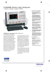
Download TLA7N3 Data Sheet

Transcript
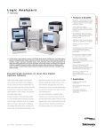
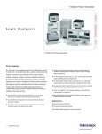
Tektronix Logic Analyzers
TLA7N4 Logic Analyzer Module
Features & Benefits
136 Channel Logic Analyzer with
up to 8 Mb Depth
MagniVu™ Acquisition Technology
Provides 2 GHz (500 ps) Timing
Resolution to Find Difficult
Problems Quickly
Up to 200 MHz State Acquisition
Analysis of Synchronous Digital
Circuits
Simultaneous State and Highspeed Timing Analysis Through
the Same Probe Pinpoints Elusive
Faults Without Double Probing
500 MHz Deep Timing Analysis
with Up to 8 Mb Per Channel
Glitch and Setup/Hold Triggering
and Display Finds and Displays
Elusive Hardware Problems
Transitional Storage Extends the
Signal Analysis Capture Time
Broad Processor and Bus Support
Breakthrough Solutions for Realtime Digital Systems Analysis
The TLA7N4 logic analyzer module
Today’s digital design engineers face
technology for providing high-speed
daily pressures to speed new products
sampling (up to 2 GHz) that dramatically
Applications
to the marketplace. The TLA7N4 logic
changes the way logic analyzers work
Hardware Debug and Verification
analyzer module answers the need with
and enables them to provide startling
breakthrough solutions for the entire
new measurement capabilities.
Processor/Bus Debug and
Verification
design team, providing the ability to
The TLA7N4 module offers high-speed
quickly monitor, capture and analyze
state synchronous capture and high-speed
real-time digital system operation in order
timing capture through the same set
to debug, verify, optimize and validate
of probes. It capitalizes on MagniVu
digital systems.
technology to offer 500 ps timing on all
Hardware developers, hardware/software
channels, glitch and setup/hold triggering
integrators and embedded software
and display, and timestamp that is
developers will appreciate the range of
always on at up to 500 ps resolution.
capabilities of the TLA7N4 logic analyzer
The TLA700 Series logic analyzer
module. Its broad feature set includes
modules are ideal for timing analysis,
capturing and correlating elusive hard-
multi-processor/bus applications and
ware and software faults; providing
embedded software analysis.
simultaneous state and high-speed timing
analysis through the same probe; using
deep state acquisition to find the cause
of complex problems; real-time, nonintrusive software execution tracing that
correlates to source code and to hardware events; and non-intrusive probing.
offers Tektronix’ breakthrough MagniVu
Full Range of General-Purpose
and High-density, Non-intrusive
Probes
Embedded Software Integration,
Debug and Verification
Tektronix Logic Analyzers
TLA7N4 Logic Analyzer Module
Characteristics
General
Number of Channels (all channels are acquired
including clocks) – TLA7N4: 136 channels (4 are
clock and 4 are qualifier channels).
Channel Grouping – No limit to number of groups or
number of channels per group (all channels can be
reused in multiple groups).
TLA700 Module “Merging” – Three modules can
be “merged” to make up to a 408-Channel module.
Merged modules exhibit the same depth as the
lesser of the three individual modules.
Word/range/setup-and-hold/glitch/transition
recognizers span all three modules. Only one set
of clock connections is required.
Time Stamp – 50-Bit at 500 ps resolution
(6.5 day range).
Clocking/Acquisition Modes – Internal, internal
2X, external. 2 GHz MagniVu™ high-speed timing
is available simultaneous with all modes.
Number of Mainframe Slots Required per
TLA700 Module – 2.
2
Input Characteristics
(with P6417, P6418, P6419
or P6434 probes)
State Acquisition Characteristics
(with P6417, P6418, P6419
or P6434 probes)
Capacitive Loading –
<0.7 pF data and clock (P6419).
1.4 pF typical data; 2 pF typical clock (P6418).
2 pF typical data and clock (P6417 and P6434).
Threshold Selection Range – From +5.0 V to
–2.0 V in 50 mV increments.
Threshold Selection Channel Granularity –
Separate selection for clock (1) and data (16) for
each 17-Channel probe connector.
Threshold Accuracy (including probe) –
±100 mV.
Input Voltage Range – Operating: 6.5 Vp-p centered
around the programmed threshold.
Non-destructive: ±15 V.
Minimum Input Signal Swing –
250 mV or 25% of signal swing, whichever is
greater (P6417, P6418 and P6419).
300 mV or 25% of signal swing (P6434).
Input Signal Minimum Slew Rate –
200 mV/ns typical.
State Clock Rate – 100 MHz standard,
200 MHz optional.
State Data Rate (half/full channels) –
400/200 Mb/s, typical. Requires 200 MHz
state option.
State Memory Depth with Timestamps – 64 Kb,
256 Kb, 1 Mb, or 4 Mb per channel.
Setup-and-Hold Time Selection Range – From
8.5 ns before to 7.0 ns after clock edge.
Setup-and-Hold Window – 2 ns typical.
Minimum Clock Pulse Width – 2 ns.
Active Clock Edge Separation – 5 ns.
Demux Channel Selection – Channels can be
demultiplexed to other channels through user
interface with 8-Channel granularity.
Logic Analyzers • www.tektronix.com/logic_analyzers
Tektronix Logic Analyzers
TLA7N4 Logic Analyzer Module
Timing Acquisition Characteristics
(with P6417, P6418, P6419
or P6434 probes)
MagniVu Timing – 500 ps.
MagniVu Timing Memory Depth – 2 Kb (2048)
per channel.
Deep Timing Resolution (half/full channels) –
2/4 ns to 50 ms.
Deep Timing Resolution with Glitch Storage
Enabled – 10 ns to 50 ms.
Deep Timing Memory Depth (half/full channels
with timestamps and with or without transitional storage) – 128/64 Kb, 512/256 Kb, 2/1 Mb,
8/4 Mb per channel.
Deep Timing Memory Depth with Glitch Storage
Enabled – Half of default main memory depth.
Channel-to-Channel Skew – <1 ns typical.
Minimum Recognizable Pulse Width
(single channel) – 2 ns.
Minimum Recognizable Glitch Width
(single channel) – 2 ns.
Minimum Recognizable Multi-channel Trigger
Event – Sample period +2 ns.
Trigger Characteristics
Independent Trigger States – 16.
Maximum Independent If/then Clauses per
State – 16.
Maximum Number of Events per If/then
Clause – 8.
Maximum Number of Actions per If/then
Clause – 8.
Maximum Number of Trigger Events – 18
(2 counter/timers plus any 16 other resources).
Number of Word Recognizers – 16.
Number of Range Recognizers – 4.
Number of Transition Recognizers – 1.
Number of Counter/Timers – 2.
Trigger Event Types – Word, group, channel,
transition, range, anything, counter value, timer
value, signal, glitch, setup-and-hold violation.
Trigger Action Types – Trigger module, trigger all,
store, don’t store, start store, stop store, increment
counter, reset counter, start timer, stop timer, reset
timer, goto state, set/clear signal, do nothing.
Trigger Sequence Rate – DC to 250 MHz (4 ns).
Counter/Timer Range – 51 Bits each (>100 days
at 4 ns).
Counter Rate – DC to 250 MHz (4 ns).
Timer Clock Rate – 250 MHz (4 ns).
Counter/Timer Latency – None (can be tested or
reset immediately after starting).
Range Recognizers – Double bounded (can be as
wide as any group, must be grouped according to
specified order of significance).
Setup-and-Hold Violation Recognizer Setup Time
Range – From 8 ns before to 7 ns after clock edge
in 0.5 ns increments.
Setup-and-Hold Violation Recognizer Hold Time
Range – From 7 ns before to 8 ns after clock edge
in 0.5 ns increments.
Trigger Position – Any data sample.
MagniVu Trigger Position – MagniVu data is
centered around the module trigger.
Storage Control (data qualification) – Global
(conditional), by state (start/stop), by trigger action or
transitional.
Storage Window Granularity – Single sample or
block-of-31 samples before and after.
Safety – CSA C22.2 No. 1010.1, EN61010-1,
IEC61010-1, UL 3111-1
Physical Characteristics
Dimensions
Height
Width
Depth
Weight
Net (without probes)
Shipping (typical)
mm
262
61
381
kg
3.1
6.3
in.
10.3
2.4
15
lb.
6.7
13.7
Logic Analyzers • www.tektronix.com/logic_analyzers
3
Tektronix Logic Analyzers
TLA7N4 Logic Analyzer Module
Ordering Information
TLA7N4 Logic Analyzer Module
Includes: Probe retainer bracket, probe manual,
certificate of calibration, one-year warranty
(return to Tektronix) and user manual.
Probes must be ordered separately – Order any
combination and quantity of probes by ordering the
P6417, P6418, P6419 or P6434 individually.
TLA7N4 – 136-Channel Logic Analyzer module,
2 GHz timing, 100 MHz state, 64 Kb depth. Options
for up to 4 Mb depth and/or 200 MHz state.
P6418.
P6418.
Quantity of Probes to Order
Per Option
Probe
TLA7N4
P6418
P6418 Probes
8
P6434 Probes
4
Part Number
P6417 Probes
8
334-9979-00
1 sheet of probe labels (not installed)
P6419 Probes
8
196-3476-00
1 each – 8-Channel leadset (barrel connectors
support 0.100" and 2 mm spacing)
Black
196-3479-00
1 each – 1-Channel leadset (barrel connectors
support 0.100" and 2 mm spacing)
Black
196-3477-00
(Optional) 1 each – 8-Channel reduced
bias voltage leadset (barrel connectors
support 0.100" and 2 mm spacing)
White
196-3478-00
(Optional) 1 each – 1-Channel reduced
bias voltage leadset (barrel connectors
support 0.100" and 2 mm spacing)
White
SMG50
20 each – SMT KlipChip™ grabber tips
Logic Analyzer Module Options
(Base configuration is 64 K depth at 100 MHz state.)
Opt. 1S – Increase to 256 K depth at 100 MHz state.
Opt. 2S – Increase to 1 M depth at 100 MHz state.
Opt. 3S – Increase to 4 M depth at 100 MHz state.
Opt. 4S – Increase to 64 K depth at 200 MHz state.
Opt. 5S – Increase to 256 K depth at 200 MHz state.
Opt. 6S – Increase to 1 M depth at 200 MHz state.
Opt. 7S – Increase to 4 M depth at 200 MHz state.
TLA7N4 Service Manual and
Test Fixtures
TLA7N4 Logic Analyzer Performance Verification
and Adjustment Fixture (includes AC adapter;
requires local power cord) – Order 671-3599-00.
TLA7N4 Logic Analyzer Modules Service Manual
(includes Performance Verification and Adjustment
procedures) – Order 071-0864-01.
TLA700 Series Module
Upgrades
You can increase the memory depth and state
speed of most existing TLA700 Series logic
analyzer modules. You can also install a TLA7N4
logic analyzer module into an existing TLA714/
715/720/721/7XM mainframe. Please refer to the
TLA Family Upgrade Guide for further details.
013-0280-00
SMK4
071-0567-00
Logic Analyzer Module Probes
and Accessories
P6418 – The P6418 is a 17-Channel generalpurpose probe with leadsets and grabber tips for
use with: 1) probing individual test points within
your target system, either directly or with a test
clip, or 2) direct connection to legacy TLA family
processor/bus support probe adapters with
Logic Analyzer Probe
Selection Guidelines
For the TLA7N4 logic analyzer module, you have
the choice of four probe options.
4
Logic Analyzers • www.tektronix.com/logic_analyzers
Description
(Optional) one-to-two adapter
(Optional) micro KlipChip grabber tip
adapter, 4 each
P6417/P6418 Instruction Manual
8-Channel probe connectors. The P6418 works
with a wide range of industry-standard probing
accessories for flexible attachment to your target
system. This probe is recommended for most
general-purpose applications.
17-Channel general-purpose probe and
accessories – Order P6418.
P6418 Probe Cable Length – 1.9 m (6.25 ft.).
Tektronix Logic Analyzers
TLA7N4 Logic Analyzer Module
P6417
Part Number
P6417.
2 each – 8-Channel podlet holders (installed)
N/A
1 set of 17 podlet color coding bands (installed)
334-9239-00
1 sheet of probe labels (not installed)
196-3476-00
1 each – 8-Channel leadset (barrel connectors
support 0.100" and 2 mm spacing)
Black
196-3479-00
1 each – 1-Channel leadset (barrel connectors
support 0.100" and 2 mm spacing)
Black
196-3477-00
(Optional) 1 each – 8-Channel reduced
bias voltage leadset (barrel connectors
support 0.100" and 2 mm spacing)
White
196-3478-00
(Optional) 1 each – 1-Channel reduced
bias voltage leadset (barrel connectors
support 0.100" and 2 mm spacing)
White
SMG50
20 each – SMT KlipChip™ grabber tips
013-0280-00
P6417.
Description
N/A
SMK4
071-0567-00
(Optional) one-to-two adapter
(Optional) micro KlipChip grabber tip
adapter, 4 each
P6417/P6418 Instruction Manual
P6417 – The P6417 is a 17-Channel generalpurpose probe that is similar to the P6418 with
the additional capability of allowing you to separate
the 8-Channel podlet groups into individual channels for both maximum electrical performance
and maximum distance between adjacent channels.
This probe is recommended for those generalpurpose applications that require maximum flexibility.
17-Channel general-purpose probe and
accessories – Order P6417.
P6417 Probe Cable Length – 1.8 m (6 ft.).
Logic Analyzers • www.tektronix.com/logic_analyzers
5
Tektronix Logic Analyzers
TLA7N4 Logic Analyzer Module
P6419.
P6419 – The P6419 is a 17-channel high-density
compression probe, with single-ended clock and
data. This probe utilizes a connector-less probe
attach mechanism for quick and reliable connections
to your system under test. This probe is recommended for those applications that require higher
signal density or a connector-less probe attach.
17 channel High-density Compression Probe,
with Single-ended Clock and Data – Order P6419.
P6419 Probe Cable Length – 1.8 m (6 ft.).
P6434 – The P6434 is a lightweight probe with
quick connect/disconnect and a positive latching
mechanism to ensure a secure, reliable connection.
It is for use with: 1) applications where you have
designed in the AMP Mictor high-density connectors
into your target system or 2) direct connection to
newer TLA family processor/bus support probe
adapters with AMP Mictor 34-Channel probe
connectors. An optional low-profile adapter for lowclearance applications is also available. This probe
is recommended for all high-density applications.
34-Channel High-density Probe and Accessories –
Order P6434.
P6434 Probe Cable Length – 1.5 m (5 ft.).
P6434.
P6434.
P6419
Part Number
Description
020-2453-00
Nut bar (used on <0.093 in. thick PCB)
Bag of 2
020-2451-00
Elastomer Holder Assembly, Thin [black]
(used on <0.093 in. thick PCB)
Bag of 2
020-2452-00
Elastomer Holder Assembly, Thick [gray]
(used on >0.093 in. thick PCB)
Bag of 2
335-1007-00
Sheet of probe labels
020-2457-00
(Optional) Mictor-on-PCB to
Compression Adapter
020-2455-00
(Optional) Compression-on-PCB to
Mictor Adapter, 17-Channel
P6434
Part Number
N/A
Description
1 sheet of probe labels (not installed)
105-1088-00
1 latch housing assembly, edge-mount
105-1089-00
1 latch housing assembly, vertical
070-9793-02
P6434 Instruction Manual
131-6134-01
(Optional) 1 each – AMP mictor connector,
surface-mount
020-2228-00
(Optional) 21 each – AMP mictor connector,
surface-mount
34-Channel Low-profile Adapter for P6434 – Order P6434 Opt. 01.
Part Number
Description
010-0612-00
6
Logic Analyzers • www.tektronix.com/logic_analyzers
(Optional) low-profile leadset for P6434
Tektronix Logic Analyzers
TLA7N4 Logic Analyzer Module
UPIK3M.
P6417 to 3M Type 3592, 2x10, 0.1 in. Adapter –
Order UPIK3M (5 each).
Order 671-2508-00 (1 each).
34-Channel Probe Interface Kit with Barrel
Connectors – Order 020-2199-00.
34-Channel Probe Interface Kit with mini-PV
Connectors – Order 020-3000-00.
Differential-to-single-Ended
Converters
Each podlet converts 8 input differential pairs to a
single-ended output for use with the TLA Logic
Analyzer. They draw their power from separate
wires connected to the system under test. The
units are shipped without any input termination
connected and a supply of 100 Ω termination
resistors for use and installation by the user,
if desired. The units are shipped without input
leadsets. Leadsets are also available.
Differential ECL/PECL
to Single-ended ECL
Converter Pod
Each channel is converted via an ON
Semiconductor MC10E416 buffer which will
support speeds as high as 800 MHz. The inputs
have provisions for differential and/or parallel
termination. The input power is provided via two
leads that are connected to a lower voltage and a
higher voltage, each DC-isolated from the output,
allowing operation in both ECL and PECL systems.
Differential LVDS/TTL
to Single-ended TTL
Converter Pod
Each channel is converted via a National
Semiconductor DS90LV032A receiver supporting
data rates in excess of 400 Mbps (200 MHz).
The inputs have provisions for differential terminations and have resistor-diode input protection from
over voltage.
For information or ordering, please contact:
Dragonfly Software Development
4905 SW Griffith Drive, Suite 100
Beaverton, OR 97005-8724
(503) 643-3800 phone
(503) 626-9653 fax
[email protected]
TLA7N4 Service Options
Opt. C3 – Calibration Service 3 Years.
Opt. C5 – Calibration Service 5 Years.
Opt. D1 – Calibration Data Report.
Opt. D3 – Calibration Data Report 3 Years
(with Opt. C3).
Opt. D5 – Calibration Data Report 5 Years
(with Opt. C5).
Opt. R3 – Repair Service 3 Years.
Opt. R5 – Repair Service 5 Years.
Opt. IN – Product Installation Service.
Differential-to-single-ended converter pods.
Logic Analyzers • www.tektronix.com/logic_analyzers
7
Tektronix Logic Analyzers
Contact Tektronix:
ASEAN / Australasia / Pakistan (65) 6356 3900
TLA7N4 Logic Analyzer Module
Austria +43 2236 8092 262
Belgium +32 (2) 715 89 70
Brazil & South America 55 (11) 3741-8360
Canada 1 (800) 661-5625
Central Europe & Greece +43 2236 8092 301
Denmark +45 44 850 700
Finland +358 (9) 4783 400
France & North Africa +33 (0) 1 69 86 80 34
Germany +49 (221) 94 77 400
Hong Kong (852) 2585-6688
India (91) 80-22275577
Italy +39 (02) 25086 1
Japan 81(3)6714-3010
Mexico, Central America & Caribbean 52 (55) 56666-333
The Netherlands +31 (0) 23 569 5555
Norway +47 22 07 07 00
People’s Republic of China 86 (10) 6235 1230
Poland +48 (0) 22 521 53 40
Republic of Korea 82 (2) 528-5299
Russia, CIS & The Baltics +358 (9) 4783 400
South Africa +27 11 254 8360
Spain (+34) 901 988 054
Sweden +46 8 477 6503/4
Taiwan 886 (2) 2722-9622
United Kingdom & Eire +44 (0) 1344 392400
USA 1 (800) 426-2200
USA (Export Sales) 1 (503) 627-1916
For other areas contact Tektronix, Inc. at: 1 (503) 627-7111
Last Update August 13, 2004
Our most up-to-date product information is available at:
www.tektronix.com
Product(s) are manufactured
in ISO registered facilities.
Copyright © 2004, Tektronix, Inc. All rights reserved. Tektronix products are
covered by U.S. and foreign patents, issued and pending. Information in this publication supersedes that in all previously published material. Specification and price
change privileges reserved. TEKTRONIX and TEK are registered trademarks of
Tektronix, Inc. All other trade names referenced are the service marks, trademarks or registered trademarks of their respective companies.
09/04
HB/WWW
52W-18099-1