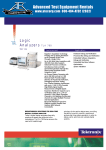
1
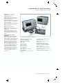
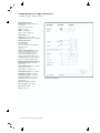
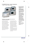
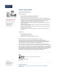
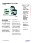
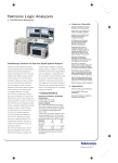
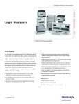
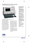
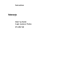
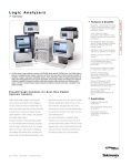
TLA5000 Series Logic Analyzers
TLA5201 • TLA5202 • TLA5203 • TLA5204
Features & Benefits
500 ps (2 GHz)/32 Mb Deep
Memory Timing to Capture
Intermittent Events Over a
Wide Time Window
125 ps-resolution MagniVu™
Timing Simultaneous with
State or Deep Memory Timing
Acquisition to Find Elusive
Timing Problems Quickly,
Without Double Probing
Glitch and Setup/hold
Violation Triggering and
Display to Find and Display
Elusive Hardware Problems
235 MHz State Acquisition
Provides Analysis of
High-speed Synchronous
Digital Circuits
iView™ Time-correlated Digitalanalog View to Clearly See
How Analog Anomalies are
Affecting Your Digital Signals
34/68/102/136 Channel
Configurations Offer Flexible
Solutions to Fit Any Budget
TLA5000 Series logic analyzers combine debug
power with simplicity and affordability
The affordable TLA5000 Series logic analyzers make high-speed timing resolution,
fast state acquisition, deep memory, and
sophisticated triggering available to any
digital designer who needs to identify initialization failures, operation crashes and
intermittent operation. For first-time as well
as experienced logic analyzer users, the
TLA5000 Series is ideal for single-bus timing
and state analysis. An intuitive user interface,
familiar Windows-based desktop and
OpenChoice® networking and analysis
features make the TLA5000 Series logic
analyzers easy to network into your
design environment.
1
Logic Analyzers • www.tektronix.com/logic_analyzers
500 ps timing resolution and 32 Mb
memory depth with simultaneous 125 ps
MagniVu timing resolution within each
acquisition means you can measure digital
signal timing on increasingly faster signals
with confidence. With MagniVu timing
resolution, find difficult problems such
as digital logic errors, glitches, setup/hold
violations, and crosstalk quickly. Use
setup/hold violation triggering and display
to validate setup/hold performance of
digital devices.
Today, most designs can have both digital
and analog anomalies. With iView timecorrelated digital-analog view, you’ll clearly
see how analog anomalies are affecting
your digital signals—right on your logic
analyzer display.
Applications
Digital Hardware Verification
and Debug
Monitoring and
Measurement of Digital
Hardware Performance
Single Microprocessor or
Bus Debug
TLA5000 Series Logic Analyzers
TLA5201 • TLA5202 • TLA5203 • TLA5204
Characteristics
General
Number of Channels –
(all channels are acquired including clocks).
TLA5201: 34 channels (2 are clock channels).
TLA5202: 68 channels (4 are clock channels).
TLA5203: 102 channels (4 are clock and 2 are
qualifier channels).
TLA5204: 136 channels (4 are clock and 4 are
qualifier channels).
Time Stamp – 51-Bits at 125 ps resolution
(3.25 days duration).
Clocking/Acquisition Modes –
Internal, internal 2X, internal 4X, external 2X, source
synchronous. 125 ps (8 GHz) MagniVu™ high-speed
timing is available simultaneous with all modes.
Input Characteristics
(with P6417, P6418, P6419
or P6434 probes)
Capacitive Loading –
<0.7 pF typical data/clock (P6419).
1.4 pF typical data; 2 pF typical clock (P6418).
2 pF typical data/clock (P6417, P6434).
Threshold Selection Range –
From –2.0 V to +4.5 V in 5 mV increments.
Threshold presets include TTL (1.5 V), CMOS
(1.65 V), ECL (–1.3 V), PECL (3.7 V), LVPECL (2.0 V),
LVCMOS 1.5 V (0.75 V), LVCMOS 1.8 V (0.9 V),
LVCMOS 2.5 V (1.25 V), LVCMOS 3.3 V (1.65 V),
LVDS (0 V), and user defined.
State Acquisition
Characteristics (with
P6417, P6418, P6419
or P6434 probes)
Maximum State Data Rate – 470 Mb/s.
Minimum Recognizable Pulse/Glitch Width
(single channel) – 1 ns (P6417, P6418, P6419).
1.25 ns (P6434).
State Memory Depth with Timestamps (half/full
channels) – 1 Mb/512 Kb , 4/2 Mb , 16/8 Mb.
Minimum Detectable Setup/Hold Violation –
250 ps.
Setup-and-Hold Time Selection Range –
16 ns range that may be shifted towards the setup
region by 0 ns [+8, –8] ns, 4 ns [+12, –4] ns, or
8 ns [+16, 0] ns.
Minimum Recognizable Multi-channel Trigger
Event – Sample period + channel-to-channel skew.
Maximum State Clock Rate – 235 MHz.
Setup-and-Hold Window – All Channels:
1.5 ns typical.
Minimum Clock Pulse Width –
1.5 ns (P6434).
1.25 ns (P6417, P6418, P6419).
Demux Channel Selection – Channels can be
demultiplexed to other channels through user
interface with 8 channel granularity.
Timing Acquisition
Characteristics (with
P6417, P6418, P6419
or P6434 probes)
MagniVu Timing –
125 ps (8 GHz).
Storage rate adjustable to 250 ps, 500 ps,
1 ns, and 2 ns.
MagniVu Timing Memory Depth –
16 Kb per channel, with adjustable trigger position.
Threshold Selection Channel Granularity –
Separate selection for each of the clock/qualifier
channels and one per group of 16 data channels.
Deep Memory Timing Resolution
(quarter/half/full channels) – 500 ps/1 ns/2 ns
to 50 ms.
Threshold Accuracy (including probe) – ±(100 mV).
Deep Memory Timing Memory Depth
(quarter/half/full channels with timestamps
and with or without transitional storage) –
2 Mb/1 Mb/512 Kb, 8/4/2 Mb, 32/16/8 Mb
per channel.
Input Voltage Range –
Operating: –2.5 V to 5.0 V.
Nondestructive: ±15 V.
Minimum Input Signal Swing –
±250 mV (P6417, P6418, P6419).
±300 mV (P6434).
Input Signal Minimum Slew Rate –
200 mV/ns typical.
2
Logic Analyzers • www.tektronix.com/logic_analyzers
Channel-to-Channel Skew –
1 ns.
900 ps typical.
Deep Memory Timing Memory Depth with
Glitch Storage Enabled – Half of default main
memory depth.
Trigger Characteristics
Independent Trigger States – 16.
Maximum Independent If/then Clauses
per State – 16.
Maximum Number of Events per If/Then
Clause – 8.
Maximum Number of Actions per If/Then
Clause – 8.
Maximum Number of Trigger Events – 18
(2 counter/timers plus any 16 other resources).
Number of Word Recognizers – 16.
Number of Transition Recognizers – 16.
Number of Range Recognizers – 4.
Number of Counter/Timers – 2.
Trigger Event Types – Word, group, channel,
transition, range, anything, counter value, timer
value, signal, glitch, setup-and-hold violation,
snapshot.
Trigger Action Types – Trigger main, trigger
MagniVu, store, don’t store, start store, stop store,
increment counter, decrement counter, reset counter,
start timer, stop timer, reset timer, snapshot current
sample, goto state, set/clear signal, do nothing.
Trigger Sequence Rate – DC to 500 MHz (2 ns).
Counter/Timer Range – 51 Bits each (>50 days
at 2 ns).
TLA5000 Series Logic Analyzers
TLA5201 • TLA5202 • TLA5203 • TLA5204
Counter Rate – DC to 500 MHz (2 ns).
Timer Clock Rate – 500 MHz (2 ns).
Counter/Timer Latency – 2 ns.
Range Recognizers – Double bounded (can be as
wide as any group, must be grouped according to
specified order of significance).
Setup-and-Hold Violation Recognizer Setup Time
Range – From 8 ns before to 7.5 ns after clock
edge in 125 ps increments.
Setup-and-Hold Violation Recognizer Hold Time
Range – From 7.5 ns before to 8 ns after clock
edge in 125 ps increments.
Trigger Position – Any data sample.
MagniVu™ Trigger Position – MagniVu position can
be set from 0% to 60% centered around the
MagniVu trigger.
Storage Control (data qualification) – Global
(conditional), by state (start/stop), block, by trigger
action, or transitional. Force main prefill selection
available.
iView™ (Integrated View)
Capability
TDS oscilloscope configuration requirements –
The iView™ cable does not connect fully to the
TDS1000/2000 Series oscilloscopes without a GPIB
extender. Tektronix recommends a standard GPIB
cable as an extender, or order a cable extender
(National Instruments part number 181638-1).
TDS2CMAX Communications Extension Module
required for iView capability on any TDS1000/2000
Series. TDS3GM GPIB/RS232 Interface Module
required for iView capability on any TDS3000 Series.
TDS3GV GPIB/RS232/VGA Interface Module
required for iView capability on any TDS3000B
Series. If using TLA7Axx iConnect with a TDS6404,
TDS6604, TDS7154, TDS7404, or CSA7154
oscilloscope, four TCA-BNC connectors are required
to be compatible with BNC cable from the
TLA7Axx module.
TLA5000 Series with TDS5000 Series Oscilloscope.
Number of TDS oscilloscopes that can be
connected to a TLA system – 1.
TDS Connections – GPIB, Trigger In, Trigger Out,
Clock In (when available).
External Oscilloscopes Supported –
TDS1000 Series.
TDS2000 Series.
TDS3000/3000B Series.
TDS5000/5000B Series.
TDS6000/6000B Series.
TDS7000/7000B Series.
CSA7000/7000B Series.
TDS684C, TDS694C.
TDS754C, TDS784C, TDS724D, TDS754D,
TDS784D, TDS794D.
Setup – iView external oscilloscope wizard
automates setup.
Data Correlation – After TDS oscilloscope
acquisition is complete, data is automatically
transferred to the TLA and time correlated with
the TLA acquisition data.
Deskew – TDS and TLA data is automatically
deskewed and time correlated when using the iView
external oscilloscope cable.
iView External Oscilloscope Cable Length – 2 m.
TLA Connections – USB, Trigger In, Trigger Out,
Clock Out.
Logic Analyzers • www.tektronix.com/logic_analyzers
3
TLA5000 Series Logic Analyzers
TLA5201 • TLA5202 • TLA5203 • TLA5204
PC Characteristics
Operating System – Microsoft Windows 2000
Professional SP3.
Processor – Intel Celeron 2.0 GHz.
Chipset – Intel 845GV.
DRAM – 512 MB SDRAM.
Sound – 16-Bit I/O and Mic In port.
Hard Disk Drive – 80 GB.
CD-ROM – Internal 24/10/24 CD-RW.
Floppy Disk Drive – Built-in 3.5 in. 1.44 MB drive.
Integral Controls
Front-Panel Display –
Size: 10.4 in. diagonal.
Type: Active-matrix color TFT LCD with backlight.
Resolution: 1024x768.
Colors: 256 K.
Simultaneous Display Capability – The frontpanel and secondary displays can be operated
simultaneously using the same resolution.
The secondary external display can be used
simultaneously using an independent resolution.
Front-panel Controls – Special function knobs for
instrument control and mini-QWERTY keypad.
External Peripheral Interfaces
External Display Port Type – Female DB15
SVGA connector.
External Display Resolution – Up to 1600x1200
non-interlaced at 16.8 M colors.
LAN Port Type – 10/100Base-T, RJ-45.
External Keyboard Port Type – PS2 mini-DIN.
External Mouse Port Type – PS2 mini-DIN.
Parallel Interface Port Type – Female DB25.
Parallel Interface Modes – Centronics mode,
EPP (Extended Parallel Port), ECP (Microsoft
high-speed mode).
Serial Interface Port Type – Male DB9.
Audio Out Port Type – Stereo minijack.
Mic In Port Type – Minijack.
USB Port – Two USB 2.0.
4
Logic Analyzers • www.tektronix.com/logic_analyzers
TLA5000 Logic Analyzer I/O.
TLA5000 Series Logic Analyzers
TLA5201 • TLA5202 • TLA5203 • TLA5204
Symbolic Support
Number of Symbols/Ranges – Unlimited (limited
only by amount of virtual memory available on TLA).
Object File Formats Supported –
IEEE695
OMF 51, OMF 86, OMF 166, OMF 286,
OMF 386
COFF
Elf/Dwarf 1 and 2
Elf/Stabs
TSF (if your software development tools
do not generate output in one of the above
formats, TSF or the Tektronix symbol file,
a generic ASCII file format is supported.
The generic ASCII file format is documented
in the TLA User Manual). If a format is not
listed, please contact your local Tektronix
representative
External Instrumentation
Interfaces
System Trigger Output – Asserted whenever a
system trigger occurs (TTL-compatible output,
back-terminated into 50 Ω). BNC type connector.
System Trigger Input – Forces a system trigger
(triggers all modules) when asserted (TTL-compatible,
edge-sensitive, falling-edge latched). BNC type
connector.
External Signal Output – Can be used to drive
external circuitry from a module’s trigger mechanism
(TTL-compatible output, back-terminated into 50 Ω).
BNC type connector.
External Signal Input – Can be used to provide an
external signal to arm or trigger any or all modules
(TTL-compatible, level-sensitive). BNC type connector.
Power
Voltage range/frequency – 90-240 VAC at
47 to 63 Hz.
Input current – 5 A maximum at 90 VAC.
Power consumption – 300 W maximum.
Physical Characteristics
TLA5000
Dimensions
Height
Width
Depth
Weight
Net (w/o probes)
Shipping (typical)
mm
285
438
288
kg
12
18.5
in.
11.2
17.5
11.35
lb.
26
41
Environmental
Temperature –
Operating: +5 ºC to +50 ºC.
Nonoperating: –20 ºC to +60 ºC.
Humidity –
20% to 80%.
Operating: 20% to 80% relative humidity (29 ºC
maximum wet bulb temperature).
Nonoperating: 8% to 80% (29 ºC maximum
wet bulb temperature).
Altitude – Operating: –1,000 ft. to 10,000 ft.
(–305 meters to 3,050 meters).
Safety – UL3111-1, CSA1010.1, EN61010-1,
IEC61010-1.
Logic Analyzers • www.tektronix.com/logic_analyzers
5
TLA5000 Series Logic Analyzers
TLA5201 • TLA5202 • TLA5203 • TLA5204
Ordering Information
TLA5201
34 Channel, 2 GHz Deep Memory Timing with
125 ps MagniVu™ Acquisition, 235 MHz State,
512 Kb Logic Analyzer.
TLA5202
68 Channel, 2 GHz Deep Memory Timing with
125 ps MagniVu Acquisition, 235 MHz State,
512 Kb Logic Analyzer.
TLA5203
102 Channel, 2 GHz Deep Memory Timing with
125 ps MagniVu Acquisition, 235 MHz State,
512 Kb Logic Analyzer.
TLA5204
136 Channel, 2 GHz Deep Memory Timing with
125 ps MagniVu Acquisition, 235 MHz State,
512 Kb Logic Analyzer.
All Include: Mini Keyboard (118-9402-00),
Optical Wheel Mouse (119-6936-00), Front Panel
Cover (200-4651-00), Probe Retainer Bracket
(407-4435-01), Accessory Pouch (016-1935-00),
Mouse Pad (016-1524-04), TLA5000 Series
Product Software CD (063-3487-02), TLA5000
Series Operating System Restore CD (063-3672-00),
TLA Documentation CD (063-3671-00), TLA5000
Quick Installation Reference (071-1302-00),
TLA V4.3 User Manual (071-1236-00), TLA5000
Installation Manual (071-1301-00), Certificate
of Traceable Calibration, Power Cord.
Please specify power cord and language options
when ordering.
Probes are sold separately.
6
Logic Analyzers • www.tektronix.com/logic_analyzers
Instrument Options
Service Options
Opt. 1C – Add iView™ external oscilloscope cable
kit (012-1614-01).
Opt. 7S – Increase to 2 Mb base memory depth
per channel.
Opt. 8S – Increase to 8 Mb base memory depth
per channel.
Opt. C3 – Calibration Service 3 Years.
Opt. C5 – Calibration Service 5 Years.
Opt. D1 – Calibration Data Report.
Opt. D3 – Calibration Data Report 3 Years
(with Option C3).
Opt. D5 – Calibration Data Report 5 Years
(with Option C5).
Opt. R3 – Repair Service 3 Years.
Opt. R5 – Repair Service 5 Years.
Recommended Accessories
Logic Analyzer Cart – LACART, K4000.
Logic Analyzer Cart Mounting Bracket Kit –
(407-4996-00).
TLA5000 Rackmount Kit – (016-1887-00).
TLA5000 Wheeled Transport Case –
(016-1937-00).
TLA7QS Technical Reference Support Kit –
(020-2211-02).
TLA7QS Quickstart Training Manual –
(070-9717-05).
TLA5000 Service Manual – (071-1305-00).
International Power Plugs
A0 – North America power.
A1 – Universal EURO power.
A2 – United Kingdom power.
A3 – Australia power.
A4 – 240 V, North America power.
A5 – Switzerland power.
A6 – Japan power.
A10 – China power.
A99 – No power cord or AC adapter.
Software
TLA5000 Series Product Software CD –
063-3487-xx.
Language Options
Opt. L0 – English Manuals.
Opt. L10 – Russian Manuals.
Opt. L99 – No Manuals.
TLA5000 Series Logic Analyzers
TLA5201 • TLA5202 • TLA5203 • TLA5204
Logic Analyzer Probe Selection Guidelines
There is a flexible choice of logic analyzer probes available for use with TLA5000 logic analyzers.
Te k t r o n i x L o g i c A n a l y z e r P r o b e S e l e c t i o n G u i d e
P6417
Logic Analyzer Used
Recommended Use
Attachment to Target System
Probe Type
Logic Signals Supported
Probe Load AC/DC
P6418
P6419
P6434
TLA6xx Logic Analyzers
TLA520x Logic Analyzer Modules
TLA7Lx/Mx/Nx/ Px/Qx Logic Analyzer Modules
Recommended for most
general-purpose uses that
require maximum flexibility
Recommended for most
general-purpose uses
Recommended for applications Recommended for applications
requiring many channels
requiring many channels
to be quickly connected in a
to be quickly connected
small footprint
in a small footprint
Probe leadsets adapt to
industry standard interfaces;
leads spread over a wide area
Probe leadsets adapt to
industry standard interfaces
Connectorless “compression”
contact (Adapter for
Mictor connector available)
AMP Mictor 34 channel
connector (Adapter to use
P6434 with P6860/80
high-density compression
land footprint available)
General purpose,
17 channel passive probe
General purpose,
17 channel passive probe
High density,
17 channel passive probe
High density,
34 channel passive probe
AMP Mictor connector required
Single-ended Clock and Data
(Differential signal
adapters available)
Single-ended Clock and Data
(Differential signal
adapters available)
Single-ended Clock and Data
Single-ended Clock and Data
2 pF/ 20 kΩ to 2.2 V
(Low-voltage adapters
that work with low-voltage
signals are available)
2 pF/ 20 kΩ to 2.2 V
(Low-voltage adapters
that work with low-voltage
signals are available)
<0.7 pF/ 20 kΩ to ground
2 pF/ 20 kΩ to 2.2 V
Logic Analyzers • www.tektronix.com/logic_analyzers
7
TLA5000 Series Logic Analyzers
Contact Tektronix:
TLA5201 • TLA5202 • TLA5203 • TLA5204
ASEAN / Australasia / Pakistan (65) 6356 3900
Austria +43 2236 8092 262
Belgium +32 (2) 715 89 70
Brazil & South America 55 (11) 3741-8360
Canada 1 (800) 661-5625
Central Europe & Greece +43 2236 8092 301
Denmark +45 44 850 700
Finland +358 (9) 4783 400
France & North Africa +33 (0) 1 69 86 80 34
Germany +49 (221) 94 77 400
Hong Kong (852) 2585-6688
India (91) 80-22275577
Italy +39 (02) 25086 1
Japan 81 (3) 6714-3010
Mexico, Central America & Caribbean 52 (55) 56666-333
The Netherlands +31 (0) 23 569 5555
Norway +47 22 07 07 00
People’s Republic of China 86 (10) 6235 1230
Poland +48 (0) 22 521 53 40
Republic of Korea 82 (2) 528-5299
Russia, CIS & The Baltics +358 (9) 4783 400
South Africa +27 11 254 8360
Spain +34 (91) 372 6055
Sweden +46 8 477 6503/4
Taiwan 886 (2) 2722-9622
United Kingdom & Eire +44 (0) 1344 392400
USA 1 (800) 426-2200
USA (Export Sales) 1 (503) 627-1916
For other areas contact Tektronix, Inc. at: 1 (503) 627-7111
Last Update March 01, 2004
Our most up-to-date product information is available at:
www.tektronix.com
Product(s) are manufactured
in ISO registered facilities.
Product(s) complies with IEEE Standard 488.1-1987, RS-232-C, and with
Tektronix Standard Codes and Formats.
Copyright © 2004, Tektronix, Inc. All rights reserved. Tektronix products are covered
by U.S. and foreign patents, issued and pending. Information in this publication
supersedes that in all previously published material. Specification and price change
privileges reserved. TEKTRONIX and TEK are registered trademarks of Tektronix,
Inc. All other trade names referenced are the service marks, trademarks or registered trademarks of their respective companies.
05/04
8
Logic Analyzers • www.tektronix.com/logic_analyzers
HB/WOW
58W-16733-2