1
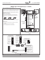
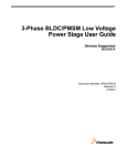
Powered by
VSD Series Quick Start Guide
Eaton’s Technology
November 2009
VSD Series Quick Start Guide
Open Drive
Bypass Drive
NEMA Type 12
General
IMPORTANT: This guide is intended to provide a quick reference to
the VSD Series drive’s Application Software features for start-up,
programming and service. It does not replace the need to thoroughly
read and understand the User Manual.
Upon receipt of the unit, verify that the catalog number and unit
options stated on the shipping container match those stated on
the order/purchase form.
Table of Contents
Description
Page
NEMA Type 1/12 Open Drives (1 – 250 HP) . . . . . . . . . . . . . .
2
NEMA Type 1 IntelliPass/IntelliDisconnect Drive . . . . . . . . .
5
Enclosed NEMA Type 12/3R . . . . . . . . . . . . . . . . . . . . . . . . . .
10
Appendix A — Main Control Board Wiring . . . . . . . . . . . . .
15
Appendix B — Interlock Damper Start Example
Using 4 – 20 mA Control Signal . . . . . . . . . . . . . . . . . . .
16
Appendix C — Interlock Damper Start Example
Using PID Duct Static Control Signal . . . . . . . . . . . . . . .
17
Appendix D — Bypass Wiring Diagram . . . . . . . . . . . . . . . .
18
Appendix E — Keypad Navigation . . . . . . . . . . . . . . . . . . . .
19
Appendix F — Main Menu Navigation . . . . . . . . . . . . . . . . .
20
Appendix G — Start-Up Wizard . . . . . . . . . . . . . . . . . . . . . . .
21
Appendix H — Static Checking . . . . . . . . . . . . . . . . . . . . . . .
25
Appendix I — Fault and Warning Codes . . . . . . . . . . . . . . . .
27
Technical Support Phone Numbers
Branch: 800-281-3792 (Option 1)
Third Party (ABCS/DIST): 800-445-4757 (Option 1)
Inspect the equipment upon delivery. Report any carton damage
to the carrier prior to accepting the delivery. Have this
information noted on the freight bill. Johnson Controls is not
responsible for damage incurred in shipping.
Unpacking
Remove all packing material from the unit. Be sure to remove all
packing material from lug location. Also, make sure no packing
material is left behind that would block the airflow to the fan.
Check the unit for any signs of shipping damage. If damage to
the product is found after unpacking, report it to the freight
company. Retain the packing materials for the carrier to review.
Storage
It is recommended that the unit be stored in its original shipping
box/crate until it is to be installed.
The unit should be stored in a location where:
•
•
•
•
The ambient temperature is between -40°F and 158°F
(-40°C and 70°C)
The relative humidity is between 0% and 95%,
non-condensing
The environment is dry, clean, and non-corrosive
The unit will not be subjected to high shock or vibration
conditions
Mandatory Ground Wiring (See Appendix D on Page 18)
Be sure to pull low impendance ground wiring from customer
power to drive and ground wire from drive to motor.
Utility
LIT-1201858
NEMA Type 3R
For more information visit: www.johnsoncontrols.com
Drive
Motor Ground
(Inside Motor Conduit Box)
1
VSD Series Quick Start Guide
Powered by
Eaton’s Technology
November 2009
NEMA Type 1/12 Open Drives (1 – 250 HP)
Table 1: Control Wiring Instructions
Mounting Drive
W1
W2
1. Mount Drive
(See Table below for dimensions.)
R2
D1
R1
D2
H1
H2
H3
D3
R2
Knockouts
Figure 1:
VSD Series Open Drive Dimensions
Frame
Size
Voltage
FR4
230V
3/4 – 3
480V
1–5
230V
5 – 7-1/2
480V
7-1/2 – 15
230V
10 – 15
480V
20 – 30
575V
2 – 25
230V
20 – 30
480V
40 – 60
575V
30 – 40
FR5
FR6
FR7
FR8
FR9
FR10
hp (VT)
480V
75 – 125
575V
50 – 75
480V
150 – 200
575V
100 – 150
480V
250 – 350
575V
200 – 300
Approximate Dimensions in Inches (mm)
Weight
Lbs. (kg)
H1
H2
H3
D1
D2
D3
W1
W2
R1 dia.
R2 dia.
12.9
(327)
12.3
(313)
11.5
(292)
7.5
(190)
2.5
(64)
5.0
(126)
5.0
(128)
3.9
(100)
.5
(13)
.3
(7)
11
(5)
16.5
(419)
16.0
(406)
15.4
(391)
8.4
(214)
2.7
(68)
5.8
(148)
5.7
(144)
3.9
(100)
.5
(13)
.3
(7)
17.9
(8.1)
22.0
(558)
21.3
(541)
20.4
(519)
9.3
(237)
2.7
(68)
6.7
(171)
7.7
(195)
5.8
(148)
.7
(18)
.4
(9)
40.8
(18.5)
24.8
(630)
24.2
(614)
23.3
(591)
10.1
(257)
2.7
(68)
7.5
(189)
9.3
(237)
7.5
(190)
.7
(18)
.4
(9)
77.2
(35)
29.7
(755)
28.8
(732)
28.4
(721)
11.3
(288)
1.3
(34)
11.0
(279)
11.2
(285)
10.0
(255)
.7
(18)
.4
(9)
127.8
(58)
45.3
(1150)
44.1
(1120)
—
14.3
(362)
5.4
(137)
8.8
(224)
18.9
(480)
15.7
(400)
.7
(18)
.4
(9)
321.9
(146)
44
(1120)
33.5
(850)
—
23.6
(600)
NA
NA
23.6
(600)
16.7
(425)
.9
(23)
.47
(12)
550.7
(250)
Power Wiring
Notice
Do not discard the plastic bag containing the wiring plate.
2. Remove the bottom cover by rotating the cover toward
you on the base hinges, then lifting the cover away from
the base.
Power Wiring
3. Locate the plastic bag shipped with the drive containing
the wiring plate, and remove the wiring plate.
2
For more information visit: www.johnsoncontrols.com
LIT-1201858
Powered by
Eaton’s Technology
VSD Series Quick Start Guide
November 2009
NEMA Type 1/12 Open Drives (1 – 250 HP)
Table 1: Control Wiring Instructions (continued)
Power Wiring
4. If conduit is being used, attach the wiring plate to it.
5. Pass the motor and input power wires/cables through the
holes of the wiring plate.
6. If shielded cable is used, connect the shields of the input
line power cable and the motor cable to the motor and
power ground terminals of the VSD Series drive.
Power Wiring/Grounding
7. Wire power terminals, motor terminals, and grounding
terminals per diagram. Power and Motor leads must be in
separate conduit.
Note: Do not wire motor loads to B- B+ R-. This will cause
damage.
GROUND WIRING
•
•
•
•
Run motor cables in separate conduit.
DO NOT RUN CONTROL WIRES in same conduit
Cables sized per NEC.
Provide low impedance ground between drive and
motor.
Utility
Drive
Motor Ground
(Inside Motor Conduit Box)
IMPORTANT: Improper grounding could result in damage to the
motor and/or drive and could void warranty
Control Wiring
8. Wire the control terminals following the details for the
specific option boards shown on the following pages.
Note: For ease of access, the option board terminal blocks can
be unplugged for wiring.
Note: If using conduit or Seal Tite for control wiring for Frame
4, you must order NEMA Type 12 kit.
LIT-1201858
For more information visit: www.johnsoncontrols.com
3
VSD Series Quick Start Guide
Powered by
Eaton’s Technology
November 2009
NEMA Type 1/12 Open Drives (1 – 250 HP)
Table 1: Control Wiring Instructions (continued)
Control Wiring
Incoming Power
9. Wire control to the OPTA9 Control Board and OPTA2.
Note: Drive default is programmed for Damper Interlock.
Note: Option Boards OPTC2 (N2/XT/SA Bus) and OPTC4
(LonWorks) are optional.
Optional
CB
Mandatory Ground Wiring
Be sure to pull low impendance ground wiring from
customer power to drive and ground wire from drive
to motor.
Utility
Drive
Motor Ground
(Inside Motor Conduit Box)
Note: Must pull
dedicated
ground wire
to drive
and motor.
I/O Connection
• Run 110 Vac and 24 Vdc Control wiring in separate
conduit.
• Communication wire to be shielded.
• RS-232 Keypad cable less than 20 feet.
1
2
3
4
5
6
7
8
9
10
11
12
13
14
15
16
17
18
19
20
+1DV
Vin+
GND
Lin+
Lin–
24Vout
GND
DIN1
DIN2
DIN3
CMA
24Vout
GND
DIN4
DIN5
DIN6
CMB
Lout+
Lout–
DO1
Reference Output
X1
A
B
C
D
Analog Input Voltage
(Range 0-10V DC)
I/O Ground
Analog Input Current
(Range 4-20mA)
X2
A
B
C
D
Control Voltage Output
X3
I/O Ground
Start/Stop
External Fault
Run Permisive Damper Interlock
DIN1-DIN3 Common
Control Voltage Output
I/O Ground
Speed Select 1
Fire Mode
Bypass Overload Fault
DIN4-DIN6 Common
X6
A
Output Frequency
B
C
Analog Output
D
Digital Output Ready
Note:
See Figure 3
for Dip X1, X2,
X3, X6 Switch
settings.
Note: Optional Communication Cards can be
supplied with the Drive or as a Field Option.
Figure 2:
X1 Jumper Setting
Analog Input 1 (AI1)
ABC D
0 to 10V*
Voltage Input
0 to 20 mA
Current Input
ABC D
0 to 10V
ABC D
(Differential)
Voltage Input
-10 to 10V
Voltage Input
ABC D
X2 Jumper Setting
Analog Input 2 (AI2)
0 to 20 mA* A B C D
Current Input
ABC D
0 to 10V
Voltage Input
X6 Jumper Setting
Analog Output 1 (A01)
0 to 10V
ABC D
(Differential)
Voltage Input
ABC D
0 to 20 mA*
Current Output
ABC D
-10 to 10V
Voltage Input
ABC D
0 to 10V
Voltage Output
ABC D ABC D
X1
X2
ABC D
X6
X3 Jumper Setting
CMA and CMB Grounding
CMB Connected to Ground*
CMA Connected to Ground
CMB Isolated from Ground
CMA Isolated from Ground
X3
CMB and CMA Internally
Connected and Isolated
from Ground
* Designates Default Jumper Settings
Figure 3: Option Board A9 Location and Settings
Start-Up Wizard
4
See Appendix G.
For more information visit: www.johnsoncontrols.com
LIT-1201858
Powered by
VSD Series Quick Start Guide
Eaton’s Technology
November 2009
NEMA Type 1 IntelliPass/IntelliDisconnect Drive
Circuit Breaker Endplate
Circuit Breaker
Extension Bar
Circuit Breaker
24V DC Power Supply *
Ribbon
Cable Hinge
Optional 3rd Input Contactor *
Output & Bypass
Contactor*
Contactor Overload *
Manual/Auto Reset *
24V DC Motor Overload
Terminal Block *
Ground Studs
* IntelliPass only.
Drive Enclosure Endplate
(located at bottom)
Optional 3rd Contactor S1 Switch *
(provided for drive isolation)
Figure 4: Identification of NEMA Type 1 Components
Table 2: VSD Series NEMA Type 1 IntelliPass/IntelliDisconnect Drive
Dimensions
Drive
Horsepower (VT)
Frame
Size
Approximate
Dimensions in
Inches (mm)
Approx.
Weight
in lbs. (kg)
A
B
C
Distance
Between
Drives in
Inches (mm) D
208V, 1 – 3 hp
230V, 1 – 3 hp
480V, 1 – 7-1/2 hp
FR4
5.04
(128)
18.25
(464)
13.24
(336)
21 (9.5)
5.3 (134.6)
208V, 5 – 7-1/2 hp
230V, 5 – 10 hp
480V, 10 – 20 hp
FR5
5.50
(140)
23.25
(591)
13.24
(336)
35 (15.9)
5.7 (144.8)
208V, 10 – 20 hp
230V, 15 and 20 hp
480V, 25 – 40 hp
FR6
7.50
(191)
29.38
(746)
15.25
(387)
67 (30.4)
7.5 (190.5)
208V, 25 and 30 hp
230V, 25 and 30 hp
480V, 50 – 75 hp
FR7
9.10
(231)
37.53
(953)
15.25
(387)
108 (49.0)
9.0 (228.6)
If mounting two or more IntelliPass Drives next to each other, make sure to use the
proper spacing between the drives for hinged door operation.
Figure 5: VSD Series IntelliPass/IntelliDisconnect Drive Dimensions
LIT-1201858
For more information visit: www.johnsoncontrols.com
5
VSD Series Quick Start Guide
Powered by
Eaton’s Technology
November 2009
NEMA Type 1 IntelliPass/IntelliDisconnect Drive
Table 3: Bypass Power Wiring Instructions — NEMA Type 1
Mounting Drive
1. Mount drive per dimensions. (See Page 5.)
2. Verify that the main power source is removed upstream.
3. Using a flat-blade screwdriver, remove the four screws
securing the outer cover of the drive and remove the
cover.
4. Using the same screwdriver, remove the two center
screws securing the side cover.
5. Make sure there is adequate room, and open the hinged
side cover.
Outer Cover
Two Screws on
Side Cover
Power Wiring
6. Using a flat-blade screwdriver, remove the screws
securing the endplate at the bottom of the drive enclosure,
and remove the endplate.
7. Using a Greenlee conduit cutter (recommended), cut one
or more holes in the endplate, located at the bottom of the
drive’s enclosure, for the motor and power leads.
Bottom
Endplate
Note: If bringing the power leads in through the top of the
drive’s enclosure, go to step 8. If not, proceed to step 10.
Power Wiring
8. Using a flat-blade screwdriver, remove the screws
securing the endplate for the circuit breaker enclosure,
and remove the endplate.
9. Using a Greenlee conduit cutter (recommended), cut one
hole in the circuit breaker endplate for the power leads.
Power Wiring
10. Calibrate the circuit breaker amperage, so it is 1.25 times
the amperage on the motor nameplate, by turning the
red set screw located below the circuit breaker extension
bar. See the circuit breaker user’s manual supplied with
the drive.
11. Connect the incoming power leads to circuit breaker
terminals labeled L1, L2 and L3. Cables sized per NEC.
12. Using the torque wrench, tighten each terminal to the
torque value found in the appropriate user’s manual
supplied with the drive.
POWER WIRING
• Run cabling in separate metal conduit or wiring tray.
• DO NOT RUN CONTROL WIRING with incoming
Circuit Breaker
Endplate
Incoming
Power Leads
Circuit Breaker
Terminals
Circuit Breaker
Set Screw
Circuit Breaker
Extension Bar
power wiring.
• Provide low impedance ground connection to drive
chassis.
• DO NOT CONNECT to B+, B-, R terminals.
6
For more information visit: www.johnsoncontrols.com
LIT-1201858
Powered by
VSD Series Quick Start Guide
Eaton’s Technology
November 2009
NEMA Type 1 IntelliPass/IntelliDisconnect Drive
Table 3: Bypass Power Wiring Instructions — NEMA Type 1 (continued)
Motor Wiring
13. Use your first and second fingers and simultaneously
push down to release the two orange retaining clips (one
on each side of the 24V DC motor overload terminal
block).
14. If necessary, use a flat-blade screwdriver to carefully
remove the terminal block in a straight plane to avoid
damaging it.
Motor Wiring
15. Connect the motor leads to the motor overload terminals
labeled 1TA, 1TB and 1TC.
16. Using the appropriate metric Allen wrench (2.5 mm, 3 mm
or 4 mm), tighten each overload terminal per the
specifications in the contactor user’s manual.
MOTOR WIRING
Motor
Overload
Terminals
Motor
Leads
An SAE allen wrench will damage the terminals,
and the motor overload will need to be replaced
(not covered by warranty).
17. Using the torque wrench, tighten each terminal to the
torque value found in the appropriate user’s manual
supplied with the drive.
18. Reinsert the motor overload terminal block.
Grounding
19. Use a flat-blade screwdriver to connect the motor ground
wire to the ground stud (located at either the top or
bottom of the drive’s enclosure). (Mandatory) Ground
connection main power ground must be connected to
other ground screws.
Motor
Ground
Stud
GROUND WIRING
•
•
•
•
Run motor cables in separate conduit.
DO NOT RUN CONTROL WIRES in same conduit
Cables sized per NEC.
Provide low impedance ground between drive and
motor.
Utility
Drive
Motor Ground
(Inside Motor Conduit Box)
IMPORTANT: Improper grounding could result in damage to the
motor and/or drive and could void warranty
LIT-1201858
For more information visit: www.johnsoncontrols.com
7
VSD Series Quick Start Guide
Powered by
Eaton’s Technology
November 2009
NEMA Type 1 IntelliPass/IntelliDisconnect Drive
Table 3: Bypass Power Wiring Instructions — NEMA Type 1 (continued)
Setting Overload
Auto/Manual
Reset
20. Lift to open the cover on the motor overload, and use a
1/8" flat-blade screwdriver to set the overload amperage to
match the value on the motor nameplate.
21. Turn the auto/manual reset (factory default is manual) on
the motor overload 90° to the auto position.
Control Wiring
22. Use a flat-blade screwdriver to carefully remove the lowvoltage I/O terminal block.
23. Insert the incoming control leads into the terminal block.
Refer to the electrical schematic supplied with the drive.
24. Reinsert the I/O terminal block into the control board.
25. Verify that all other wires to the terminal block are
connected.
26. Terminate control wiring to the OPTA9 and OPTA2 board
(Terminals 1 – 26).
CONTROL WIRING
• Run 110 Vac and 24 Vdc control wiring in separate
conduit.
• Communication wire must be shielded.
• RS-232 keypad cable must be less then 25 feet.
Drive
Ground
Optional
Customer
Ground
Motor
Ground
Note: See Figure 3
for Dip X1, X2,
X3, X6 Switch
settings.
Optional
Drive
Ground
Start/Stop
Speed Select 1
Fire Mode
Bypass Overload Fault
Note: Optional COMM cards can be supplied
Note: with the drive or as a field option.
Figure 6: VSD Series IntelliPass with Three Contactors
8
For more information visit: www.johnsoncontrols.com
LIT-1201858
Powered by
VSD Series Quick Start Guide
Eaton’s Technology
November 2009
NEMA Type 1 IntelliPass/IntelliDisconnect Drive
able 3: Bypass Power Wiring Instructions — NEMA Type 1 (continued)
Static Check
L1, L2, L3
B-, B+, BT
T1, T2, T3
27. Make sure power is off, and perform static checks as
described in Table 7 (for the converter), Table 8
(for the inverter) and Table 9 (for the DC bus). Refer to
Page 25, Appendix H.
Note: Static check shown is for L3 and B+ terminals.
28. Once the pre-power static checks are completed,
reinstall the drive’s outer and side covers, tightening
all the screws.
WARNING
High Voltage is present on L1, L2, L3, B-, B+, BT, T1, T2, T3.
Starting Drive
29. Make sure that the drive’s 3rd contactor S1 switch, if
present, is in the ON position (shown in OFF position).
Note: The bypass mode operates with the switch in the OFF
position, however the drive will not run. Yet the keypad
will operate.
Starting Drive
30. Turn the circuit breaker handle in a clockwise direction.
WARNING
Circuit Breaker
Handle
High Voltage
•
•
•
Always work with another person.
Be sure equipment is properly grounded.
Wear safety glasses.
Start-Up Wizard
LIT-1201858
See Appendix G.
For more information visit: www.johnsoncontrols.com
9
VSD Series Quick Start Guide
Powered by
Eaton’s Technology
November 2009
Enclosed NEMA Type 12/3R
Optional NEMA Type 3R Hood
(Hood not present on
NEMA Type 12 drive)
Power Ground Stud
Circuit Breaker
24V DC Power Supply
Circuit Breaker
Handle
Optional 3rd Input Contactor
Space Heater (not on
electrical schematic)
Keypad Cable
Output & Bypass Contactor
50 hp NEMA Type 3R
480V AC Variable
Frequency Drive
(behind drive cover)
Contactor Overload
24V DC Motor Overload
Terminal Block
Optional 3rd Contactor S1 Switch
(provided for drive isolation)
Motor Ground Stud
Figure 7: Identification of NEMA Type 12 and NEMA Type 3R Components
Note: You will need to consult the electrical schematic supplied with the drive and the appropriate wiring diagram in Appendix D.
Table 4: VSD Series NEMA Type 12 Enclosed IntelliPass Drive
Dimensions
Drive
Horsepower (VT)
Frame
Size
Enclosure
Box
Table 5: VSD Series NEMA Type 3R Enclosed IntelliPass Drive
Dimensions
Approximate Dimensions in
Inches (mm)
A
B
C
208V, 1 – 15 hp
230V, 1 – 15 hp
480V, 1 – 30 hp
575V, 3 – 30 hp
FR4 – FR6
FR4 – FR6
FR4 – FR6
FR6
A
16.92
(429.8)
29.00
(736.6)
18.60
(472.4)
208V, 20 – 30 hp
230V, 20 – 30 hp
480V, 40 – 75 hp
575V, 40 – 50 hp
FR6 – FR7
B
20.92
(531.3)
40.00
(1016.0)
19.10
(485.1)
208V, 40 – 60 hp
230V, 40 – 60 hp
480V, 100 – 150 hp
FR8
C
30.92
(785.3)
52.00
(1320.8)
19.10
(485.1)
Floor Stands available on Box C only and can be purchased and shipped separately
as kit.
Drive
Horsepower (VT)
Frame
Size
Enclosure
Box
Approximate Dimensions in
Inches (mm)
A
B
C
208V, 1 – 15 hp
230V, 1 – 15 hp
480V, 1 – 30 hp
575V, 3 – 30 hp
FR4 – FR6
A
21.05
(534.7)
33.00
(838.2)
19.57
(497.0)
208V, 20 – 30 hp
230V, 20 – 30 hp
480V, 40 – 75 hp
575V, 40 – 50 hp
FR6 – FR7
B
26.31
(668.3)
46.09
(1170.7)
20.07
(509.9)
208V, 40 – 60 hp
230V, 40 – 60 hp
480V, 100 – 150 hp
FR8
C
37.73
(958.3)
58.09
(1475.5)
20.08
(510.0)
Floor Stands available on Box C only and can be purchased and shipped separately
as kit.
NEMA Type 12
Figure 8: VSD Series Enclosed Drive Dimensions
10
For more information visit: www.johnsoncontrols.com
LIT-1201858
Powered by
VSD Series Quick Start Guide
Eaton’s Technology
November 2009
Enclosed NEMA Type 12/3R
Table 6: Bypass Power Wiring Instructions — NEMA Type 12/3R
Mounting Drive
1.
2.
3.
4.
Keypad Cable
Mount drive per dimensions. (See Page 10.)
Verify that the main power source is removed upstream.
Remove the keypad cable from the drive.
Remove the screws from the drive cover, and remove the
cover.
Circuit
Breaker
Extension Bar
Circuit
Breaker
Set Screw
CAUTION
The circuit breaker extension bar is sharp and can cause injury.
5. Calibrate the circuit breaker amperage, so it is 1.25 times
the value on the motor nameplate, by turning the red set
screw located below the circuit breaker extension bar. See
the circuit breaker user’s manual supplied with the drive.
Power and Ground Wiring
6. Using a Greenlee conduit cutter (recommended), cut three
holes in the drive’s enclosure for the incoming power,
motor and low-voltage control leads.
Incoming
Power Leads
Power
Ground Wire
POWER WIRING
Note: Power, motor and control leads must each be
located in separate conduit.
• DO NOT RUN CONTROL WIRING in same conduit
with power wiring.
• Provide low impedance ground connection to drive
chassis.
• DO NOT CONNECT B+, B-, R terminal.
(Reserved for Braking Resistor only.)
7. Connect the incoming power leads to circuit breaker
terminals labeled L1, L2 and L3.
8. Using the torque wrench, tighten each terminal to
the torque value found in the appropriate user’s
manual supplied with the drive.
9. Connect the power ground wire to the ground stud.
Connect motor ground to ground stud.
Setting Space Heater
10. If applicable, set the space heater. See the space heater
user’s manual supplied with the drive.
Note: The space heater is used to prevent condensation from
damaging the equipment when the drive is not operating
(OFF).
LIT-1201858
For more information visit: www.johnsoncontrols.com
Space Heater
Temperature
Setting
11
VSD Series Quick Start Guide
Powered by
Eaton’s Technology
November 2009
Enclosed NEMA Type 12/3R
Table 6: Bypass Power Wiring Instructions — NEMA Type 12/3R (continued)
Motor Wiring
11. Use your first and second fingers and simultaneously
push down to release the two orange retaining clips (one
on each side of the 24V DC motor overload terminal
block).
12. If necessary, use a flat-blade screwdriver to carefully
remove the terminal block in a straight plane to avoid
damaging it.
Orange
Retaining Clips
Bypass
Contactor
Assembly
Setting Motor Overload
13. Lift to open the cover on the motor overload, and use a
1/8" flat-blade screwdriver to set the overload amperage
to match the value on the motor nameplate.
14. Turn the auto/manual reset (factory default is manual) on
the motor overload 90° to the auto position.
Auto/Manual
Reset
Bypass
Contactor
Assembly
Motor Wiring
15. Connect the motor leads to the motor overload terminals
labeled 1TA, 1TB and 1TC.
16. Using the appropriate metric Allen wrench (2.5 mm, 3 mm
or 4 mm), tighten each overload terminal per the
specifications in the contactor user’s manual.
Motor Leads
Motor
Overload
Terminals
MOTOR WIRING
An SAE allen wrench will damage the terminals,
and the motor overload will need to be replaced
(not covered by warranty).
17. Using the torque wrench, tighten each terminal to
the torque value found in the appropriate user’s
manual supplied with the drive.
18. Reinsert the motor overload terminal block.
19. Connect the motor ground wire to the ground stud.
Motor
Ground
Stud
Note:
•
•
•
•
12
Run motor cables in separate conduit.
Do not run control wires in same conduit.
Size motor leads per NEC.
Provide low impedance ground.
For more information visit: www.johnsoncontrols.com
LIT-1201858
Powered by
VSD Series Quick Start Guide
Eaton’s Technology
November 2009
Enclosed NEMA Type 12/3R
Table 6: Bypass Power Wiring Instructions — NEMA Type 12/3R (continued)
Control Wiring
20. Use a flat-blade screwdriver to carefully remove the lowvoltage I/O terminal block.
21. Reinsert the I/O terminal block into the control board.
22. Terminate control wiring to the OPTA9 and OPTA2 board
(Terminals 1 – 26).
Note: Use 1/8" flat-blade.
CAUTION
•
•
•
Run 110 Vac and 24 Vdc control wiring in separate conduit.
Communication wire to be shielded.
RS-232 keypad cable must be less then 25 feet (to prevent
nuisance trips).
Optional Spacer Heater
R
(DC 2)
Drive
Ground
Motor
Ground
FAN
Space Heater
(Optional)
Customer
Ground
Drive
Ground
Start/Stop
Speed Select 1
Fire Mode
Bypass Overload Fault
Note: See Figure 3
for Dip X1, X2,
X3, X6 Switch
settings.
Note: Optional COMM cards can be supplied
Note: supplied with the drive or as a field option.
Figure 9:
LIT-1201858
For more information visit: www.johnsoncontrols.com
13
VSD Series Quick Start Guide
Powered by
Eaton’s Technology
November 2009
Enclosed NEMA Type 12/3R
Table 6: Bypass Power Wiring Instructions — NEMA Type 12/3R (continued)
Static Check
High-Voltage
Faceplate
23. Use a Phillips screwdriver to remove all the faceplate
screws on the high-voltage faceplate, and remove the
faceplate.
Note: Location of the screws may vary from the drive
illustrated. There may be screws securing a bottom faceplate,
which also need to be removed.
Static Check
Optional Bottom
Faceplate
L1, L2, L3
B-, B+, BT
T1, T2, T3
24. Make sure power is off, and perform static checks as
described in Table 7 (for the converter), Table 8
(for the inverter) and Table 9 (for the DC bus). Refer to
Page 21, Appendix H.
Note: Static check shown is for L3 and B+ terminals.
25. Once the pre-power static checks are completed,
reinstall the drive’s outer and side covers, tightening
all the screws.
WARNING
High Voltage is present on L1, L2, L3, B-, B+, BT, T1, T2, T3.
Starting Drive
26. Make sure that the drive’s 3rd contactor S1 switch, if
present, is in the ON position (shown in OFF position).
Note: The bypass mode operates with the switch in the OFF
position, however the drive will not run. Yet the keypad
will operate.
27. Reinsert the keypad cable and control board on
small drives.
Starting Drive
28. Close the drive door, and turn the circuit breaker handle in
a clockwise direction.
29. Go to Appendix E for keypad operation.
Note: If the circuit breaker latch is locked, use a flat-blade
screwdriver to turn the screw to release the handle.
WARNING
High Voltage
•
•
•
Always work with another person.
Be sure equipment is properly grounded.
Wear safety glasses.
Start-Up Wizard
14
See Appendix G.
For more information visit: www.johnsoncontrols.com
LIT-1201858
Powered by
VSD Series Quick Start Guide
Eaton’s Technology
November 2009
Appendix A — Main Control Board Wiring
Main Control Board Wiring Default in Slot A and B
+24V DC
Digital Input
24V DC
6
OPTA9 Slot A
DI-1
DI-3
+24V DC
8
Close Terminal (6-8)
to Start VFD
10
Damper/External Interlock
12
Control Relay
Outputs
21
OPTA2 Slot B
22
(22-21) Opens on Run (Default)
(22-23) Closes on Run (Default)
23
CR Ratings
24
(24-25) Opens on Fault (Default)
8A / 24V DC
.4A / 125V DC
.8A / 250V AC
25
(25-26) Closes on Fault (Default)
26
Continuous Capacity ≤2 RMS
AO-1
Analog Outputs
+
18
Output Frequency (0-f max)
– 0-20 mA Default
19
500 Ω Resistor to be Added
for 0-10V DC
Analog Input
+
AI-1
2
Com
+
Applications
Remote Input
Duct Static
Building Static
Pressure Control
Temperature
Generic PI
0-10V DC Factory Default Source Auto
3
AI-2
4
–
5
4-20 mA Default
Setpoint Software Selectable
in Start-Up Wizard
PI Applications Using Internal Power Supply from VFD
PI Feedback Pressure
2
0-10V DC Transducer
Connection
3
AI+1
4-20 mA Pressure
Transducer
6
Com GND
Com
Com GND
3
4
Out
24V DC
12
PI Feedback Pressure
0-10V DC
AI+2
4-20 mA
Power
Com
Out
24V DC
Pressure
Transducer
Pressure
Transducer
PI Feedback Sensor –
Used for the following
Applications
Duct Static
Building Static
Pressure Control
Temperature
Generic PI
Power
Figure 10: Wiring Diagrams (Default)
Card is programmable for a 0 – 10V DC with change in jumper. Add X6 jumper on Board A6 from A-B to C-D.
LIT-1201858
For more information visit: www.johnsoncontrols.com
15
VSD Series Quick Start Guide
Powered by
Eaton’s Technology
November 2009
Appendix B — Interlock Damper Start Example
Interlock Damper Start Example Using 4 – 20 mA Control Signal
10
12
OPTA9 Slot A
Field
Controller
Terminals
To Drive Damper
Interlock Terminals
+
4
A1-2+ Speed
5
A1-2- Ref
6
24 Vdc Control
Close Terminal
(6 – 8) to start VFD
8
D1-1
10
D1-3 Run Permisive
Damper Interlock
(Default)
12
24 Vdc Control
Voltage
4 – 20 mA
-
Fan
Run
Figure 11: Interlock Damper Start Example with
Remote 4 – 20 mA Application
Step 1. Wire Load, Line, Digital In/Out per example and verify
voltage and amperage
Step 2. Static check drive SCR, IGBT, DC Bus per Static Check,
Page 20 and 21
Factory
Jumper
Step 3. Start-up Wizard (Remote Input Application)
Step. 4. Set Interlock Start P1.2.1 (Programmable Options)
0. Normal start with Interlock
1. Interlock start from one D1-2….D1-6 (D1-3 Default)
2. Interlock start and timeout supervision. If feedback is
not given in timeout request, the unit will not start.
Damper Actuator
Input Terminals
22
3. Delay start from Run command
Note:
23
Interlock damper controller works in drive or bypass.
Step 5. Select Hand
HOA
to test motor rotation
Step 6. To verify proper motor rotation, press start and
increase speed in Hand mode
+
to
Step 7. To run in Remote Auto mode, run Remote Auto –
Hit stop
Hit
HOA
OPTA2 Slot B
Closes on Run
(Default)
8 A/24 Vdc
.8 A/125 Vac
.4 A/250 Vac
(D1-3 Default)
Figure 12: Programming Example
twice, enter
Send START Signal from Field Controller to start drive.
16
For more information visit: www.johnsoncontrols.com
LIT-1201858
Powered by
VSD Series Quick Start Guide
Eaton’s Technology
November 2009
Appendix C — Interlock Damper Start Example
Interlock Damper Start Example Using PID Duct Static Control Signal
OPTA9 Slot A
Max WC = 2.5”
Main WC = 0.0”
Setpt WC = 2.0“
10
12 To Drive Damper
Interlock Terminals
2
Out
Com
Actual
+
2
A1-1+ 0 ñ 10 Vdc
0 ñ 10 Vdc
3
-
3
A1-1- Default
6
24 Vdc
6
24 Vdc Control
Close Terminal
(6 ñ 8) to Start VFD
8
D1-1
10
D1-3 Run Permisive
Damper Interlock
(Default)
12
24 Vdc Control Voltage
Fan
Set PT Keypad Default
Error
Actual PI Feedback
A1-1, 0-10 Vdc Default
H2O
2.50”
Water
Power
Pressure
X Drive
Figure 13: Interlock Damper Start with PID Duct Static Example
Factory
Jumper
Step 1. Wire load line, digital I/O per example and verify
voltage and amperage
Step 2. Static check drive SCR, IGBT, DC Bus per Static Check,
Page 20 and 21
OPTA2 Slot B
Step 3. Start-up wizard (Duct static application)
Step 4. Select hand
HOA
Step 5. Press Start and
Step 6. Select Remote
22
to check motor rotation
HOA
23
to increase speed in Hand mode
+
to run in Auto
Damper Actuator
Input Terminals
Step 7. Tune PID per diagram below
Closed on
Run
Default
8 A/24 Vdc
.8 A/125 Vac
.4 A/250 Vac
Figure 14:
Hand Mode (M1)
P1.1.13
A1 - 1
A1 - 2
OR
Keypad
Motor Pot
Actual PI (M1)
Feedback
P1.1.17
A1 - 1
A1 - 2
Fieldbus
Min A1-1, A1-2
Max A1-1, A1-2
Ave A1-1, A1-2
Auto Mode (M1)
P1.1.15
A1 - 1
A1 - 2
Keypad
Motor Pot
Fieldbus
PI Setpoint
PI
Error
Amp
Output
Frequency
P10 Parameter
Adjustments
PID Gain (M1)
P1.1.20
PID I-Time
P1.1.21
PID Control D
P1.1.22
Sensor
Output
Signal
PI Ref Rise T
P1.1.23
PI Ref Fall Time
P1.1.24
PI Ref Max
P1.1.19
PI Ref Min
P1.1.18
Sensor Parameter
Adjustments
Figure 15: PID Flow Chart
LIT-1201858
For more information visit: www.johnsoncontrols.com
17
18
Optional
Optional
Drive
Ground
For more information visit: www.johnsoncontrols.com
Run 110 Vac and 24 Vdc Control Wiring
in Separate Conduit.
Communication Wire to be Shielded.
RS-232 Keypad Cable Less Than 20 Feet.
I/O Connection Notes:
Customer
Ground
I/O Ground
Analog Input Current
(Range 4-20mA)
Vin+
GND
Lin+
DIN1-DIN3 Common
Fire Mode
Bypass Overload Fault
DIN4-DIN6 Common
Output Frequency
Analog Output
Digital Output Ready
DIN4
DIN5
DIN6
CMB
Lout+
Lout–
DO1
Jumper is Factory Installed to Enable
Start Permissive. Can be Replaced with
N/C Contact.
A
B
C
D
A
B
C
D
A
B
C
D
Note: See Figure 3
for Dip X1, X2,
X3, X6 Switch
settings.
4
Relays Shown in De-Energized State.
3 Close Terminals 6 to 8 or 8 to 12
to Start VFD in Auto Mode.
X6
X3
X2
X1
Powered by
2
Notes: 1 Enclosure and Motor(s) Must be Grounded.
See Instruction Manual. A continuous wire
must be run from drive to motor.
I/O Ground
Speed Select 1
GND
24Vout Control Voltage Output
CMA
DIN3
External Fault
DIN1
DIN2
I/O Ground
Start/Stop
GND
24Vout Control Voltage Output
Lin–
Reference Output
Analog Input Voltage
(Range 0-10V DC)
+1DV
Motor
Ground
Run Motor Cables in Separate Metal Conduit or
Wire Tray.
Do Not Run with Control Wiring or Power Cables.
Cables to be Sized per NEC.
Provide Low Impedance Ground Connection Between
and Drive.
Run Cabling in Separate Metal Conduit or Wire Tray.
Do Not Run With Control Wiring or Motor Cables.
Cables to be Sized per NEC.
Provide Low Impedance Ground Connection to
Drive Chassis.
Do Not Connect to B+, B-, R Terminals. These
Terminals are Used for External Braking or SinglePhase Capacitors.
Drive
Ground
Motor Connection Notes:
Incoming Power Connection Notes:
VSD Series Quick Start Guide
Eaton’s Technology
November 2009
Appendix D — Bypass Wiring Diagram
Figure 16:
LIT-1201858
Powered by
VSD Series Quick Start Guide
Eaton’s Technology
November 2009
Appendix E — Keypad Navigation
Keypad Navigation
Figure 17: Keypad and Display
One Touch Operate Menu Navigation
Note!
HOA OFF-MODE OR HAND-MODE
• Up and down arrows are used to
adjust speed setpoint
Freq Ref Up
Monitor Display
Navigation Left
Monitor Display
Navigation Right
HOA AUTO-MODE
• Up and down arrows are used to
adjust PI-Setpoint
Freq Ref Down
Password ?
Exit Operate Menu by navigating
to Programming display and
pressing ENTER button or simply
press ENTER button 1 second.
Acknowledgement password
value if defined.
Programming Menu *
M1 Parameters
M2 Keypad Control
M3 Active Faults
M4 Fault History
M5 System Menu
Note!
While in Programming
Menu the display will
automatically return to
default Operate Menu
display after 1 minute
of inactivity. (Time can
be adjusted with
Parameter P5.6.3).
M6 Expander Boards
M7 Monitor
Return to Operate
or time delay
* See User Manual (LIT-1201828) for complete parameter list.
Figure 18: Operate Menu Navigation
LIT-1201858
For more information visit: www.johnsoncontrols.com
19
VSD Series Quick Start Guide
Powered by
Eaton’s Technology
November 2009
Appendix F — Main Menu Navigation
Main Menu Navigation
Parameter Menu Structure Example
+ M1 Programming
See Figure 3.
G1.1
...
G1.x
M1 Programming Menu
+ G1.1 Quick Setup
P1.1.1 Minimum Frequency
P1.1.2 Maximum Frequency
...
P1.1.26 PI-Contr. I-Time
+ M2 Keypad Control
Menu Navigation:
Up Arrow
The up arrow advances
to the next menu item.
For example, pressing the
up arrow once will
advance from M1 to M2.
Down Arrow
The down arrow backs up to
the previous menu item.
For example, pressing the
down arrow once will back
up from M2 to M1.
Right Arrow
The right arrow will advance
to the next level in the menu.
For example, pressing the
right arrow once will
advance from M2 to R2.1.
Left Arrow
The left arrow will back up
one level in the menu structure.
For example, pressing the
left arrow once will back
up from R2.1 to M2.
R2.1 Keypad Reference
...
P2.x Stop Button Active
+ M3 Active Faults
A3.1 Active Fault 1
T3.1.1 Operation Days
...
T3.1.13 Zero Speed
...
A3.x Active Fault x
+ G1.2 Input Signals
P1.2.1 Start Mode
P1.2.2 Intlk Timeout
...
P1.2.15 Setpoint Scale Max
+ G1.3 Output Signals
+ M4 Fault History
H4.1 Most Recent Fault
T4.1.1 Operation Days
...
T4.1.13 Zero Speed
...
H4.1.x Oldest Saved Fault
P1.3.1 (A) AO-1 Function
P1.3.2 (A) AO-1 Filter
...
P1.3.21 Start Relay OFF Delay
+ G1.4 Drive Control
P1.4.1 Start Function
P1.4.2 Stop Function
P1.4.3 Brake Choppper
+ M5 System Menu
S5.1
S5.2
S5.3
S5.4
S5.5
S5.6
S5.7
S5.8
Language
Application
Copy Parameters
Compare Parameters
Security
Keypad Settings
Hardware Settings
System Information
+ G1.5 Prohibit Frequency
P1.5.1 Range 1 Low Limit
...
P1.5.13 PH Acc/Dec Ramp
+ G1.6 Motor Control
P1.6.1 Motor Control Mode
P1.6.2 V/Hz Optimization
...
P1.6.12 Identification
+ M6 Expander Boards
G6.1 Slot A Board
...
G6.5 Slot E Board
+ M7 Monitor
V7.1 Actual Speed
V7.2 Output Frequency
V7.3 Speed Setpoint
V7.4 Motor Speed
V7.5 Motor Current
V7.6 Motor Torque
V7.7 Motor Power
V7.8 Motor Voltage
V7.9 DC-Bus Voltage
V7.10 Unit Temperature
V7.11 Motor Temperature
V7.12 (A) AI-1
V7.13 (A) AI-2
V7.14 DI-1 DI-2 DI-3
V7.15 DI-4 DI-5 DI-6
V7.16 DO-1 RO-1 RO-2
V7.17 (A) AO-1
V7.18 ActFaultCode
V7.19 ActWarnCode
V7.20 Status Word
V7.21 PI-Setpoint
V7.22 PI-Input
V7.23 PI-Error
V7.24 PI-Output
V7.25 RO-1 RO-2 RO-3
G7.26 Multimonitor
+ G1.7 Protections
P1.7.1 Input Phase Supv
P1.7.2 4 mA Fault Response
...
P1.7.19 Automatic Restart
+ G1.8 Fieldbus
P1.8.1 FB Data Out 1
P1.8.2 FB Data Out 2
...
P1.8.8 FB Data Out 8
+ G1.9 PI-Control
P1.9.1 Setpoint Min
P1.9.2 Setpoint Max
...
P1.9.14 Auto S-Curve Time
+ G1.10 Preset Speed
P1.10.1 Preset Speed 1
P1.10.2 Preset Speed 2
...
P1.10.7 Preset Speed 7
Figure 20: Parameter Menu Structure Example
+ M8 Operate Mode
O1 Output Frequency
O2 Actual Speed
...
Ox Motor Temperature
Figure 19: Main Menu Navigation
20
For more information visit: www.johnsoncontrols.com
LIT-1201858
Powered by
VSD Series Quick Start Guide
Eaton’s Technology
November 2009
Appendix G — Start-Up Wizard
Start-Up Wizard
Duct Static, Building Static, Pressure Control, Temperature Control, Generic PI
Upon initial power up, the Start-Up Wizard guides the commissioner through the basic VSD Series setup.
The Start-Up Wizard may be set to function upon power up by setting parameter P5.5.3, or by pressing the
STOP/RESET button for 5 seconds while in the “Operate Menu”. The display will read “Start-Up Wizard
Activate!” after 5 seconds.
start up wizard
Steps: 1
press enter
language
2
application
*
setup starts
By pressing
press enter
By pressing
US/ metric units
US/Metric units are used only in Duct,
Building, Pressure and Temperature applications.
us
motor Np current
XX.X A
motor Np voltage
7
Duct, Building, Pressure, Temperature, Generic PI
remote input
4
6
Language selection
english
3
5
Start of the Start-Up Wizard
XXX V
setup will start
the setup will be stopped
Motor Name Plate current in Amps
XX.X A – Default will vary depending
on drive size
Motor Name Plate voltage in Volts
XXX V – Default is same as drive nominal
voltage
Continued
Figure 21: Start-Up Wizard Navigation (1 of 3)
Note: Use
LIT-1201858
for changing parameter. Then press ENTER to save and move forward.
For more information visit: www.johnsoncontrols.com
21
VSD Series Quick Start Guide
Powered by
Eaton’s Technology
November 2009
motor NP freq
Steps: 8
60.00 Hz
motor NP rpm
9
1720 rpm
min. frequency
10
12.00 Hz
max. frequency
11
60.00
AUTO ACCEL Time
12
60.0s
AUTO DECEL time
13
60.0s
PI-input source
14
(a) ai-1
sensor min. scale
15
XXX.X
0.0%
sensor max. scale
17
XXX.X
AI-1 Max.
18
Motor Name Plate Speed
1720 rpm
Drive Minimum Output Frequency
default 12.00 Hz
Drive Maximum Output Frequency
default 60.00 Hz
Acceleration time from zero to Max. Frequency,
when running in auto mode and PI-regulator is not active.
default 60.0 seconds
Deceleration time from Max. Frequency to zero,
when in auto mode and drive is stopped.
default 60.0 seconds
PI Input/Feedback Auto source, when PI is active:
AI-1 (0-10V DC); AI-2 (0-20 mA); Fieldbus
default AI-1
PID Input/Feedback device min. value
This value corresponds to the min. value of the sensor
output and to P1.2.10 or P1.2.14
(not available in Remote Input and Generic PI applications)
Analog Input 1 min. value
0.00% = 0V
(not available in Remote Input and Generic PI applications)
AI-1 Min.
16
Motor Name Plate Frequency
default 60.00 Hz
100.00%
PID Input/Feedback device max. value
This value corresponds to the max. value of the sensor
output and to P1.2.11 or P1.2.15
(not available in Remote Input and Generic PI applications)
Analog Input 1 max. value
100.00% = 10V
(not available in Remote Input and Generic PI applications)
Continued
Figure 22: Start-Up Wizard Navigation (2 of 3)
22
For more information visit: www.johnsoncontrols.com
LIT-1201858
Powered by
VSD Series Quick Start Guide
Eaton’s Technology
November 2009
PI-contr. p-gain
Steps: 19
0.10
PI-contr I-time
20
30.00
PI control gain value
default will vary depending on application
PI control integration time
default 30.00 second
PI Setpoint if source is fieldbus
(not available in Remote Input application)
PI-stpt
21
Jump to
repeat setup?
22
NO
*
yes
setup done
23
press enter
When keypad is used for copying
parameters to or from another drive
new keypad
press enter
copy parameters
NO
yes
copy from keypad
NO
yes
downloading . . .
wait. . .
copy to keypad
NO
yes
uploading. . .
wait. . .
operate menu
default page
Figure 23: Start-Up Wizard Navigation (3 of 3)
Note: Start-Up Wizard can be cancelled with the STOP/RESET button. If pressed, the text “EXIT?” is shown
on the display along with “No” and “Yes”.
Note: In Pressure Control application, inverse selection is an option.
LIT-1201858
For more information visit: www.johnsoncontrols.com
23
VSD Series Quick Start Guide
Powered by
Eaton’s Technology
November 2009
Remote Input Application
The Remote Input application uses a slightly different Start-Up Wizard:
Steps:
1 to 4 , and 6 to 10 are exactly the same.
New
Steps: 12
acceleration time
60 s
deceleration time
13
60 s
start srce auto
14
DI-1 start
stpt source auto
15
(a) ai-1
Acceleration time from min. Frequency
to max. Frequency
Deceleration time from max. Frequency
to min. Frequency
Keypad
DI-Start
I/O 3 wire
Fieldbus
Start source location
(A) AI-1
(A) AI-2
Keypad StPt
Fieldbus
Set point of Auto Source
Skip to
Step: 22
Figure 24: Remote Input Start-Up Wizard
24
For more information visit: www.johnsoncontrols.com
LIT-1201858
Powered by
VSD Series Quick Start Guide
Eaton’s Technology
November 2009
Appendix H — Static Checking
Static Checking
Static checking tests the integrity of the power-carrying components (diodes, capacitors
and IGBTs) within the drive assembly. Performing these static checks ensures that no
damage occurred during shipping or installation that could cause a failure when the drive
is powered.
Make sure there is no power to the drive before proceeding with any of the static checks.
After checking each set of terminals, zero out the multimeter by touching the metal tips of
the red (positive) and black (negative) leads to each other.
Note: Set the multimeter to the diode function, and check each power terminal
consecutively with each DC bus terminal as indicated in Table 7.
Table 7: Static Checks of Converter
DC Bus Terminal
B+ (1st Overload Check)
Insert red (+) multimeter lead.
B- (2nd Overload Check)
Insert black (-) multimeter lead.
B- (1st Voltage Check)
Insert red (+) multimeter lead.
B+ (2nd Voltage Check)
Insert black (-) multimeter lead.
Power Terminal
L1
L2
L3
Multimeter
Reading
Insert black (-)
multimeter lead.
Insert black (-)
multimeter lead.
Insert black (-)
multimeter lead.
.OL
Insert red (+)
multimeter lead.
Insert red (+)
multimeter lead.
Insert red (+)
multimeter lead.
.OL
Insert black (-)
multimeter lead.
Insert black (-)
multimeter lead.
Insert black (-)
multimeter lead.
.25 – .55V DC
(±10%)
Insert red (+)
multimeter lead.
Insert red (+)
multimeter lead.
Insert red (+)
multimeter lead.
.25 – .55V DC
(±10%)
Note: Set the multimeter to the diode function, and check each motor terminal
consecutively with each DC bus terminal as indicated in Table 8.
Table 8: Static Checks of Inverter
DC Bus Terminal
Motor Terminal on Contactor if Bypass or Output Contactor
T1
T2
T3
Multimeter
Reading
B+ (1st Overload Check)
Insert red (+) multimeter lead.
B- (2nd Overload Check)
Insert black (-) multimeter lead.
B- (1st Voltage Check)
Insert red (+) multimeter lead.
B+ (2nd Voltage Check)
Insert black (-) multimeter lead.
Insert black (-)
multimeter lead.
Insert black (-)
multimeter lead.
Insert black (-)
multimeter lead.
.OL
Insert red (+)
multimeter lead.
Insert red (+)
multimeter lead.
Insert red (+)
multimeter lead.
.OL
Insert black (-)
multimeter lead.
Insert black (-)
multimeter lead.
Insert black (-)
multimeter lead.
.25 – .40V DC (±10%)
Insert red (+)
multimeter lead.
Insert red (+)
multimeter lead.
Insert red (+)
multimeter lead.
.25 – .40V DC (±10%)
LIT-1201858
For more information visit: www.johnsoncontrols.com
25
VSD Series Quick Start Guide
Powered by
Eaton’s Technology
November 2009
Appendix H — Static Checking, continued
Note: Set the multimeter to the ohm function, and check the power gµround terminal and
DC bus terminals as indicated in Table 9.
Note: Frame 6 and larger use a “Hybrid” rectifier section. “Shown in Service Manual.”
Readings will be different when taking measurements from (B+) DC.
Table 9: Static Checks of DC Bus
DC Bus Terminal
DC Bus Terminal (B-)
Ground Terminal (Power)
Multimeter Reading
B+ (Overload Check)
Insert red (+) multimeter lead.
B+ (1st Ohm Check)
Insert black (-) multimeter lead.
B- (2nd Ohm Check)
Insert black (-) multimeter lead.
Insert black (-) multimeter lead.
Not used.
.OL
Not used.
Insert red (+) multimeter lead.
O.L
Not used.
Insert red (+) multimeter lead.
O.L
Figure 25 is a detailed schematic to aid in performing the static checks.
Continuity Test to Ground
Test
L1, L2, L3 to ground.
T1, T2, T3 to ground.
This should read .OL ohms.
Figure 25: Schematic for Static Checks (Sample for Frames 4 and 5)
26
For more information visit: www.johnsoncontrols.com
LIT-1201858
Powered by
VSD Series Quick Start Guide
Eaton’s Technology
November 2009
Appendix I — Fault and Warning Codes
Table 10: Fault and Warning Codes/Solutions
Fault
Code
Fault
Possible Cause
1
Overcurrent
VSD Series drive has detected a high current (>4xIn) in its Check loading.
output due to:
Check motor.
• sudden heavy load increase
Check cables.
• short in the motor
• short in the cables to the motor
• unsuitable motor
2
Overvoltage
The DC-link voltage has exceeded its high limit due to:
• too short a deceleration time
• high voltage levels or surges in the utility supply
Make the deceleration time longer.
Use brake chopper and brake resistor (standard on some
models, available as options on others).
Correct utility supply voltage (level is too high).
Add input impedance to limit surges.
3
Ground (Earth) Fault
Current sensing indicates that the sum of motor phase
currents is not zero.
• insulation failure in motor or motor cables
Check motor and motor cables.
5
Charging Switch
The charging switch was open, when the START
command was given due to:
• faulty operation
• component failure
Reset the fault and restart. Should the fault re-occur,
contact your Johnson Controls distributor.
6
Emergency stop
An Emergency stop signal was received from one of the
digital inputs
Determine reason for the Emergency stop and remedy it.
7
Saturation trip
• defective component
• motor or motor cable short
Cannot be reset from the keypad.
Switch off power.
IF THE PROBLEM IS NOT IN THE MOTOR OR ITS CABLES,
DO NOT RE-CONNECT POWER!
Contact your Johnson Controls distributor.
If this fault appears simultaneously with Fault 1, check the
motor and motor cables.
8
System fault
• component failure
Reset the fault and restart. Should the fault re-occur,
contact your Johnson Controls distributor.
• faulty operation
Note: exceptional fault data record, see Active Fault Menu
for more information
9
Undervoltage
DC-link voltage is less than the minimum safe operating
voltage limit
• most probable cause: too low a utility supply voltage
• VSD Series internal fault
If there was a supply voltage loss or dip, reset the fault
and restart the VSD Series drive. Check the supply
voltage. If it was within specification at the time of the
fault, an internal failure has occurred. Contact your
Johnson Controls distributor.
10
Input line supervision
Input line phase is low or missing.
Check the utility supply voltage, cables and connections.
11
Output phase supervision
Current sensing indicates that there is no current in one
motor phase
Check the motor cables, connections and motor.
12
Brake chopper supervision
• no brake resistor installed
• brake resistor is broken
• brake chopper failure
Check the brake resistor. If the resistor is ok, the chopper
is faulty. Contact your Johnson Controls distributor.
13
VSD Series undertemperature
Heatsink temperature is under -10°C
Provide supplemental heating or relocate the VSD Series
drive to a warmer location.
14
VSD Series overtemperature
Heatsink temperature is over 90°C.
An overtemperature warning is issued when the heatsink
temperature exceeds 85°C, a fault occurs at 90°C. Check
for the correct amount and unrestricted flow of cooling
air.
Check the heatsink for dust or dirt buildup.
Check the highest ambient temperature level.
Make sure that the switching frequency is not set too high
in relation to the ambient temperature and motor load.
15
Motor stalled
• motor or load mechanical failure
• load too high
• stall parameter settings incorrect
Check the motor, mechanical system and load level.
Confirm the stall parameter settings.
16
Motor overtemperature
• motor is overloaded
• motor overheating has been detected by VSD Series •
motor temperature model
Decrease the motor load.
If no motor overload exists, check the temperature model
parameters.
17
Motor underload
• mechanical or load problem
• underload parameter settings incorrect
Check the motor, check for a loose belt, broken coupling
or load problems.
Confirm underload parameter settings.
22
23
EEPROM checksum fault
• Parameter save fault
• faulty operation
• component failure
Upon reset of this fault, the VSD Series drive will
automatically reload the parameter default settings.
Check all parameter settings after reset. If the fault
reoccurs, contact your Johnson Controls distributor.
25
Microprocessor watchdog
fault
• faulty operation
• component failure
Reset the fault and restart. If the fault reoccurs, contact
your Johnson Controls distributor.
LIT-1201858
Solution
For more information visit: www.johnsoncontrols.com
27
Appendix I — Fault and Warning Codes, continued
Table 10: Fault and Warning Codes/Solutions (continued)
Fault
Code
Fault
Possible Cause
Solution
26
Start-up prevented
Start-up of the drive has been prevented.
Check Start Enable/Interlock settings.
29
Thermistor fault
The thermistor input of an option board has detected a
high motor temperature
Check the motor cooling and the motor loading.
Check the thermistor connection.
(If the thermistor input of an option board is not being
used, it must be short-circuited.)
31
IGBT temperature hardware
IGBT Inverter Bridge overtemperature protection has
detected high short term overload current
Check loading.
Check motor size.
32
Fan cooling
The VSD Series cooling fan did not start when
commanded
Contact your Johnson Controls distributor.
34
CAN bus communication
Sent message not acknowledged
Ensure that there is another device on the bus with the
appropriate configuration.
36
Control unit
Control unit cannot control the power unit and vise-versa
Change control unit.
37
Device change
• option board changed
• different power rating of drive
Reset.
Note: No fault time data record!
38
Device added
• option board added
• drive of different power rating added
Reset.
Note: No fault time data record!
39
Device removed
• option board removed
• drive removed
Reset.
Note: No fault time data record!
40
Device unknown
Unknown option board or drive
Contact your Johnson Controls distributor.
41
IGBT temperature software
IGBT Inverter Bridge overtemperature protection has
detected high short term overload current
Check loading.
Check motor size.
42
Brake resistor
overtemperature
Brake resistor overtemperature protection has detected
excessive braking
Set the deceleration time longer.
Use an external brake resistor.
43
Encoder fault
Note: the exceptional Fault data record. See Active Fault
Menu for more information. Additional codes:
1 Encoder 1 channel A is missing
2 Encoder 1 channel B is missing
3 Both encoder 1 channels are missing
4 Encoder reversed
Check encoder channel connections.
Check the encoder board.
50
Analog input Iin < 4 mA
(for signal range 4 to 20 mA)
Current at the analog input is
< 4 mA
• control cable is broken or loose
• signal source has failed
Check the current loop, signal source and wiring.
51
External fault
Digital input set as an external fault input has been
triggered.
Check source of trigger.
52
Keypad communication fault
The connection between the control keypad and the VSD
Series drive has been lost.
Check keypad connection and keypad cable.
53
Communication bus fault
The data connection between the communication bus
master and the communication bus board has failed
Check installation.
If installation is correct, contact your Johnson Controls
distributor.
54
Slot fault
Defective option board or slot
Check that the board is properly installed and seated in
slot. If installation is correct, contact your Johnson
Controls distributor.
82
BypassOverLoad
The motor has been overloaded while connected to the
bypass
Decrease the motor load.
Disable the Current Imbalance feature – see the IT.
manual.
Powered by
Controls Group
507 E. Michigan Street
P.O. Box 423
Milwaukee, WI 53201
Eaton’s Technology
© 2009 Johnson Controls
All Rights Reserved
Printed in USA
LIT-1201858
www.johnsoncontrols.com
November 2009