1
PROTECT
Electronics Co. Ltd
OGYD2-EP
Bus-bar differential protection and
circuit breaker failure protection
based on optical fiber cable links
User’s Guide
Budapest, 2004
Nr.:EO-13-13935-01
PROTECT
OGYD2-EP User’s manual
Electronics Co. Ltd
1
2
3
4
5
6
7
CONTENTS
Field of application............................................................................................................. 3
Main characteristics............................................................................................................ 4
Working principle .............................................................................................................. 6
3.1 Numerical bus-bar differential protection ...................................................................... 6
3.1.1 Voltage condition ................................................................................................. 18
3.1.2 Supervising the current transformer circuits ........................................................ 18
3.1.3 Fiber optic cable error .......................................................................................... 19
3.2 Digital breaker failure protection ................................................................................. 19
Information from and to OGYD2-EP bus-bar differential and breaker failure protection21
4.1 Parameter setting and setting ranges ............................................................................ 21
4.2 List of evaluated events................................................................................................ 22
4.3 List of digital events ..................................................................................................... 22
4.4 List of LCD messages .................................................................................................. 23
4.5 On-line information...................................................................................................... 23
4.6 Inputs and outputs of the PROTLOG equations .......................................................... 24
4.7 LED assignment and SW buttons................................................................................. 25
Construction, external connections .................................................................................. 26
5.1 Drawings for a DTVA-OGYD2-EP device ................................................................. 26
5.2 Drawings for a DTI-OGYD2-EP device ...................................................................... 30
5.3 Drawings for an OGYD2-EP central unit .................................................................... 34
5.4 Modules of the central unit........................................................................................... 39
5.5 The front plate of the central unit and the large graphic display.................................. 40
Technical data .................................................................................................................. 46
6.1 Specification................................................................................................................. 46
6.2 Setting ranges ............................................................................................................... 47
6.3 Size ............................................................................................................................... 48
Ordering information........................................................................................................ 50
Compiled by:
Approved by:
Ferenc Radvánszki and Gyula Póka
László Eperjesi
Date:
14.09.2004
Page:
2/50
PROTECT
OGYD2-EP User’s manual
Electronics Co. Ltd
1 Field of application
The bus-bars play an important role in the high voltage electric power system. Since the busbar concentrates the short-circuit power, destructive effects caused by a fault, by a device
failure, by a handling mistake or by any other reasons are very high. A high-speed bus-bar
protection with high reliability can decrease the damage.
The OGYD2-EP type three phase biased bus-bar differential protection and circuit breaker
failure protection, based on optical fibre cable links developed by PROTECTA Electronics
Co. Ltd. can be used for this aim. Information (currents, voltages, status indications, trips)
from the bay units are sent to the central unit via high-speed series lines of optical fibre cable.
The central unit performs bus-section-selective protection with independent measuring relays
assigned to the actual bus-bar configuration. The central unit evaluates the information, and
detects bus-bar faults and the failure of a breaker, and generates backup trip command if it is
necessary.
Compiled by:
Approved by:
Ferenc Radvánszki and Gyula Póka
László Eperjesi
Date:
14.09.2004
Page:
3/50
PROTECT
OGYD2-EP User’s manual
Electronics Co. Ltd
2 Main characteristics
The devices of the OGYD2-EP bus-bar differential protection and circuit breaker failure
protection system are members of the EuroProt device family made by PROTECTA
Electronics Co. Ltd.
The main characteristics concerning the operation of the bus-bar protection system are as
follows:
2.1 Functional characteristics
•
•
•
•
•
•
•
•
•
•
•
•
•
•
•
one central unit,
one bay unit for each bays,
the bay unit can be an EuroProt type distance protection or an overcurrent protection,
which is extended by a “bay module”,
all bay units are interconnected with the central unit via high-speed serial fiber optic
cable pair,
the bay units send to the central unit the following information:
o the current values of each phases sampled synchronized with 1 ms time steps,
o presence or absence of the three phase voltages,
o the status of bus disconnectors of the bay using two bit status signals,
o starting command for the bay breaker failure protection,
o signal of the trip command for the circuit breaker in the individual phases;
the central unit is of numerical type, operating with a main processor (CPU main) and
separated digital signal processor (CPU OGYD),
the central unit sends to the bay units the following information:
o synchronizing signal with 1 ms time steps,
o trip command, if needed;
all currents and binary signals are of three-phase information,
the central unit determines the bus-bar configuration based on the signals received via
fiber optic cable, and assigns measuring elements to the independent bus sections,
the measuring elements build the sum of the currents (current difference) and calculate
the biasing current based on the current magnitudes,
the decision of the measuring elements is based on the characteristics with a single
knee point,
because of the special decision logic the operation is safe even in case of high grade of
CT saturation,
to issue the trip command the voltage breakdown condition must be fulfilled as well,
operating time is below 20 ms (see section 7 Technical data in detail).
The breaker failure protection has two steps, the first step generates a new trip
command to the own circuit breaker, the second step issues general trip command to
all circuit breakers.
Compiled by:
Approved by:
Ferenc Radvánszki and Gyula Póka
László Eperjesi
Date:
14.09.2004
Page:
4/50
PROTECT
OGYD2-EP User’s manual
Electronics Co. Ltd
2.2 Software characteristics:
•
•
•
integrated self-check functions,
digital event recorder for 50 events, and an event sequence recorder with 1 ms time
resolution for maximum 300 events,
analogue event records with current data.
2.3 Hardware characteristics:
•
•
•
•
•
•
•
numerical type, with own A/D converter, digital signal processor (DSP) and separate
main processor,
the system can be structured in two versions:
• centralized structure, when the central unit and the bay units are mounted in a
cabinet,
• decentralized (bay oriented) structure, when the central unit is mounted in a central
cabinet, the bay units are located near to the individual bays,
opto-coupler inputs,
output contacts,
the type of the contacts (NC or NO) can be selected individually for each contacts
when ordering,
versions for 19" rack cabinet mounting or housed in relay case (semi-flush mounting
or hinged type).
optional DIGIPROT fault recorder board.
2.4 Communication:
•
•
•
•
•
•
2x16 character LCD display for setting the functions, displaying messages and reading
recorded events,
on-line screen on external PC to make setting, commissioning and testing easier,
external communication interface, can be set for RS 232 or for fibre optic cable,
optional interface module for SCADA systems,
the parameters can be saved and downloaded,
real time clock handling with the help of RAM with battery, (which can be
synchronised via optical fibre cable connected to external PC or to the SCADA
system).
Compiled by:
Approved by:
Ferenc Radvánszki and Gyula Póka
László Eperjesi
Date:
14.09.2004
Page:
5/50
PROTECT
OGYD2-EP User’s manual
Electronics Co. Ltd
3 Working principle
The OGYD2-EP numerical protection integrates two independent protection functions:
numerical differential protection,
breaker failure protection.
3.1 Numerical bus-bar differential protection
3.1.1 Method of operation
The numerical bus-bar differential protection system consists of a central unit and
individually one bay unit for each bays.
The structure of the system can be centralized, where the central unit and the bay units are
mounted in a cabinet, or it can be decentralized (bay-oriented), when the central unit is
mounted in a central cabinet and the bay units are located near to the bays.
The bay unit can be an EuroProt type distance protection or overcurrent protection, which is
extended by a driver unit for fiber optic link (OXO). In this configuration this bay module
exploits the power supply unit, the integrated input units and the A/D converter of the
EuroProt device. To receive the status signals of the by disconnectors, the free digital inputs
of the device can be applied, or an additional optically isolated binary input module can be
inserted in the distance protection or overcurrent protection.
If the bus configuration to be protected contains bus disconnectors as well, the status signals
from these devices are to be connected to the central unit.
All bay units are interconnected with the central unit with a high-sped serial line in the form
of a pair of fiber optic cable (send and receive). This fiber optic connection is applied in the
central configuration as well.
The parameter settings of the protection system is stored in the central unit’s CPU MAIN
module, the parameter setting process and the communication with the system is controlled
by this unit too. The further tasks of this unit are event recording, controlling the auxiliary
modules, supervising the signals of the optically isolated input module of the central unit,
operating the output relays and running the PROTLOG equation system.
After energizing the unit, and after each parameter modifications the CPU main sends the
parameters of the configuration to the CPU OGYD located in the central unit as well. After
receipt of these data, the bus-bar differential protection function is performed by the CPU
OGYD module alone, the data exchange between the MAIN and OGYD is limited to the
status signal connected to the central unit and to the signals indicating the operations.
Compiled by:
Approved by:
Ferenc Radvánszki and Gyula Póka
László Eperjesi
Date:
14.09.2004
Page:
6/50
PROTECT
OGYD2-EP User’s manual
Electronics Co. Ltd
The bay units send the status signals with two bits (on and off state) of the bay disconnectors
in each milliseconds via high-speed fiber optic connection to the central unit. Additionally the
bay unit sends the information about the presence or absence of the voltages in all three
phases, the commands submitted to the bay circuit breakers and breaker failure information
received by the bay unit from external sources or generated by the own breaker failure
function.
Following the device energizing and after each parameter modifications, all disconnectors are
supposed to be disconnected. If there are no changes in the status signals in the subsequent 10
ms then based on the received signals the OGYD2 performs “configuration”, which means
determination of the bus-bar lay-out in the substation, and assigns “measuring elements” to
each separated bus sections. This process is performed after each changes in the status of all
disconnectors, so after 10 ms the protection adapts itself to the new configuration, and the
measuring element is reconfigured. In normal operation when receiving faulty status signals
from the disconnectors the device keeps the previous state and generates error signals, but
supposing the previous bus-bar configurations keeps on operating. If the status error is
detected after energizing or following parameter changes, the protection remains disabled
until the faulty status is corrected, and generates “Differential protection disabled” and
“Breaker failure disabled” status signals as well.
The central unit sends synchronous signals to each bay units via fiber optic connection, and
the bay units answer with sending sampled current values in each phases to the central unit.
These values are used by the assigned measuring elements of the central unit. The measuring
elements of the central unit perform the following tasks:
summation of the sampled Ip momentary current values for the bays connected to the bus
section:
Id.p = ∑ I p
then the current DC component is filtered by subtracting the actual value from that
sampled 10 ms before, and the difference is divided by two
I d . p − I d . p−10 ms
I d . p1 =
2
the same procedure is repeated with the subsequent sampled value and with the value
sampled by 10 ms before that, and the procedure is repeated ten times. These ten
calculated values are averaged, receiving the Id trip current:
10
Id =
∑I
n =1
d . pn
10
additionally to the procedure above from the absolute value of the sampled Ip momentary
current values a predetermined (with parameter setting) “a” load vale is subtracted
I p − a (here a=IOffset parameter setting, the proposed value of it is the expected
(
)
maximum load current value of each bay currents). Out of these differences the values
above 0 (if I p − a > 0 ) are summed
(
)
Compiled by:
Approved by:
Ferenc Radvánszki and Gyula Póka
László Eperjesi
Date:
14.09.2004
Page:
7/50
PROTECT
OGYD2-EP User’s manual
Electronics Co. Ltd
(
I s. p = ∑ I p − a
)
then the average of this value and that received 10 ms before is calculated:
I s . p + I s. p −10 ms
I s. p1 =
2
the same procedure is repeated with the subsequent sampled value and with the value
sampled by 10 ms before that, and the procedure is repeated ten times. These ten
calculated values are averaged, receiving the Is biasing current:
10
Is =
∑I
n =1
s . pn
10
The biasing is calculated by multiplying the Is biasing current by a “K” biasing factor
(parameter “Biasing” which can be set in the range 50% … 80% = 0.5 … 0.8):
10
K * Is = K *
∑I
n =1
s . pn
10
The bus-bar differential protection operates if:
Id ≥ K * Is
and
Id ≥ Id _ base
The measuring element assigned to the bus-bar section shifts the ten-point window of the
procedures by 1 ms, and the procedure is repeated 8 times. If all steps result trip condition,
which means that the trip condition lasts for 8 ms, the measuring element generates trip
command for the bus-bar section.
The subtracted a=IOffset value is parameter setting, the proposed value of it is the expected
maximum load current value of each bay currents, and will be common for all bays. The
consequence of this setting is that independently of the number of the bays and independently
of the actual load, in normal operation the biasing K*Is value is constant zero. This is because
the summation contains elements only for which I p − a > 0 . In case of internal bus-bar
(
)
faults the maximal trip speed is realized, the optimal trip time can be 8 ms.
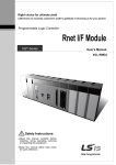
The trip characteristic for a measuring element is shown in Fig. 1.
Compiled by:
Approved by:
Ferenc Radvánszki and Gyula Póka
László Eperjesi
Date:
14.09.2004
Page:
8/50
PROTECT
OGYD2-EP User’s manual
Electronics Co. Ltd
Id (trip)
*In
K = 0⋅8 (80%)
10
Id
K = 0⋅5 (50%)
5
I base setting
IOffset
Is (bias)
5
10
15
20
*In
Fig.1 The trip characteristic for a measuring element
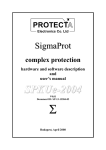
For an internal bus-bar fault the measuring principle described above can be seen in Fig.2.
Compiled by:
Approved by:
Ferenc Radvánszki and Gyula Póka
László Eperjesi
Date:
14.09.2004
Page:
9/50
PROTECT
OGYD2-EP User’s manual
Electronics Co. Ltd
Fig.2 Measurement of internal bus-bar fault
The top of Fig.2 shows a simple bus-bar section configuration. Supplying the internal fault,
all currents flow in the same direction. The “Idp” time function in the second row of Fig.2,
drawn dashed, in the first half period has half value, because of the average calculation
I d . p − I d . p−10 ms
I d . p1 =
is based on the sampled value summation I d . p = ∑ I p and that sampled
2
10 ms before.
Compiled by:
Approved by:
Ferenc Radvánszki and Gyula Póka
László Eperjesi
Date:
14.09.2004
Page:
10/50
PROTECT
OGYD2-EP User’s manual
Electronics Co. Ltd
The “Isp” time function in the third row of Fig.2, drawn dashed, in the first half period has
I s . p + I s. p −10 ms
half value too, because of the average calculation I s. p1 =
, based on the
2
calculation mentioned before: I s. p = ∑ I p − a , if I p − a > 0 ), and because in normal
(
)
(
)
operation these values are continuously zero, as the “a” load current value is continuously
subtracted.
The bottom curve in Fig.2 shows Id and K*Is, which is the result of averaging 10 values:
10
Id =
∑ I d . pn
n =1
10
10
and K * Is = K *
∑I
n =1
s . pn
10
.
As before fault both Id and K*Is are zero the bottom curves in Fig. 2 increase step-by-step. In
the evaluation there is no intentional time delay or measured value exclusion. Tripping is
generated after 8 consecutive starting of the function. In case of internal fault as Fig.2 shows,
Id is continuously above K*Is, and after 8 comparisons the measuring element automatically
generates trip command. The command detected on the output relay is somewhat delayed
because of the operating time of the relay. The duration of the trip impulse is at least 500 ms,
the algorithm resets the command only after this time delay, if the conditions are reset
meantime. The drop-off ratio of the trip current is 1.
The bus-bar differential protection function can be disabled by an output variable (BB prot.
disable) of the PROTLOG equations. Using the parameter “BB diff. prot.disable” the
function can be fix disabled. In this case the assigned LED is signaling the disabled state, and
the PROTLOG equation has no influence.
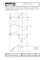
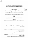
The measuring principle in case of external fault is shown in Fig. 3.
Compiled by:
Approved by:
Ferenc Radvánszki and Gyula Póka
László Eperjesi
Date:
14.09.2004
Page:
11/50
PROTECT
OGYD2-EP User’s manual
Electronics Co. Ltd
„a”
Fig.3 Measurement of external fault
The top of Fig.3 shows a simple bus-bar section configuration, where Bay 4. has an external
fault. The currents in the healthy bays flow in the same direction, the fault current in Bay 4 is
the sum of these currents, and flows in inverse direction. Because of concentrated fault
current the CT in Bay 4 can be saturated. The second row of Fig.3 shows that opposite to the
sum of the healthy bay current (I1+I2+I3) the I4 bay current is not exactly the inverse, some
current samples are “missing” as caused by the distortion of the saturation. (The Fig.3 shows
Compiled by:
Approved by:
Ferenc Radvánszki and Gyula Póka
László Eperjesi
Date:
14.09.2004
Page:
12/50
PROTECT
OGYD2-EP User’s manual
Electronics Co. Ltd
“ideal” saturation!). In calculation of Idp, this “missing” current section is detected (dashed
line)
The third section of Fig. 3 shows the calculated Isp (dashed line too). It is clearly seen that the
biasing current increases immediately, and because of the saturation the increasing is slowed
down only at the end of the first half period. Of course in the first half period the values are
halved, as in case of internal fault.
As the fourth section of Fig. 3 shows the summed K*Is biasing current is continuously above
Id. So in case of K=0.8 the comparison performed in each millisecond never cause operation
of the differential protection function.
Based on Fig.3 the limits of the measuring principle of OGYD2 can be explained:
• Let’s suppose that the current transformer of the faulty bay saturates at IT current, and
that the current transformer can not deliver secondary current in saturated state (“ideal
saturation”).
If the sum of the currents on healthy bays is Izm (this is the maximal fault current,
when the protection operates correctly), in the faulty bay it is only IT (less than the
fault current) then the trip current is:
Id = Izm − I T .
The biasing current is with similar procedure:
K * Is = K * [(Izm + I T ) − n * a ]
where
n is the number of the bays,
a is the subtracted load current value.
In the following explanation a=0 setting value is supposed.
The trip equation is:
Id ≥ K * Is
which yields with substitution of the expressions above:
1+ K
Izm = I T
1− K
This equation helps when setting the K biasing factor supposing the maximal Izm or
determination of the maximal Izm in case of a given K setting.
Example: if the current transformer with rated current of 250 A primary saturates at
IT=2500 A, and the setting is K=0.5, then Izm= 3*IT=30*In=7500 A, if the setting is
K=0.8, then Izm= 9*IT=90*In=22500 A.
These data show, that for stationary state this protection provides a sufficient
protection.
•
If a current transformer is at the saturation limit in stationary state, (the fault current is
equal with the saturation value) then the flux reaches the saturation level, and the
“time to saturation” of the current transformer is 10 ms, and the current peak value is
ITcs=1.42*IT. If the current exceeds this value, then the current transformer saturates in
Compiled by:
Approved by:
Ferenc Radvánszki and Gyula Póka
László Eperjesi
Date:
14.09.2004
Page:
13/50
PROTECT
OGYD2-EP User’s manual
Electronics Co. Ltd
shorter time than 10 ms. based on the principle of equalty of areas the “time to
saturation” can be calculated as shown below (supposing “ideal” saturation):
1
2
tT = arccos 1 −
Izm
ω
IT
The maximal current, at which the current transmission of the current transformer is
distortion-less, which means that the current value at the moment of tT, related to the
I Tcs = 2 I T is:
I cs Izm
=
sin ωtT
I Tcs
IT
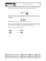
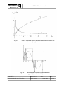
The relations of these last two equations are shown in Fig. 4.a.
In case of a bus-bar with high short-circuit power the current transformer in the faulty
bay can be extremely saturated. Fig, 4.b shows two cases supposing “ideal” saturation.
In one case the time to saturation is 2 ms, in the other one it is 3 ms.
Based on the equations above the data are:
Izm
=5
IT
Izm
for
= 10
IT
for
I cs
=4
I Tcs
I
tT=2 ms and cs = 6
I Tcs
tT=3 ms and
Compiled by:
Approved by:
Ferenc Radvánszki and Gyula Póka
László Eperjesi
Date:
14.09.2004
Page:
14/50
PROTECT
OGYD2-EP User’s manual
Electronics Co. Ltd
Fig. 4.a
Time to saturation and the maximal transmitted current as the
function of the fault curent
Fig. 4.b
External fault causing extreme saturation
(supposing „ideal saturation”)
Compiled by:
Approved by:
Ferenc Radvánszki and Gyula Póka
László Eperjesi
Date:
14.09.2004
Page:
15/50
PROTECT
OGYD2-EP User’s manual
Electronics Co. Ltd
In case of external fault, even if the time to saturation is below 2 ms, there can be a
considerable time span, when Id>K*Is see Fig. 5. If this time is more than 8 ms, then the
measuring element generates a false trip command for external fault. This can occur in case of
high grade of transient saturation.
Fig. 5 External
fault with
1 ms time to
saturation
Compiled by:
Approved by:
Ferenc Radvánszki and Gyula Póka
László Eperjesi
Date:
14.09.2004
Page:
16/50
PROTECT
OGYD2-EP User’s manual
Electronics Co. Ltd
To avoid false trip command in case of external fault the OGYD2-EP device uses the
following method. As it can be seen in Fig. 5, at the beginning the biasing current is always
above the trip current, and in this time the measuring element blocks the trip command. This
blocking can never occur in case of internal fault, so in case of initial blocking it can be
always supposed that the fault is an external fault. So if the biasing current is above the
tripping current even in one step, then the measuring element switches over from 8 to 25 for
the count limit of tripping conditions (the duration is in this case 25 ms). This method assures
correct operation in case of extreme saturation as well.
The application of the method above does not result increasing operating time in case of
internal fault, because the 25 times checking can occur only for external faults. The only
exception is the “transition” of the fault location, when a close external fault evolves to
internal fault. In this special case the operation can be expected only after a 25 ms time delay,
but this method increases stability for external faults.
To avoid false tripping OGYD2-EP applies another safety method too. All bay units of the
bus-bar differential protection system monitor in all three phases the increasing and
decreasing periods of the bay currents. If in a bay the current increases, subsequently
decreases within 3 ms, then the protection algorithm keeps the last high value up to the end of
the half period. This method supplies at least partly the missing current samples, and at the
same time no excess in biasing current can occur, because this curve shape results the same
current value as the unsaturated one if the time span is 2 ms, and about the half value if the
time span is 1 ms. (See Fig. 4 b.).
This method results suitable biasing and a small Id value, which assures stability for
stationary external faults even in case of 40 times saturation current (e.g. for n=10 this means
10*40=400 times rated current).
This explanation proves the use of the method keeping the last high value up to the end of the
half period.
It has to be mentioned that even in extreme cases the method of changing the number of
checking from 8 to 25 can prevent false tripping with high reliability. As the result of the
application of the methods explained above the operation of the protection is reliable in case
of extreme stationary saturation and for high residual flux value as well. The only
requirement of the protection is tT≥1 ms minimal time to saturation (the time span, when the
current transition is distortion-less).
The bus-bar differential protection measures in all three phases, but the trip command is
generated common for all three phases of the circuit breaker.
Compiled by:
Approved by:
Ferenc Radvánszki and Gyula Póka
László Eperjesi
Date:
14.09.2004
Page:
17/50
PROTECT
OGYD2-EP User’s manual
Electronics Co. Ltd
3.1.2 Voltage breakdown condition
The trip command is released only if in the affected bay and in the affected phase the voltage
collapses.
To perform this supervision all bay units monitor the presence of the voltage with a quick
voltage measuring function. The result of the supervision is sent to the CPU OGYD in every
milliseconds. If the voltage is below 0.7Un, the function drops. If any of the voltage functions
signals low voltage then the operation of the assigned measuring element is enabled, and if
the currents fulfill the differential criteria the algorithm generates a trip command.
If the differential protection function started and the bay units received trip command then
this voltage condition does not play any role. The trip command resets only if the currents are
outside the tripping zone of the characteristics.
A voltage monitoring function can allow trip command only for 5 s, then the function is
disabled until the measured voltage returns to healthy state again, or a new initializing is
performed (caused by disconnector status change, switching on, parameter changes).
If all voltage monitoring functions assigned to a measuring element detect low voltage then
the bus-bar section is considered to be disconnected, and the operation of the bus-bar
differential protection is enabled again (to cover the switch-on-to-fault condition).
If the trip command is disabled by the voltage condition then the “On-line” screen of the
connected PC displays the status signal as “U>disable: +“. If one or more voltage
supervisions detect low voltage then the display changes form “+“ to “-”. At that moment a 5
s timer is started, and when it expires then the operated voltage supervision function is
disabled. As a consequence the signal shows “+“ again.
3.1.3 Supervising the current transformer circuits
Each measuring element supervises he current transformers the bay of which is connected to
the bus-bar section.
The central unit measures with each measuring element in all three phases the current
differences. If the differential current value in any phases is above the current error setting
Iset(CT error), but the associated voltage is healthy (U>block:-), then a timer is started (CT
error delay). If this timer expires CT error signal is generated and the trip command is
blocked. The condition to start the timer is:
[U>block: −]*{(Idr>Iset[CT error])+(Ids>Iset[CT error])+(Idt>Iset[CT error])}
Compiled by:
Approved by:
Ferenc Radvánszki and Gyula Póka
László Eperjesi
Date:
14.09.2004
Page:
18/50
PROTECT
OGYD2-EP User’s manual
Electronics Co. Ltd
The CT error state is considered to reset if the differential current is below the current error
setting in all three phases:
(Idr<Iset[CT error])*(Ids<Iset[CT error])*(Idt<Iset[CT error])
If the conditions are fulfilled then after a drop-off delay the status is reset, and the protection
is operable again. The drop of delay timer and the start delay timer operate with the same
parameter setting (CT error delay).
During normal operation of the power system there is no possibility to set the CT error state.
If however the protection is tested in the laboratory, or current is injected into the device, care
must be taken, because the CT error state after the time delay disables trip command.
3.1.4 Fiber optic cable supervision
Additionally to the data communication the COM3 modules inserted in the central unit have
the important task to supervise the healthy state of the fiber optic cable lines. A precise
integrating algorithm is applied to recognize the line error within 3 ms. The signal of the error
state is transmitted to the CPU OGYD module. This line error signal disables trip command.
3.2 Digital breaker failure protection
3.2.1 Method of operation
The operation of the digital breaker failure protection integrated in the OGYD2-EP device is
as follows:
A breaker failure protection function is assigned to each measuring element. In the
supervision only those bays are included which are connected to the bus-bar section.
All bay units collect breaker failure start commands from the bay-oriented protection
functions, and checks if current is flowing in the bay, and supervises if really trip command is
sent to any of the circuit breaker trip coils of the bay. If all conditions are fulfilled then
without any time delay the bay unit sends a message to the central unit with the content that
the possible state is breaker failure.
The starting conditions for breaker failure protection starting are as follows:
a)
In a transformer bay (no current supervision is involved):
BFstart*(RTripI.+RTripII.+STripI.+STripII.+TKiI.+TTripII.)
b)
In a bay without transformer (the current is checked as well):
BFstart*[(RTripI.+RTripII.)*Ir+(STripI.+STripII.)*Is+(TKiI.+TTripII.)*It]
Compiled by:
Approved by:
Ferenc Radvánszki and Gyula Póka
László Eperjesi
Date:
14.09.2004
Page:
19/50
PROTECT
OGYD2-EP User’s manual
Electronics Co. Ltd
In these conditions:
BFstart
the bay unit detected breaker failure start external signal in the
dedicated optically isolated digital inputs
RTripI., RTripII, … the bay unit detected trip command as sent to the indicated phase and
indicated trip coil in the dedicated optically isolated digital inputs
Ir, Is, It
the OXO modules in the bay unit measured the current in the indicated
phase and generated permission, because the measured current value is
above 0.1*In(bay).
The central unit receives the messages as generated in the bay units according to the
conditions above, and starts the t1 and t2 timers. The time delays are set by parameters (BF
timer 1, BF timer2). In case of timeout of t1 a command is sent to the selected bay unit to
generate a new trip command to both trip coils of the circuit breaker (the duration of the
command is 500 ms). If this command has no effect, and the conditions are permanently
fulfilled, then after t2 time delay all circuit breakers connected to the bus-bar section receive
the trip command (the duration of the command is 500 ms here too).
The breaker failure protection supervises the individual phases but generates a three-phase
trip command.
The breaker failure protection function can be disabled using an output of the PROTLOG
equation (BF prot disable). The parameter (BF protection disable) disables the function
permanently. In this case the LED BF disabled indicates the disabled state, and the
PROTLOG equation has no further effect.
3.3 Test mode
For the time of commissioning or checks the protection can be set to test mode. In this case
no trip commands are generated. The parameter to be set is “Test”. The parameter value is to
be changed to “+” to set the device in test mode.
Compiled by:
Approved by:
Ferenc Radvánszki and Gyula Póka
László Eperjesi
Date:
14.09.2004
Page:
20/50
PROTECT
OGYD2-EP User’s manual
Electronics Co. Ltd
4 Information from and to OGYD2-EP bus-bar differential
and breaker failure protection
4.1 Parameter setting and setting ranges
Setting of the differential characteristics (primary current values):
NAME
I base setting
Biasing
I Offset
Iset(CT error)
DIM.
[A]
[%]
[A]
[A]
RANGE/STEP
(50-5000/10)
50-80/5
(0-5000/10)
(10-5000/25)
Explanation
Differential characteristics current base setting
Slope of the characteristic
Expected maximal bay load current (“a”)
CT current error setting
Bay setting data as stored in the central unit (primary CT rated current values):
NAME
In[1st bay name ]
In[2nd bay name ]
…
In[nth bay name ]
DIM.
[CT Pr. A]
[CT Pr. A]
RANGE/STEP
(50-5000/25)
(50-5000/25)
FIX DISCONNECTED
+/+/-
[CT Pr. A]
(50-5000/25)
+/-
The bay is considered to be permanently disconnected, if the setting is “+”.
Timer parameters
NAME
CT error delay
BF timer 1
BF timer 2
Disc. status error timer
DIM.
[ms]
[ms]
[ms]
[s]
RANGE/STEP
(100-32000/10)
(0-32000/10)
(0-32000/10)
(1-60/1)
Explanation
Timer setting for CT error signaling
Breaker failure timer 1
Breaker failure timer 2
Disconnector status error time delay
Voltage condition parameter:
NAME
Bay voltage condition
Value
0.7 Un
Explanation
Fix setting
Logic parameters:
NAME
Bay fix disconnected
Bus-bar diff.prot disable
BF protection disable
Explanation
Bay fix disconnected
Bus-bar differential protection disable
Breaker failure protection disable
Compiled by:
Approved by:
Ferenc Radvánszki and Gyula Póka
László Eperjesi
Date:
14.09.2004
Page:
21/50
PROTECT
OGYD2-EP User’s manual
Electronics Co. Ltd
Communication parameters
NAME
Opto/RS (0/1)
FiberOpticLoop 1=Yes
BaudRate:
Device Code:
Station Code:
Explanation
Selection of serial port: fiber optic connector or RS232
1=operation in loop, 0= radial connection
Setting range: 150 … 19200 Baud, step *2
Device identifier, setting range 0 … 254
Station identifier, setting range 0 … 254
4.2 List of evaluated events
NAME
Protection start:
Protection reset:
BB diff prot. operation
BF prot. operation
Trip bay 1
Trip bay 2
…
Trip bay n
Explanation
‘yy . mm . dd
hh : mm : ss : ms
‘yy . mm . dd
hh : mm : ss : ms
Bus-bar differential protection operated
Breaker failure protection operated
Trip command to bay 1
Trip command to bay 2
Trip command to bay n
4.3 List of digital events
NAME
Explanation
Test state
Commissioning state
BB diff prot. disabled
Disabled state of the bus-bar differential protection function
BF prot. disabled
Disabled state of the breaker failure protection function
OX error
OXO fiber optic driver or fiber optic connection error
Disconn. error
Disconnector status signal discrepancy
Bay 1 trip
Bay 1 is disconnected by the protection
Bay 2 trip
Bay 2 is disconnected by the protection
..
Bay n trip
Bay n is disconnected by the protection
For each measuring element:
M1 trip R
Trip command of the measuring element 1 in phase R
M1 trip S
Trip command of the measuring element 1 in phase S
M1 trip T
Trip command of the measuring element 1 in phase T
M1 BF prot. start
Measuring element 1: breaker failure protection start
M1 BF prot. trip
Measuring element 1: breaker failure protection trip command
M1 CT circuit error
Measuring element 1: current transformer circuit error
M1 VT OK
Measuring element 1: voltage transformer OK (or permanently
neglected)
Compiled by:
Approved by:
Ferenc Radvánszki and Gyula Póka
László Eperjesi
Date:
14.09.2004
Page:
22/50
PROTECT
OGYD2-EP User’s manual
Electronics Co. Ltd
4.4 List of LCD messages
MESSAGE
DSP error
BB diff. prot. trip
BF prot. trip
CT circuit error
Explanation
Digital signal processor error
Bus-bar differential protection generated trip command
Breaker failure protection generated trip command
Current transformer circuit error
4.5 On-line information
The On-line screen is displayed on a connected PC, running Protect for Windows operating
software under Windows environment. (See EuroProt complex protection hardware and
software description and user’s manual). The measured current values are displayed in
primary Ampers. The bay currents are approximate values based on rectified average
measurement.
Information for each measuring elements:
Measuring element 1
Delta:
Summa:
Idr
0A
Isr 0 A
Ids
0 A Iss
0A
Idt
0A
Ist
0A
Trip R
Trip S
Trip T
BF start
BF trip
CT error
U>block
-
Bay information:
[1st bay name
[2nd bay name
…
[nth bay name
] current
] current
123
123
Trip
Trip
-
] current
123
Trip
-
Compiled by:
Approved by:
Ferenc Radvánszki and Gyula Póka
László Eperjesi
Date:
14.09.2004
Page:
23/50
PROTECT
OGYD2-EP User’s manual
Electronics Co. Ltd
Common information:
Test state:
BB prot disabled
BF prot disabled
Opto error
Disconn. error
-
Service information:
O(1..8)=00 O(9..16)=00
Internal variables (1..16):
Timer start:
Timer timeout:
10 ms timer start:
10 ms timer timeout:
O(17..24)=00 O(25..32)=00
0000
0000
0000
00
00
Timers for each measuring element:
CT error timer start
CT error timer drop-off
VT timer
BF timer
0
0
0
0
4.6 Inputs and outputs of the PROTLOG equations
Inputs (source variables):
INPUT VARIABLE
O5 …O8
BB operated
BF operated
CT error
M1 … Mm trip
Disc. status error timeout
OX error
Disc. status error
SW1 ackn.
Explanation
State of optically isolated inputs 5 … 8
Bus-bar protection operated
Breaker failure protection operated
Current transformer circuit error
Measuring element 1 … m trip command
Disconector status error timeout
OXO fiber optic connection error
Disconnector status error
Acknowledgement with SW1 push-button
All input variables are repeated with “*”, where “*” means latched signal.
Compiled by:
Approved by:
Ferenc Radvánszki and Gyula Póka
László Eperjesi
Date:
14.09.2004
Page:
24/50
PROTECT
OGYD2-EP User’s manual
Electronics Co. Ltd
Outputs:
OUTPUT VARIABLE
R13 … R16
BB prot. disable
BF prot. disable
Ackn.
Explanation
Operation of output relay 13 … 16
Bus-bar protection disable
Breaker failure protection disable
Acknowledgement
4.7 LED assignment and SW buttons
LED
1.) LCD
2.)
3.)
4.)
5.)
6.)
7.)
∆I>
Disconn.
Line error
BF disable.
BB disable.
Test
SW switches
SW2 (upper)
SW1 (lower)
Explanation
Warning LED: indicates message on the display, parameter
changes or need of acknowledgement
Differential protection function operated
Disconnector status signal error
Fiber optic connection error
Breaker failure protection disabled by parameter setting
Bus-bar diff. protection disabled by parameter setting
Test state as set by parameter
Explanation
No assignment in this configuration
Acknowledgement (valid for the bay units too)
Compiled by:
Approved by:
Ferenc Radvánszki and Gyula Póka
László Eperjesi
Date:
14.09.2004
Page:
25/50
PROTECT
OGYD2-EP User’s manual
Electronics Co. Ltd
5 Construction, external connections
The construction and external connections of the OGYD2-EP bus-bar differential protection
and breaker failure protection are explained in Figures 6…15. Figures 6 … 11 show the
connections of the bay unit, Fig. 12 … 15 show those of the central unit.
5.1 Drawings for a DTVA-OGYD2-EP device
Fig. 6 shows the external connections of a combined DTVA-OGYD2-EP device (distance
protection and automatic recloser combined with the bay unit of the bus-bar protection),
important from the OGYD2-EP functionality. Some connections are common with the
functions of the DTVA functions (e.g. current and voltage inputs, power supply, trip
command, etc.), others serve the bus-bar functions only (e.g. disconnector status signals, fiber
optic inputs for the trip commands). This Figure does not show the two fiber optic connectors
for the laser-driver OXO module.
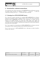
Fig. 7 is the complete list of connections of a DTVA-OGYD2-EP device (distance protection
and automatic recloser combined with the bay unit of the bus-bar protection).
Fig. 8 is the rear view of a DTVA-OGYD2-EP device, indicating the module identifiers,
positions and connectors.
Compiled by:
Approved by:
Ferenc Radvánszki and Gyula Póka
László Eperjesi
Date:
14.09.2004
Page:
26/50
PROTECT
OGYD2-EP User’s manual
Electronics Co. Ltd
Fig. 6 Connections serving the OGYD2-EP functions
of a bay unit of DTVA-OGYD2-EP type
Compiled by:
Approved by:
Ferenc Radvánszki and Gyula Póka
László Eperjesi
Date:
14.09.2004
Page:
27/50
PROTECT
OGYD2-EP User’s manual
Electronics Co. Ltd
Nr.
6
5
4
3
2
1
Denomination
IR
IR
IS
IS
IT
IT
"K"
M+
TRIP I.R
M+
TRIP I.S
M I.+
TRIP I.T T
J+
CB OFF
TRIP II.R
TRIP II.S
TRIP II.T
OPTO-
02
2
03
3
04
4
6
5
4
3
2
1
ET
Nr.
9↔
10↔
9↔
11↔
9↔
12↔
13↔
74
16↔
17↔
18↔
1
2
3
4
5
6
7
8
9
10
11
12
VT2
Denomination
U0
UR
U0
US
U0
UT
ET
5↔
6
5↔
7
5↔
8
R4EI
"I"
Denomination
ET
Nr.
M I.+
9↔
TRIP I.R.
M I.+
10↔
9↔
TRIP I S.
M I.+
11↔
9↔
TRIP I.T
J+
12↔
13↔
1
2
3
4
5
6
7
8
9
10
11
12
ON
14
R4I
"H"
Denomination
ET
Nr.
M II.+
15↔
TRIP II.R
M II.+
16↔
15↔
TRIP II.S
M II.+
17↔
15↔
TRIP II.T
+
18↔
19
1
2
3
4
5
6
7
8
9
10
11
12
K8
20
R4E
Denomination
ET
SELF TEST +
SELF TEST -
21
22
+
23
K10(AUT.DISABL.)
+
24
25
K11
+
26
27
K12
28
69↔
R4
Nr.
"F"
Denomination
ET
Nr..
+
29
K13.
+
30
31
K14
+
32
33
K15
+
34
35
K16
36
1
2
3
4
5
6
7
8
9
10
11
12
"C"
O
Nr.
Denomination
1
2
3
4
5
6
7
8
9
Nr.
"J"
Denomination
"G"
1
2
3
4
5
6
7
8
9
10
11
12
ET
U
Nr.
1
2
3
4
5
6
7
8
9
10
11
12
13
"S" "T"
CT2*
"U" "V"
Bus „B” OFF
Bus „B” ON
Bus „K” OFF
Bus „K” ON
BF start
TRIP I.R
TRIP I.S
TRIP I.T
OPTO-(1-8)
ET
64
63
62
61
65
10↔
11↔
12↔
69↔
R4E
ET
Nr.
+
37
K17
+
38
39
K18
+
40
41
K19
+
K20
42
43
44
1
2
3
4
5
6
7
8
9
"A" "B"
Nr.
1
2
3
4
"E"
Denomination
O
"D"
Denomination
Synch.trip.enabl. +
Comm.error +
Remote enabl. +
Remote disabl. +
Aut. block.+
NHSC +
Manual ON +
Remote trip.
OPTO-(1-8)
ET
Nr.
45
46
47
48
49
50
51
52
69↔
1
2
3
4
5
6
7
8
9
O
Denomination
AR start
R ON status
S ON status
T ON status
AR disable
ON disable
Input 15
Input 16
OPTO-(1-8)
T4
Denomination
Power supply +
Power supply Time synch.+
Time synch -
ET
72
73
Fig. 7 Complete list of connections of a DTVA-OGYD2-EP device
Compiled by:
Approved by:
Ferenc Radvánszki and Gyula Póka
László Eperjesi
Date:
14.09.2004
Page:
28/50
ET
53
54
55
56
57
58
59
60
69↔
PROTECT
OGYD2-EP User’s manual
Electronics Co. Ltd
Fig. 8 Rear view of a DTVA-OGYD2-EP device
Compiled by:
Approved by:
Ferenc Radvánszki and Gyula Póka
László Eperjesi
Date:
14.09.2004
Page:
29/50
PROTECT
OGYD2-EP User’s manual
Electronics Co. Ltd
5.2 Drawings for a DTI-OGYD2-EP device
Fig. 9 shows the external connections of a combined DTI-OGYD2-EP device (overcurrent
protection combined with the bay unit of the bus-bar protection), important from the OGYD2EP functionality. Some connections are common with the functions of the DTI functions (e.g.
current and voltage inputs, power supply, trip command, etc.), others serve the bus-bar
functions only (e.g. disconnector status signals, fiber optic inputs for the trip commands).
This Figure does not show the two fiber optic connectors for the laser-driver OXO module.
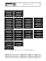
Fig. 10 is the complete list of connections of a DTI-OGYD2-EP device (overcurrent
protection combined with the bay unit of the bus-bar protection).
Fig. 11 is the rear view of a DTI-OGYD2-EP device, indicating the module identifiers,
positions and connectors.
Compiled by:
Approved by:
Ferenc Radvánszki and Gyula Póka
László Eperjesi
Date:
14.09.2004
Page:
30/50
PROTECT
OGYD2-EP User’s manual
Electronics Co. Ltd
Fig. 9 Connections serving the OGYD2-EP functions
of a bay unit of DTI-OGYD2-EP type
Compiled by:
Approved by:
Ferenc Radvánszki and Gyula Póka
László Eperjesi
Date:
14.09.2004
Page:
31/50
PROTECT
OGYD2-EP User’s manual
Electronics Co. Ltd
"U" "V"
Nr.
6
5
4
3
2
1
CT2*
"S" "T"
Denomination
IR
IR
IS
IS
IT
IT
"K"
Nr.
1
2
3
4
5
6
7
8
9
10
11
12
13
1
2
3
4
5
6
7
8
9
Nr.
02
2
03
3
04
4
6
5
4
3
2
1
U
Denomination
M I.+
TRIP I.R.
M I.+
TRIP I.S
M I.+
TRIP I.T
J+
CB OFF
TRIP II.R
TRIP II.S
TRIP II.T
INPUT
OPTO-
VT2
Denomination
ET
U0
UR
U0
US
U0
UT
5↔
6
5↔
7
5↔
8
"J"
R4EÍ
ET
Nr.
Denomination
9↔
10↔
9↔
11↔
9↔
12↔
13↔
34
16↔
17↔
18↔
1
2
3
4
5
6
7
8
9
10
11
12
"I"
ET
Nr.
M I.+
9↔
TRIP I.R.
M I.+
10↔
9↔
TRIP I.S.
M I.+
11↔
9↔
TRIP I.T
K4+ (J+)
12↔
13
1
2
3
4
5
6
7
8
9
10
11
12
K4 (AUT.DISABL.)
14
R4IÜ
Denomination
ET
M II.+
15↔
TRIP II.R.
M II.+
16↔
15↔
TRIP II.S
M II.+
17↔
15↔
TRIP II.T
K8+ (SELF TEST.+)
18↔
19
.
K8 (SELF TEST)
20
29↔
"C"
Nr.
ET
O
Denomination
BUS „B” OFF
BUS „B” ON
BUS „K”OFF
BUS „K”ON
BF START
TRIP I.R
TRIP I.S
TRIP I.T
OPTO-(1-8)
Fig. 10
"A" "B"
ET
Nr.
25
24
23
22
21
10↔
11↔
12↔
29↔
1
2
3
4
T4
Denomination
POWER SUPPLY +
POWER SUPPLY TIME SYNCH.+
TIME SYNCH.-
ET
32
33
Complete list of connections of a DTI-OGYD2-EP device
Compiled by:
Approved by:
Ferenc Radvánszki and Gyula Póka
László Eperjesi
Date:
14.09.2004
Page:
32/50
PROTECT
OGYD2-EP User’s manual
Electronics Co. Ltd
Fig.11
Rear view of a DTI-OGYD2-EP device
Compiled by:
Approved by:
Ferenc Radvánszki and Gyula Póka
László Eperjesi
Date:
14.09.2004
Page:
33/50
PROTECT
OGYD2-EP User’s manual
Electronics Co. Ltd
If the protected bus-bar can be divided into sections by bus disconnectors, then the status
signals of these disconnectors are input to the central unit. In case of bay structure a dedicated
device can be assigned to the disconnector bay, and this device can be connected via highspeed fiber optic cable to the central unit. This bay unit can include all necessary modules
(power supply unit, central CPU unit, OXO fiber optic cable driver unit.)
As an example the dedicated disconnector unit may connect the signal circuits according to
Fig. 12. The realization depends on the substation configuration, and PROTECTA Co. Ltd.
delivers the actual connection diagrams with the OGYD2-EP devices.
Fig. 12
Connection of a bus-bar disconnector configuration
5.3 Drawings for an OGYD2-EP central unit
The central unit of the OGYD2-EP bus-bar protection system is a fully numerical device with
main processor, additional signal processors and fiber optic input units for three fiber optic
cable pair connections each.
The main connections of a central unit are drawn in Fig. 13.
Compiled by:
Approved by:
Ferenc Radvánszki and Gyula Póka
László Eperjesi
Date:
14.09.2004
Page:
34/50
PROTECT
OGYD2-EP User’s manual
Electronics Co. Ltd
Fig. 13
Connections of the OGYD2-EP central unit
Compiled by:
Approved by:
Ferenc Radvánszki and Gyula Póka
László Eperjesi
Date:
14.09.2004
Page:
35/50
PROTECT
OGYD2-EP User’s manual
Electronics Co. Ltd
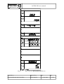
Fig. 14 is the complete list of connections of an OGYD2-EP central device.
Fig. 15 is the rear view of an OGYD2-EP central device, indicating the module identifiers,
positions and connectors.
"H"
R4E
"G"
Nr.
Denomination
ET
Nr.
1
2
3
4
5
6
7
8
9
10
11
12
K1+(I1+)
K1(SELF TEST)
1↔
12
K2+(I1+)
1↔
K2(BF OPER)
K3+
13
1
2
3
4
5
6
7
8
9
10
11
12
K3
K4+
K4
"C"
Megnevezés
1
2
3
4
Nr.
K5+ (I1+)
1↔
K5 (M1)
K6+ (I1+)
2
1↔
K6 (M2)
K7+
3
1
2
3
4
5
6
7
8
9
10
11
12
K7
K8+
K8
"E"
R4E
Denomination
ET
1
2
3
4
5
6
7
8
9
10
11
12
K91+
K9
K10+
K10
K11+
K11
K12+
K12
R4
Nr.
Denomination
6↔
K13 (ZI)
K14+(+)
7
6↔
K14 (M1Z)
K15+(+)
8
6↔
K15 (M2Z)
K16+
9
K16
18
19
20
21
22
23
24
25
26
T4
Megnevezés
Ks
POWER SUPPLY+
POWER SUPPLYPCLOCK SYNCH.+
CLOCK SYNCH.-
Fig. 14
16
17
14
15
Complete list of connections of an OGYD2-EP central device
Compiled by:
Approved by:
Ferenc Radvánszki and Gyula Póka
László Eperjesi
Date:
14.09.2004
ET
K13+(+)
Ks
Input 1
Input 2
Input 3
Input 4
Input 5
Input 6
Input 7
Input 8
Opto-(1-8)
"A" "B"
sz.
"F"
ET
O (BUS-BAR DISC)
sz.
1
2
3
4
5
6
7
8
9
R4
Denomination
Page:
36/50
PROTECT
OGYD2-EP User’s manual
Electronics Co. Ltd
Fig. 15
rear view of an OGYD2-EP central device (example)
Compiled by:
Approved by:
Ferenc Radvánszki and Gyula Póka
László Eperjesi
Date:
14.09.2004
Page:
37/50
PROTECT
OGYD2-EP User’s manual
Electronics Co. Ltd
Compiled by:
Approved by:
Ferenc Radvánszki and Gyula Póka
László Eperjesi
Date:
14.09.2004
Page:
38/50
PROTECT
OGYD2-EP User’s manual
Electronics Co. Ltd
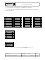
5.4 Modules of the central unit
The remaining part of this chapter describes the modules of the central unit, as an example for
the possible configurations. The first underlined italic letter is the location in the rack. The
second underlined bold “name” is the identifier of the module as the rear lever of the module
shows. The brackets contain the identifier of the printed circuit board, then the bold
underlined number is the factory identifier.
A.) T [EU-TAP(2A) P368] 3843
This is the power supply unit of the OGYD2-EP device with DC/DC converter. The
same power supply unit can be connected to 110 V or 220 V substation battery
voltage, since the unit has extreme high voltage tolerance: it extends from 88 V to
310 V. Additionally, the input is polarity protected. There is a digital optical coupler
input in the board for clock synchronization.
[EU-TAST P369/4] 4732 or 5629 This module can not be seen in the readyB.)
mounted state of the device (this is why it does not have handle identifier). This
module is located behind the front plate of the device, it can be accessed after
removing the front plate. The board serves man-machine interface of the front plate:
the keyboard, the connector for serial communication, the LED-s, etc. Both the front
plate from the front side, and the printed circuit boards of the other modules from
rear side are plugged to this plate.
C.) O [EU-OPTO P354] 4733 Eight optically isolated binary inputs.
D.) O [EU-OPTO P354] 4733 Eight optically isolated binary inputs.
E.) O [EU-OPTO P354] 4733 Eight optically isolated binary inputs.
F.) R4 [EU-RELAY P424] 4731 Four output relays (K13, K14, K15, K16).
G.) R4 [EU-RELAY P424] 4758 Four output relays (K9, K10, K11, K12).
H.) R4E [EU-RELAY P424] 4731 Four output relays (K5, K6, K7, K8).
I.) R4 [EU-RELAY P424] 4758 Four output relays (K1, K2, K3, K4).
J.) CPU MAIN [EU-198A P436] 7069 Central unit with the main processor, memories,
I/O divers, serial input/output, communication optical fiber cable connector with its
driver, integrated program monitoring with Watch Dog, event memory for 50 events,
event sequence recorder for 300 events with 1 ms resolution.
K.) CPU DSP [EU-196A P352] 5613 Digital signal processor for the differential protection
central function (CPU OGYD).
Compiled by:
Approved by:
Ferenc Radvánszki and Gyula Póka
László Eperjesi
Date:
14.09.2004
Page:
39/50
PROTECT
OGYD2-EP User’s manual
Electronics Co. Ltd
L.) COM3 [EU-MULTICOM3 P479] COM3 board for three feeders or independent
disconnecor switches (e.g. sectionalisers), in order to receive the optical fiber cable
pairs.
M.) COM3 [EU-MULTICOM3 P479] COM3 board for three feeders or independent
disconnector switches (e.g. sectionalisers), in order to receive the optical fiber cable
pairs.
N.) COM3 [EU-MULTICOM3 P479] COM3 board for three feeders or independent
disconnector switches (e.g. sectionalisers), in order to receive the optical fiber cable
pairs.
O.) COM3 [EU-MULTICOM3 P479] COM3 board for three feeders or independent
disconnecor switches (e.g. sectionalisers), in order to receive the optical fiber cable
pairs.
P.) and R.) Cover plate (8TE empty place) or other two additional COM3 boards if
more feeders are connected to the bus-bar.
S.) és T.) Cover plate (8TE empty place) or other two additional COM3 boards if more
feeders are connected to the bus-bar.
U.) és V.) Cover plate (8TE empty place) or other two additional COM3 boards if more
feeders are connected to the bus-bar.
The structure of the OGYD2-EP numerical bus-bar and breaker failure protection and the
number of the applied COM3 communication units depends on the primary configuration of
the substation.
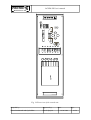
5.5 The front plate of the central unit and the large graphic display
Fig. 16 shows the front plate of the central unit.
The right side of the front plate contains the man-machine interface of all EuroProt devices.
(The detailed description is in the EuroProt complex protection hardware and software
description and user’s manual). The LED assignment is described in chapter 3.7.
The left side of the front plate is the location of the large graphic display. To the right of this
display the six push-buttons with left arrow serve the communication with the display.
When the device is energized the graphic display shows the bus-bar configuration with the
bays of the substation. This scheme shows the status of the disconnectors, and the status
signal errors are indicated as well.
Compiled by:
Approved by:
Ferenc Radvánszki and Gyula Póka
László Eperjesi
Date:
14.09.2004
Page:
40/50
PROTECT
OGYD2-EP User’s manual
Electronics Co. Ltd
Fig. 16 Front view of the central unit
Compiled by:
Approved by:
Ferenc Radvánszki and Gyula Póka
László Eperjesi
Date:
14.09.2004
Page:
41/50
PROTECT
OGYD2-EP User’s manual
Electronics Co. Ltd
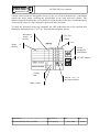
5.5.1 Displaying the bus-bar configuration:
If normal operation the graphical LCD displays the single line scheme of the bus-bar, and
shows the status information of the disconnect switches and the measured current values.
Bay name
Ir
Phase R
current of
the bay
Disconnect
status:
switch
Open
Closed
Status error (1, 1)
Status error (0, 0)
Bay is disabled,
the protection
excludes this bay.
Switch to
service
window
5.5.2 Service window:
The service window helps checking the balanced state of the differential protection. This
window displays the status of all disconnect switches in all bays, shows the measured current
values and the calculated delta and sum current values in all three phases.
If the protection is switched over to TEST state, there is possibility to check the consistency
of the current directions in the bays, and the checking of the trip commands is possible as
well.
The TEST state supports commissioning. In this case the bus-bar is considered to be a single
protected unit, independently of the state of the disconnect switches. The bays can be
included into the protected system one-by-one by pressing the ON push-button in the Test
Compiled by:
Approved by:
Ferenc Radvánszki and Gyula Póka
László Eperjesi
Date:
14.09.2004
Page:
42/50
PROTECT
OGYD2-EP User’s manual
Electronics Co. Ltd
column selected with the navigation arrows. In the row of the activated bays a checkmark
signals the active status, meaning the participation in the delta and sum currents. This
function supports checking the correct direction of the currents in the bays, and independently
of the current values, no trip command is generated in the test state.
To check the operation of the trip command the OFF push-button has to be activated after
finding the appropriate bay “C.B. Trip” field with the navigation arrows.
Disconnect
switch in
the bay
C.B. Trip
column
Test
Name of
the bay
Cursor
navigation
push-button
ON, OFF buttons
Current
sum
Switch over to
the status window
Delta current
Compiled by:
Approved by:
Ferenc Radvánszki and Gyula Póka
László Eperjesi
Date:
14.09.2004
Page:
43/50
PROTECT
OGYD2-EP User’s manual
Electronics Co. Ltd
5.5.3 The status window:
The status window displays the actual state of the individual bays. The energised state, the
load current, the breaker failure status and the healthy connection to the central unit via fibre
optic cable are displayed here.
if the breaker
failure signal is
in case of
communication error
if R phase current
>~10%
Bay name
if R phase voltage
<~70%
Status of the
bay in hex
format
Compiled by:
Approved by:
Ferenc Radvánszki and Gyula Póka
László Eperjesi
Date:
14.09.2004
Page:
44/50
PROTECT
OGYD2-EP User’s manual
Electronics Co. Ltd
In the bus-bar configuration window when pressing the arrow push-button to the right of the
service icon the list of the bays is displayed with disconnecor states and additional
information.
Pressing the “TEST” arrow the information is displayed to support commissioning. The busbar is displayed in this case independently of the disconnector states, containing only one
assigned measuring element. The bays can be connected one-by-one, independently of the
disconnector states. The “connected” bays are marked with a check-mark (√), indicating that
the current of the bay is involved in the calculation of the biasing current. This function
supports checking the correct polarity connection of the current transformers, and
independently of the current magnitude no trip command is generated. For easy checking the
“a” value (IOffset) is not subtracted from the measured currents. This method is useful in
commissioning and checking. In this “TEST” state trip command can be generated, which are
then performed by the bay units.
The individual bays can be disabled one-by-one with parameter setting. (On the PC’s
Parameter screen it means writing a “+” character for the Bay fix disconnected parameter.)
The disabled state is indicated on the display of the device with a wrench symbol. In this state
the central unit considers the bay – independently of the state of the disconnector - to be
disconnected, the current is reset to zero and the voltage is supposed to be healthy. All
functions operate with these substituted information.
The fix disconnection of the bay is useful if the bay is disconnected for maintenance.
The role of the arrow pushbuttons to the right of the display is indicated by software icons on
the screen. The actual configuration of the display is described individually attached to the
bus-bar protection device.
Compiled by:
Approved by:
Ferenc Radvánszki and Gyula Póka
László Eperjesi
Date:
14.09.2004
Page:
45/50
PROTECT
OGYD2-EP User’s manual
Electronics Co. Ltd
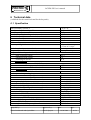
6 Technical data
(valid both for the central unit and for the bay units)
6.1 Specification
Rated secondary current, In
Rated secondary line voltage, Un
Rated frequency
Overload capacity, in voltage circuits, continuous
Overload capacity, in current circuits, continuous
1s
Dynamic current limit
Minimum "time-to-saturation" demand
Accuracy of digital timer
Optical coupler inputs (central unit)
Output relays (central unit)
Output contacts ratings (central unit)
rated switching voltage
continuous load current
switching on current
In signal circuits
breaking current at 220 V DC,
pure conductive circuit
L/R = 40 ms load
In trip circuits:
L/R = 40 ms load
Busbar protection operating time
2 x Id basic sensitivity
5 x Id basic sensitivity
50 x Id basic sensitivity
Consumption, basic device
for each 3 feeder (each COM3 board)
for each digital input
Auxiliary dc battery voltage (the same supply unit)
voltage tolerance
Permissive ambient temperature
Insulation test (IEC 255)
Disturbance test (IEC 255)
Electrostatic discharge test (ESD) (IEC 801-2)
Burst test (IEC 801-4)
Electromagnetic (radiofrequency) interference test
Compiled by:
Approved by:
Ferenc Radvánszki and Gyula Póka
László Eperjesi
1 A or 5 A
100 V or 200 V
50 Hz
1⋅2xUn
4xIn
100xIn
100xIn
tT ≥ 1 ms
± 3 ms at 10 ms steps
± 12 ms at 1s steps
8 …16 pcs
16 pcs print relays
250 V
8A
16 A
025 A
02 A
4A
30 ms
25 ms
20 ms
80 mA, 220 V=
36 mA, 220 V=
4 mA, 220 V=
220 V, 110 V
88 to 310 V
00 to 500C
2 kV, 50 Hz
5 kV, 12/50 µs
25 kV, 1 MHz
8 kV
2 kV
IEC 801-3
Date:
14.09.2004
Page:
46/50
PROTECT
OGYD2-EP User’s manual
Electronics Co. Ltd
6.2 Setting ranges
Parameters of the measuring element (primary values):
Basic sensitivity, [I base setting]
Biasing (slope), [K]
Maximum value of feeder load, [I Offset, "a"]
CT circuit monitoring failure current, [Iset (CT error)]
50...5000 A, steps 10 A
50...80 %, steps 5 %
0...5000 A, steps 10 A
10...5000 A, steps 25 A
Parameters of the bays (stored in the central unit):
1st feeder, CT primary rated current, [CTPr A]
2nd feeder, CT primary rated current, [CTPr A]
…
nth feeder, CT primary rated current, [CTPr A]
50...5000 A, steps 25 A
50...5000 A, steps 25 A
50...5000 A, steps 25 A
Timer parameters:
CT circuit monitoring timer, operating and drop out delay,
[CT error delay]
CB failure protection, 1st timer (BF timer 1)
100...32000 ms,
steps: 10 ms
0...32000 ms,
steps 10 ms
CB failure protection, 2nd timer (BF timer 2)
0...32000 ms,
steps 10 ms
Disconnect switch disagreement protection timer (Disc.status error 1...60 s,
timer)
steps 1 s
Voltage relay parameters:
Feeder voltage checks (Bay voltage condition)
0,7.Un, fixed value
Communication parameters:
External communication mode, [Opto / RS (0/1)]
Optical fiber cable operation method, [1=yes]
Series communication speed (BaudRate)
Substation code
Device code
Compiled by:
Approved by:
Ferenc Radvánszki and Gyula Póka
László Eperjesi
optical fiber cable
/ RS 232
1: loop, 0: radial
150 to 19200 Baud
(with 2x steps)
0 to 254
0 to 254
Date:
14.09.2004
Page:
47/50
PROTECT
OGYD2-EP User’s manual
Electronics Co. Ltd
6.3 Size
An EuroProt device is always of rack-mounted type. One of the design forms is suitable to be
mounted directly into a standard 19" inch cabinet frame. The other designs are panel mounted
devices with raised-hinged or flush mounted forms.
The central unit of the OGYD2-EP bus-bar protection and breaker failure protection:
Outline size of a 19 inch cabinet frame mounted device and that of a panel mounted device
with flush mounted form is as follows.
Width: 483 mm,
height: 132.5 mm,
depth: 201 mm.
Outline size of a panel mounted device with raised-hinged form is as follows.
Width: 490 mm,
height (with terminals): 250 mm,
depth: 250 mm.
The feeder unit of the OGYD2-EP bus-bar protection and breaker failure protection:
It is a printed circuit board plugged into the EuroProt protection. The size of the device can
be the same as that of the central unit, but it can be smaller as follows.
Outline size of a 19 inch cabinet frame mounted device and a panel mounted device with
flush mounted form is as follows.
Width: 483 mm,
height: 1325 mm,
depth: 201 mm.
The width of the panel mounted device in flush mounted form can be smaller than the size
above.
A panel mounted device with raised-hinged form has three different versions as follows.
Size with terminals:
Maximum outline size:
Width: 490 mm,
height: 250 mm,
depth: 250 mm.
Medium outline size:
Width: 384 mm,
height: 250 mm,
depth: 250 mm.
Minimum outline size:
Width: 277 mm,
height: 250 mm,
depth: 250 mm.
Compiled by:
Approved by:
Ferenc Radvánszki and Gyula Póka
László Eperjesi
Date:
14.09.2004
Page:
48/50
PROTECT
OGYD2-EP User’s manual
Electronics Co. Ltd
Without terminals and fittings for raised-hinged form:
Maximum outline size:
Width: 490 mm,
height: 132.5 mm,
depth: 201 mm.
Medium outline size:
Width: 384 mm,
height: 132.5 mm,
depth: 201 mm.
Minimum outline size:
Width: 277 mm, height: 132.5 mm,
depth: 201 mm.
Terminal type at panel mounted design is as follows (terminals are placed only below the
device).
Switchable: WTL6/1 Weidmüller,
Not switchable: WDU 2,5 Weidmüller.
Weight of the central unit of the protection is ≈ 8 kg.
Compiled by:
Approved by:
Ferenc Radvánszki and Gyula Póka
László Eperjesi
Date:
14.09.2004
Page:
49/50
PROTECT
OGYD2-EP User’s manual
Electronics Co. Ltd
7 Ordering information
On ordering the OGYD2-EP bus-bar protection and breaker failure protection, the following
data have to be given:
•
•
•
•
•
•
the DC supply voltage value,
the primary disposition of the protected bus-bar (with CB's, disconnecor switches,
location of the measuring transformers),
maximum fault current,
minimum CT primary rated current, and the related accuracy limit factor of CT-s,
the requested design of the bus-bar protection (centralized, decentralized),
mounting version form of the protection.
On ordering, it is advised to consult with the experts of PROTECTA Electronics Co. Ltd.
Compiled by:
Approved by:
Ferenc Radvánszki and Gyula Póka
László Eperjesi
Date:
14.09.2004
Page:
50/50