1
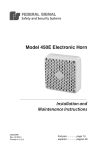
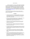
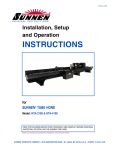
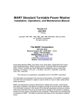
FEDERAL SIGNAL CORPORATION
EQUINOX
ELECTRO-MECHANICAL SIREN
INSTALLATION AND OPERATING INSTRUCTIONS
Copyright 2011 Federal Signal Corporation
255391C
7/11
IMPORTANT NOTICE
Federal Signal reserves the right to make changes to devices and
specifications detailed in the manual at any time in order to improve
reliability, function or design. The information in this book has been
carefully checked and is believed to be accurate; however, no
responsibility is assumed for any inaccuracies.
i
SAFETY NOTICES
People’s lives depend on your selection of suitable equipment and installation sites and your
safe installation, service, and operation of our products. Federal Signal recommends the following
publications from the Federal Emergency Management Agency for assistance with planning an
outdoor warning system: 1. The “Outdoor Warning Guide” (CPG 1-17), 2. “Civil Preparedness,
Principles of Warning” (CPG 1-14), 3. FEMA-REP-1, Appendix 3 (Nuclear Plant Guideline) and 4.
FEMA-REP-10 (Nuclear Plant Guideline). Contact Federal Warning System’s Customer Care
Center at: http://www.alertnotification.com or 1-800-524-3021 for further information about these
publications.
It is important to read, understand and follow all instructions shipped with this product. In addition,
listed below are some other important safety instructions and precautions you should follow.
PLANNING
If suitable warning equipment is not selected, the installation site for the siren is not selected
properly or the siren is not installed properly, it may not produce the intended optimum audible
warning. Follow Federal Emergency Management Agency (FEMA) recommendations.
If sirens are not activated in a timely manner when an emergency condition exists, they cannot
provide the intended audible warning. It is imperative that knowledgeable people, who are
provided with the necessary information, are available at all times to authorize the activation of
the sirens.
When sirens are used out of doors, people indoors may not be able to hear the warning
signals. Separate warning devices or procedures may be needed to effectively warn people
indoors.
The sound output of sirens is capable of causing permanent hearing damage. To prevent
excessive exposure, carefully plan siren placement, post warnings, and restrict access to
areas near sirens.
Activating the sirens may not result in people taking the desired actions if those to be warned
are not properly trained about the meaning of siren sounds. Siren users should follow FEMA
recommendations and instruct those to be warned of correct actions to be taken.
A siren out of order will not provide any warning. After installation, service, or maintenance,
test the siren system to confirm that it is operating properly. Test the system regularly to
confirm that it will be operational in an emergency.
If future service and operating personnel do not have these instructions to refer to, the siren
system may not provide the intended audible warning. Service personnel may be exposed to
death, permanent hearing loss, or other bodily injury. File these instructions in a safe place
and refer to them periodically. Give a copy of these instructions to new recruits and trainees.
Also, give a copy to anyone who is going to service or repair the siren.
ii
SAFETY NOTICES
People’s lives depend on your safe installation, service and operation of our products. It is
important to read, understand and follow all instructions shipped with this product. In addition,
listed below are some other important safety instructions and precautions you should follow:
INSTALLATION & SERVICE
Electrocution or severe personal injury can occur when performing various installation and
service functions such as making electrical connections, drilling holes, or lifting equipment.
Therefore experienced electricians in accordance with national, state and any other electrical
codes having jurisdiction should perform installation. All work should be performed under the
direction of the installation or service crew safety foreman.
The sound output of sirens is capable of causing permanent hearing damage. To prevent
excessive exposure, carefully plan siren placement, post warnings and restrict access to areas
near the sirens. Sirens may be operated from remote control points. Whenever possible,
disconnect all siren power including batteries before working near the siren.
After installation or service, test the siren system to confirm that it is operating properly. Test
the system regularly to confirm that it will be operational in an emergency.
If future service personnel do not have these warnings and all other instructions shipped with
the equipment to refer to, the siren system may not provide the intended audible warning and
service personnel may be exposed to death, permanent hearing loss, or other bodily injury.
File these instructions in a safe place and refer to them periodically. Give a copy of these
instructions to new recruits and trainees. Also, give a copy to anyone who is going to service
or repair the sirens. For additional copies, call the Federal Warning Systems Customer Care
Center at 800-524-3021 or write to them at 2645 Federal Signal Drive, University Park, IL
60484.
OPERATION
Failure to understand the capabilities and limitations of your siren system could result in
permanent hearing loss, other serious injuries or death to persons too close to the sirens when
you activate them or to those you need to warn. Carefully read and thoroughly understand all
safety notices in this manual and all operations-related-items in all instruction manuals shipped
with equipment. Thoroughly discuss all contingency plans with those responsible for warning
people in your community, company, or jurisdiction.
iii
Limited Warranty
The Federal Warning Systems Division of Federal Signal Corporation warrants each
new product to be free from defects in material and workmanship, under normal use and
service, for a period of two years on parts replacement and factory-performed labor (one
year for Informer, EAS, and Federal software products) from the date of delivery to the
first user-purchaser. Federal Warning Systems warrants every 2001 & Eclipse Siren
(Top of pole only) to be free from defects in material, per our standard warranty, under
normal use and service for a period of five years on parts replacement.
During this warranty period, the obligation of Federal is limited to repairing or replacing,
as Federal may elect, any part or parts of such product which after examination by
Federal discloses to be defective in material and/or workmanship.
Federal will provide warranty for any unit which is delivered, transported prepaid, to the
Federal factory or designated authorized warranty service center for examination and
such examination reveals a defect in material and/or workmanship.
This warranty does not cover travel expenses, the cost of specialized equipment for
gaining access to the product, or labor changes for removal and re-installation of the
product. The Federal Signal Corporation warranty shall not apply to components or
accessories that have a separate warranty by the original manufacturer, such as, but not
limited to, batteries.
Federal will provide on-site warranty service during the first 60-days after the completion
of the installation, when Federal has provided a turn-key installation including
optimization and/or commissioning services.
This warranty does not extend to any unit which has been subjected to abuse, misuse,
improper installation or which has been inadequately maintained, nor to units which have
problems related to service or modification at any facility other than Federal factory or
authorized warranty service centers. Moreover, Federal shall have no liability with
respect to defects arising in Products through any cause other than ordinary use (such
as, for example, accident, fire, lightning, water damage, or other remaining acts of god).
THERE ARE NO OTHER WARRANTIES, EXPRESSED OR IMPLIED, INCLUDING BUT
NOT LIMITED TO, ANY IMPLIED WARRANTIES OF MERCHANTABILITY OR FITNESS
FOR A PARTICULAR PURPOSE. IN NO EVENT SHALL FEDERAL BE LIABLE FOR
ANY LOSS OF PROFITS OR ANY INDIRECT OR CONSEQUENTIAL DAMAGES
ARISING OUT OF ANY SUCH DEFECT IN MATERIAL WORKMANSHIP.
2645 Federal Signal Drive, University Park, IL 60484
Phone: (800) 524-3021 Fax: (708) 534-4865
Website: http://www.alertnotification.com
iv
WARNING
Read and understand the information contained
in this manual before attempting to install or
service the siren.
Pay careful attention to the following notices located on the equipment.
NOTICES – EXTERNALLY PLACED.
v
TABLE OF CONTENTS
Paragraph
Page
SECTION I - CHARACTERISTICS
1-1
1-2
1-3
1-4
Scope of this Manual .............................................................................
General ..................................................................................................
Siren Description ...................................................................................
Signal Description ..................................................................................
1
1
1
1
SECTION II - SPECIFICATIONS
2-1
Specifications ........................................................................................ 2
SECTION III - INSTALLATION
3-1
3-2
3-3
3-4
Siren Location ........................................................................................
Siren Installation ....................................................................................
Siren Wiring ...........................................................................................
Pre-operation Checkout .........................................................................
3
4
7
8
SECTION IV - SERVICE AND MAINTENANCE
4-1
4-2
4-3
General .................................................................................................. 9
Inspection .............................................................................................. 9
Corrective Maintenance ......................................................................... 10
vi
SECTION I
CHARACTERISTICS
the siren from a 208/220 or 240, optionally
480 VAC line.
Two motors are used to create the siren
signals. One motor rotates the siren
assembly. The second motor, which
produces the sound energy, is attached to a
stator with a rotor mounted on the motor
shaft concentric to the stator. The rotor and
stator each contain one row of ports. As the
motor rotates the rotor, air is drawn into the
rotor and passes through the rotor and stator
ports in pulses. These pulses are produced
when the rotor alternately opens and closes
the stator ports. The pulses of air produce
sound at a frequency (pitch) that is
dependent upon the rotational speed of the
motor and the number of ports in the rotorstator combination.
291343A
Figure 1-1. Model Equinox
1-4.
1-1.
SCOPE OF THIS MANUAL.
The Equinox siren is capable of
producing a steady signal and a wailing
signal. The steady signal is frequently used
as a Civil Defense “Alert” signal. The wailing
signal is often used as a Civil Defense
“Attack” signal. Any of the signals are
capable of being used for any desired
application. These signals are shown
graphically in Figure 1-2.
This service manual describes the
characteristics, specifications, installation,
controls/theory of operation, and service and
maintenance of the Federal Equinox siren.
1-2.
GENERAL.
Federal’s Equinox siren (Figure 1-1) is
an electro-mechanical, DC, rotating siren that
is capable of producing high intensity
warning signals over a large area. A highly
efficient design enables the siren to produce
a high sound level, while making moderate
demands on the power source.
1-3.
SIGNAL DESCRIPTION.
SIREN DESCRIPTION.
The Equinox siren is a single tone siren
capable of producing a 125 dB sound level at
100 feet for a minimum of 15 minutes, when
using the DCB series Control Unit/Battery
Box with fully charged, standard, deep-cycle,
marine batteries. 30-minute duty cycle
operation is available with option 2001TRB.
This option supplies DC current directly to
Figure 1-2. Signal Characteristics.
1
SECTION II
SPECIFICATIONS
Power Requirements*
Siren Motor .................................................. 48V (DC or full wave
rectified AC) 115 Amps (nom.)
Rotator Motor ............................................... 48V (DC or full wave
rectified AC) 1 Amp (nom.)
Wiring
Siren Motor .................................................. 2 AWG
Rotator Motor ............................................... 14 AWG
Motor Type
Siren ............................................................ Series Wound DC 6.5 Hp
Rotator......................................................... Permanent Magnet DC 1/8 Hp
Signal Information
Signal
Frequency Range
Sweep Rate
STEADY
WAIL
FAST WAIL
500 Hz
180 - 500Hz
300 - 500Hz
N.A.
10 sec.
3.6 sec.
Signal Duration ........................................... 3 min. (programmable)
Sound Output (SPL) ............................................... 125 dBC +/-1 dBC (on axis)
at 100' (30.5m.)
Rotation .................................................................. 3 RPM
Dimensions (HWD) ................................................. 62" x 37" x 41"
1574 mm x 940 mm x 1041 mm
Shipping Weight ..................................................... 460 pounds (209 kg.)
Siren Weight ........................................................... 350 pounds (159 kg.)
Operating Temperature .......................................... -30 C to +60 C **
* Power requirements refer to the power supplied by the batteries or optional AC operation
with battery back up.
** The siren can operate throughout this temperature range provided the battery temperature
is maintained at -18 C or higher.
2
SECTION III
INSTALLATION
accumulate. These losses are a result of
weather conditions, terrain, obstructions in
the sound path and vary with frequency.
DANGER
Electrocution or severe personal
injury can occur when making
electrical connections, drilling holes,
or lifting equipment. Therefore,
installation should be performed by
experienced
electricians
in
accordance with national and local
electrical codes.
3-1.
Optimum sound propagation conditions
exist when there are no obstructions in the
sound path, the terrain is flat, and the air is
calm and warm compared to the ground
temperature. Since these conditions are
rarely met, under typical outdoor conditions,
each time the distance from the siren is
doubled, the sound level decreases by
approximately 10 dB making it half as loud.
For example, if the sound level at 100 feet
(30.5 m) from an Equinox siren is 125 dB, at
200 feet (61 m), the level drops to 115 dB; at
400 feet (122 m) the sound level drops to
105 dB, etc. This is referred to as the “loss
per distance doubled”.
SIREN LOCATION.
The information in this section provides
guidelines to aid the user in the selection of
an installation site that makes the best
possible use of the siren.
WARNING
Experience has shown that a loss per
distance doubled of 10 dB is a generally
conservative loss factor that is applied to
outdoor sound propagation over long
distances under average conditions. Large
obstructions, wind, temperature gradients,
and terrain can significantly increase sound
loss to 12 or more dB per distance doubled.
An acoustic survey of the area using acoustic
modeling software is recommended to
optimize sound coverage.
The output level of an Equinox siren
is capable of causing permanent
hearing damage. To prevent
excessive exposure, carefully plan
the siren location and post warnings
where excessive levels may be
encountered. Refer to OSHA 29
CFR 1910.95 for safe exposure
limits.
Studies indicate that an individual with
normal hearing will probably hear a warning
signal whose intensity is at least as high as
the ambient noise level. FEMA guidelines
recommend 10 dB SPL above ambient for
warning system design to provide adequate
warning.
Careful consideration of the factors
affecting the propagation of sound from the
siren and the response of the human ear to
the sound will optimize the ability of the siren
to effectively warn the community. Follow
Federal Emergency Management Agency
(FEMA) guidelines when designing the
warning system.
FEMA lists ambient noise levels typically
encountered as follows:
Urban Residential areas = 60 dBC
Industrial Area = 70 dBC
Within 100’ of Busy Highways = 90 dBC
The reduction of signal intensity as the
distance from the siren increases and the
minimum desired signal level at the fringe of
the area to be covered are important
considerations when choosing a siren
installation site. As the distance from the
siren increases, sound level losses
Assuming a typical 10 dB loss per distance
doubled and a 70 dB minimum sound level
3
required to warn a typical urban area, the
effective range of the Equinox siren is
approximately 3200 feet.
above the ground. It is attached to the pole
by means of legs, as shown in Figure 3-2.
Wind speed and direction affect the
propagation of sound from the siren.
Consequently, the direction of the prevailing
wind may also be a factor to consider when
selecting the installation site(s) of a small,
one or two-siren system. For example, if the
prevailing wind is from the west, it may be
desirable to install the siren toward the
western edge of the area to be covered.
Other factors to consider before
selecting the installation site include the
availability of electrical power, the ease of
installation and maintenance, the height of
surrounding obstructions, and security
against vandalism.
3-2.
A.
SIREN INSTALLATION.
General.
Most siren installations are one of two
types: Pole Mount or Flat Surface Mount.
These two configurations make it possible to
install a siren in almost any situation. If the
installations in this paragraph are not
suitable, modification of one of the
configurations may be practical.
A siren is typically installed 40 - 50 ft.
above the ground. If the installation is located
less than 40 ft. above the ground, the sound
intensity at close range may increase, but at
the same time the effective range of the siren
may be reduced. Conversely, if the siren is
located more than 50 ft. above ground, the
effective range of the siren may increase, but
the sound may skip over areas closer to the
siren. These variables may make it desirable
to test the sound coverage of the siren at
various heights and locations whenever
possible.
B.
Pole Mounting.
Figure 3-1. Typical Pole-mounted Installation
A typical siren pole-mounted installation
is shown in Figure 3-1. The siren is mounted
on a Southern Yellow Pine, Douglas Fir or
equivalent Class 2 utility pole 40 - 50 ft.
4
SIREN
BASE PLATE
3. Erect the utility pole in accordance with
accepted practices. Be sure the pole extends
at least 40 ft. above the ground (refer to
WARNING above).
LEGS (4)
SEE DETAIL
BELOW
4. Raise the siren to the necessary height,
and lower it over the pole.
5. Adjust the legs and insert shims, if
necessary, between the siren legs and pole.
The legs adjust to a diameter between 7.53”
and 12.25” (See Figure 3-3). Bolt the siren to
the pole using two 5/8" galvanized lag bolts
with washers and split lockwashers per leg.
At least four inches of lag bolt must be
screwed into the pole. Tighten all bolts.
1/2-13 HEX NUTS (8)
SPLIT LOCKWASHERS (8)
1/2-13 HEX HD. BOLTS (8)
LEGS (4)
291307B
Figure 3-2. Siren Leg Assembly.
Using the 3 ft. long angle iron legs, the
siren is mounted on the Class 2 utility pole as
follows:
1. Uncrate the siren and remove the nuts
that hold the siren on the shipping base. Lift
the siren approximately 3-1/2 ft. with a crane
or hoist.
2. Install the four legs on the siren
mounting plate, as shown in Figure 3-2. Use
two 1/2" bolts, nuts and lockwashers
(provided) for each leg. Do not tighten the
bolts completely.
Figure 3-3. Leg Assembly Diameters.
C. Flat Surface Mount.
This installation configuration is practical
when the installation site is on a flat roofed
building. The siren can be anchored directly
to the roof, on a platform as shown in Figure
3-4, or on a weight distribution mat like the
one shown in Figure 3-5.
WARNING
The lifting bracket does NOT have
sufficient strength to support the
combined weight of the siren and a
utility pole. Therefore, do NOT
attempt to erect the pole and siren
together using the bracket as a
lifting point.
This mat is required when the siren
mounting surface is unable to support over
176 pounds per square foot (859 kg per
square meter). The mat shown in Figure 3-4
5
distributes the siren weight to approximately
25 pounds per square foot (122 kg per
square meter). When installing the siren on a
flat roof, be sure that it clears the parapets or
other obstructions by at least ten feet.
To install an Equinox on a flat roof or other
flat surface, proceed as follows:
1. If desired, construct a platform for
mounting the siren, which must be capable of
supporting at least 435 lbs. (197 kg.) as well
as withstanding a siren wind load of 100
mph. The platform must also be capable of
distributing its own weight plus the siren to a
value that is safe for the mounting surface.
Platform design and construction details
should be designed by a structural engineer
familiar with the building construction of the
intended install location. Locate the platform
at the siren installation site. The platform
must be properly anchored to the mounting
surface.
WARNING
The hoisting bracket does not have
sufficient strength to support the
combined weight of the siren and a
platform. Therefore, do NOT lift the
siren and platform together using
the bracket as a lifting point.
2. Hoist the siren to the installation site
using the lift bracket as a lifting point (refer to
WARNING above).
3. Anchor the siren to the mounting surface
with 1/2" lag bolts or nuts and bolts, as
appropriate through the mounting holes (one
in each corner) in the siren base plate (see
Figure 3-4, detail A). If the siren is mounted
directly on a roof, (without a platform or
weight distribution mat) be sure to install
waterproof joints at the points where the
mounting bolts pass through the roof so that
water does not enter the building.
Figure 3-4. Typical Surface-mounted Siren Installation
6
Figure 3-5. Weight Distribution Mat Construction
3-3.
SIREN WIRING.
The Equinox is pre-drilled on two sides
for connecting a 1” conduit to either side. The
siren enclosure is rain tight. To maximize the
longevity of the siren, rigid watertight conduit
connections are recommended between the
Equinox and the controller.
Three wires are required to operate the
Equinox. One #2 AWG red wire from the 48
VDC chopper control contactor output of the
controller provides positive power to the
chopper motor. One #12 AWG red wire from
the rotator control contactor output of the
controller provides positive power to the
rotator motor. One #2 AWG black wire
provides a common 48 VDC negative ground
between the ground plane of the control
cabinet and siren motors. See Figure 3-6 for
the wire connections in the Equinox. Consult
the manual for the controller being utilized to
connect the wires from the head.
Figure 3-6. Wiring for Rotator Motor
All wire connections should be treated
with anti-oxidant to prevent corrosion from
moisture and natural processes. Care should
be taken to insure that all wire connections
are firmly tightened. To properly tighten the
wire connections in the terminal block, insert
the wire, firmly tighten the setscrew, move
the wires to loosen and repeat the process
until the wires are securely tightened.
7
3-4.
PRE-OPERATION CHECKOUT.
After the siren has been completely
installed, perform the following checks before
putting the siren into service.
A.
Make sure that all air intakes and sound
outlets are not obstructed.
B.
Make sure all connections in the Control
Unit/Battery Box are correct and
properly tightened.
C.
Activate all siren tones to verify they are
operating properly. The siren should
remain rotating during all alert tones.
D.
After the installation is complete and it
has been established that the siren is
operating properly, Federal recommends
that all control devices be padlocked to
discourage tampering and vandalism.
WARNING
The output sound level of a siren is
capable of causing severe hearing
discomfort or permanent hearing
damage. Therefore, ALWAYS wear
hearing protection when performing
tests or maintenance on the siren.
8
SECTION IV
SERVICE
4-1.
GENERAL.
Box before inspecting or maintaining the
siren.
DANGER
4-2.
Service should be performed by
qualified personnel familiar with the
siren, associated controls, and
power sources being used. The
siren has moving parts, high
operating currents, explosive gases,
and corrosive materials that could
cause severe personal injury,
electrocution, or death. Before
servicing or maintaining, ensure that
remote activation cannot occur and
disconnect power to the siren and its
controls.
INSPECTION.
Test the Equinox siren for proper
operation at least once a month. A daily test
at noon, curfew, or other selected time is
preferred. This not only enhances the
usefulness of the siren, but also instills public
confidence in the reliability of the warning
system.
In order to minimize the possibility of
siren failure, annual inspection and
maintenance
is
desirable.
Battery
replacement
should
be
performed
approximately every five years. This
schedule is only a suggested guideline. It
may be necessary to vary the schedule if the
siren is used frequently or if it is used in an
extreme climate.
Experience has shown that all Federal
sirens are highly reliable devices. However, if
a siren failure does occur, Federal will
provide technical assistance with problems
that cannot be handled satisfactorily and
promptly locally. If assistance is desired,
contact:
A.
Turn off the power to the siren at the
disconnect switch. Disconnect the 48
VDC, 4 AWG red wire in the Control
Unit.
B.
Inspect the siren installation to be sure
that it is vertically oriented. Take
corrective action if a pole-mounted
installation is more than 5º from vertical
or if a roof or flat surface mount is more
than 10º from vertical. This will prevent
lubrication losses and excessive motor
bearing wear.
The output sound level of an
Equinox siren is capable of causing
permanent
hearing
damage.
Therefore, ALWAYS wear hearing
protection when performing tests or
maintenance on the siren.
C.
Inspect all electrical and mechanical
connections. Make sure that all
fasteners are properly tightened.
D.
Inspect all painted surfaces and repaint
as necessary.
To prevent the siren from sounding or
rotating, always turn off the power to the
siren at the disconnect switch and remove
the 48 VDC, 4 AWG red wire in the Battery
E.
Both the rotator motor and siren motor
have
sealed
and
pre-lubricated
bearings. Therefore, neither of these
motors
requires
any
additional
lubrication.
FWS Customer Care Center
Signal Division
Federal Signal Corporation
2645 Federal Signal Drive
University Park, Illinois 60484
800-524-3021
WARNING
9
4-3.
scale indication should decrease to
some force within the specified range. If
the scale does not indicate between 25
and 30 pounds (11 and 13 kg.), the drive
band requires adjustment.
CORRECTIVE MAINTENANCE.
This section includes illustrations that
may be helpful if the siren or rotator needs
repair.
2.
To adjust the drive band:
(a). Perform steps (a)., (b)., and (c). in
paragraph 4-3., A.1. (left) to determine if
a drive band adjustment is necessary.
WARNING
To prevent siren from sounding or
rotating, always turn off power at the
disconnect switch and disconnect
the 48VDC, 4 AWG red wire in the
Control Unit before performing any
maintenance on the siren.
A.
Drive Band Adjustment.
1.
When
the
drive
band
requires
adjustment, tightening is almost always
necessary. To determine if a drive band
adjustment is required:
(b). Ensure that power to the siren is
disconnected.
(c). Remove the panel opposite the conduit
fitting on the rotator housing.
(d). Tighten the cross bolt with the spring
one or two turns (see Figure 4-2). DO
NOT tighten or loosen the cross bolt
without the spring. Attach the scale to
the horn and pull on the scale to rotate
the horn. If the scale does not indicate
between 25 and 30 pounds (11 and 13
kg.), repeat this step until the scale
indicates the proper force.
(a). Turn off power to the siren at the
disconnect switch. Remove the 48 VDC,
4 AWG red wire in the Control Unit.
PINION GEAR
SPRING
(b). Attach a spring scale having a capacity
of at least 50 pounds (22 kg.) to the horn
of the siren as shown in Figure 4-1.
SPUR GEAR
ROTATOR
GEARMOTOR
TERMINAL
BLOCK
120
100
80
60
40
20
0
SIDE
PANELS
291300A
291301A
Figure 4-2. Rotator Assembly Interior
Figure 4-1. Spring Scale Attachment to Siren.
CAUTION
(c). Pull on the scale until the horn begins to
rotate. Continue to rotate the horn by
pulling on the scale while reading the
scale. The scale should indicate
between 25 to 30 pounds (11 and 13
kg.). It may require more than 40 pounds
of force to start the horn moving.
However, after the horn is moving, the
If the cross bolt with the spring is
tightened so that more than 40
pounds (18kg.) of pull is necessary
to maintain manual horn rotation,
high winds may cause damage to
the rotator drive mechanism.
10
4.
(e). Replace the
housing.
panel
on
the
rotator
B.
Collector Ring Brush Replacement.
1.
Remove the cover from the top of the
collector housing.
Remove lead wire from brush holder.
Remove the worn brush from the brush
holder in the brush holder plate. (See
Figure 4-5).
COVER
PLUG
WIRES
BRUSH
HOLDER
BRUSH
291304C
Figure 4-5. Brush Holder Assy.
5.
Insert the replacement brush into the
brush holder. Connect the lead wires to
the brush holder.
C.
Collector Ring Removal.
1.
Remove the brush
described above.
2.
Disconnect the three wires from the
terminal block (TB5) inside the rotator
housing and begin feeding wires up into
the siren shaft (see Figure 4-2).
3.
Federal suggests that the rotator drive
band be loosened, as described in
paragraph 4-4.B., to rotate the siren
during removal of the collector ringbolts.
291302C
Figure 4-3. Collector Ring Housing
2.
3.
Note the wiring location before removing
the wires. (See Figure 4-3).
Remove the four bolts on the side of the
collector housing assembly (see Figure
4-4) and remove the brush assembly.
Note: Press down on brush assembly
while removing the four bolts. Brush
assembly is under spring tension while
in position.
BRUSH
ASSEMBLY
assembly
as
CAUTION
To prevent damage to the cover
assembly, use a piece of wire to secure
the cover in an open position before
removing the housing’s back panel.
TERMINAL
BLOCK
BOLTS(4)
PLUG
291303D
4.
Remove the back panel to expose the
small plug on the collector housing
assembly.
5.
Remove the small plug.
6. Manually rotate the siren and remove
each of the four bolts that hold in the
collector rings (see Figure 4-7). Access to
Figure 4-4. Installation/Removal Brush Assy.
11
these bolts can be gained through the
plug opening.
13. Replace the plug on the collector
housing assembly.
14. Replace the back panel.
PLUG OPENING
STAND-OFF
D.
Rotator Motor Replacement.
1.
Remove the two rotator housing panels
(see Figure 4-2).
2.
Replace
the
rotator
motor.
Approximately a 1/64” gap between the
teeth of the two gears is required to
avoid binding. Re-tighten rotator motor
bolts to a torque of 45 in. lbs.
3.
Wire rotator motor and terminal block as
shown in Figure 3-6.
291305B
REMOVE BOLT(4)
Figure 4-7. Collector Housing Opening
7. Remove the collector rings with standoffs and cables still attached (see Figure
4-8).
4. Grease all gear surfaces with Mobil
Mobilith SHC lithium based grease.
8. Reassemble the collector rings, standoffs, and cables before reinstallation.
5. Replace housing panels.
BOLTS/STAND-OFFS(4)
COLLECTOR RINGS
E.
Siren Motor Brush Replacement.
1.
Remove the outer cone. Remove the
inner cone by removing the four 1/4-20
bolts which secure the cone to the four
internal mounting brackets (8402087E01).
2.
Note siren motor wiring and remove both
terminal connectors.
3.
Remove steel mesh brush covers from
motor.
Figure 4-8. Collector Rings
4.
Replace worn brushes.
9. To replace collector ring assembly, align
the stand-offs before replacing the four
bolts removed in step seven above.
5.
Replace steel mesh brush covers.
6.
Replace
terminal
connectors,
lockwashers, and nuts. Tighten nuts.
7.
Replace inner and outer cones.
PLUG
OPENING
291306B
10. Ensure
that
collector
rings
are
concentrically aligned before replacing
the brush assembly.
11. Replace the brush assembly.
12. Look through the plug opening and
ensure that brushes are contacting the
proper collector rings.
12
Figure 4-9. Equinox Final Assembly, Sheet 1
13
Figure 4-10. Equinox Final Assembly, Sheet 2
14