1
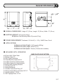
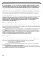
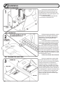
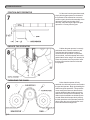
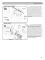
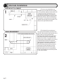
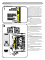
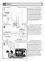
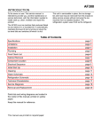
For Classes I, II, III, IV pg 1 Contents Pg. General Information.................................................................................................................3 Features...................................................................................................................................5 Parts Identification...................................................................................................................6 Installation................................................................................................................................8 Alternate Installation..............................................................................................................12 Electrical................................................................................................................................13 Fine Tuning............................................................................................................................17 Master and Slave...................................................................................................................18 Wiring Diagrams....................................................................................................................19 Safety Edge and Warning Placards.......................................................................................21 Options..................................................................................................................................23 Maintenance and Safety........................................................................................................25 Trouble Shooting....................................................................................................................26 IMPORTANT SAFETY INSTRUCTIONS WARNING - To reduce the risk of injury or death: 1) READ AND FOLLOW ALL INSTRUCTIONS 2) Never let children operate or play with gate controls. Keep the remote control away from children. 3) Always keep people and objects away from the gate. NO ONE SHOULD CROSS THE PATH OF THE MOVING GATE. 4) Test the gate operator monthly. The gate MUST reverse on contact with a rigid object or stop when an object activates the non-contact sensors. After adjusting the force or the limit of travel, re-test the gate operator. Failure to adjust and re-test the gate operator properly can increase the risk of injury or death. 5) Use the emergency release only when the gate is not moving. 6) KEEP GATES PROPERLY MAINTAINED. Read the owner's manual. Have a qualified service person make repairs to gate hardware. 7) The entrance is for vehicles only. Pedestrians must use separate entrance. 8) SAVE THESE INSTRUCTIONS. pg 2 General Information OVERALL DIMENSIONS: Height: 21" (53 cm) Length: 12" (30 cm) Width: 17" (43 cm) SHIPPING WEIGHT: 140 pounds (64 kg) z Options: Steel Mounting Stand: 23 pounds (10 kg) POWER REQUIREMENT: Dedicated 115 Volt AC (+/- 10V), 5 AMP Power Circuit APPLICATIONS: z Maximum Gate Weight: 1,500 pounds (680 kg) z Maximum Gate Length: 40 feet (12 m) z Maximum Gate Speed: 10in/sec (12in/sec also available) INCLUDED WITH OPERATOR: BASE PLATE HOLE PATTERN z 40-Feet of # 41 Roller Chain z 2-Master Links # 41 z 2-Zinc Plated Chain Bolts z 2-Chain Brackets, Right and Left z 2-U-Bolts, Round (for chain brackets) z 2-U-Bolts, Square (for chain brackets) z 2-Safety Safety Warning Placards z 1-Hex Wrench 5/16" z 1-Instruction Manual z 1-Flexible Conduit End Fitting 1/2" z 4-Sleeve Anchor Bolts (red heads) 3/8" X 3" z 1-Hex Bolt with Nut, 1/4"-20 z 1-Self Tapping Screw, 1/4"-20 pg 3 General Information continued... CIRCUIT BOARD: The AGS 3000 uses the Full Systems Capability circuit board, a powerful control system which is used on many other AGS gate operators. This circuit board operates on 12 ~ 18 Volts and can deliver power to the motor through high power external switching. The limit switch input terminals require the use of normally open type limit switches. These switches are used to accurately stop the gate operator in the open and closed positions. To safeguard the operator from damage that could result from limit switch or gate sensitivity failure, the Full Systems Capability circuit board has a built-in maximum run timer which will allow the operator to run for approximately 40 seconds and then shut off automatically. The Full Systems Capability circuit board has an adjustable gate sensitivity feature which will stop or reverse the gate if the gate is pushing harder than normal because of an obstruction. GATE SENSITIVITY: The AGS 3000 Full Systems Capability circuit board has a built-in safety feature which when adjusted properly will deliver only enough power to the motor to overcome the resistance of the gate. The amount of power that the circuit board will deliver can be adjusted for both directions of travel to accommodate the various gate weights that the AGS 3000 operator is recommended for. (See Applications Pg. 3) Vehicular Gate Operator Classes: Class I - Residential Vehicular Gate Operator: A vehicular gate operator (or system) intended for use in a home of one-to four single family dwelling, or a garage or parking area associated therewith. Class II - Commercial/General Access Vehicular Gate Operator: A vehicular gate operator (or system) intended for use in a commercial location or building such as a multi-family housing unit (five or more single family units), hotel, garages, retail store, or other building servicing the general public. Class III - Industrial/Limited Access Vehicular Gate Operator: A vehicular gate operator (or system) intended for use in an industrial location or building such as a factory or loading dock area or other locations not intended to service the general public. Class IV - Restricted Access Vehicular Gate Operator: A vehicular gate operator (or system) intended for use in a guarded industrial location or building such as an airport security area or other restricted access location not servicing the general public, in which unauthorized access is prevented via supervision by security personnel. Gate Operator model AGS2000 is intended for Vehicular Gate Operator Classes I, II, III, and IV. Gate Inspection: a) Install the gate operator only when: 1) The operator is appropriate for the construction of the gate and the usage Class of the gate, 2) All openings of a horizontal slide gate are guarded or screened from the bottom of the gate to a minimum of 4 feet (1.2 m) above the ground to prevent a 2-1/4 inch (57.15 mm) diameter sphere from passing through the openings anywhere in the gate, and in that portion of the adjacent fence that the gate covers in the open position. 3) All exposed pinch points are eliminated or guarded, and 4) Guarding is supplied for exposed rollers. b) The operator is intended for installation only on gates used for vehicles. Pedestrians must be supplied with a separate access opening. c) The gate must be installed in a location so that enough clearance is supplied between the gate and adjacent structures then opening and closing to reduce the risk of entrapment. d) The gate must be properly installed and work freely in both directions prior to the installation of the gate operator. Do not over-adjust the gate sensitivity to compensate for a damaged gate. pg 4 Features OPERATION The AGS 3000 Full Systems Capability can operate in a AUTO CLOSE TIMER (TIMER ON) or a PUSH-TO-OPEN/PUSH-TO-CLOSE (TIMER OFF) mode of operation. In the AUTO CLOSE TIMER mode of operation the operator is given a command to open the gate and hold it open until the input is released and until the auto close timer has elapsed at which point the operator will close the gate automatically. In the PUSH-TO-OPEN/PUSH-TO-CLOSE mode of operation each time a signal is sent to the operator, it will cause it to do the opposite of what it did before. (i.e., If the gate is closed, it will start opening, if it is open, it will start closing: If it is closing, it will REVERSE TO OPEN, if it is opening, it will REVERSE TO CLOSE.) CONTROLS The AGS 3000 Full Systems Capability works with the following control devices: Radio transmitters and their receiver (specified by and available from the manufacturer). Key switches, Push buttons (separate or intercom), numerical key pads and any peripheral equipment which can supply normally open or normally closed contacts. These contacts can be connected to the operator input terminals to perform the opening, close, safety, or the stop functions. AUTO CLOSE TIMER The operator comes factory preset with the auto close timer turned OFF. The auto close timer will close the gate automatically after a specific amount of time has elapsed. The amount of time can be easily adjusted between 0 and 45 seconds by turning a small "pot" located on the right edge of the circuit board (See page 17). The timer can be disabled or activated by flipping a single switch located on the top right edge of the circuit board. If the timer will be used it is recommended that some type of supplementary safety device be installed. If more time is required, there is an extended timer available from the manufacturer allowing up to 100 min. MANUAL RELEASE SWITCH This simple on-off switch is built into the operator. In an emergency, EVEN WITH THE POWER OFF, the gate can be pushed open manually after flipping the switch from Operate to Release. GATE SENSITIVITY ADJUSTMENT The amount of force necessary to stop the gate can be adjusted to conform to the various sizes and weights of any particular gate. When adjusting the sensitivity, the operator can be given only as much energy as is necessary to overcome the resistance of the gate. If the gate should strike an obstruction in either direction, the gate will reverse. If the gate should again strike an obstruction before reaching a limit, the gate will stop, remain stopped, and will sound an alarm. (See page 17) MASTER AND SLAVE Some very large entrances may require the use of two gates. If this is the case, the two gates can be easily automated using the "master and slave" configuration. This configuration uses two gates and two operators in ONE driveway. The operators used are two regular AGS 3000 Full Systems Capability operators one of which is of standard "right hand operation" and the other which is easily converted to "left hand operation" by flipping a single switch located at the top of the circuit board. (See page 17.) pg 5 Parts Identification pg 6 Parts Identification continued... PART # QNTY. 001 002 003 004 005 006 007 008 009 010 011 012 013 014 015 016 017 018 019 020 021 022 023 024 025 026 027 028 029 030 031 032 033 034 035 036 037 038 039 040 041 042 043 044 045 046 047 048 049 050 051 052 053 054 055 056 057 058 059 060 1 2 4 4 2 2 1 1 1 1 1 1 1 1 1 1 1 1 1 1 2 2 2 0 1 2 1 0 0 2 1 1 1 1 2 1 1 1 2 1 1 4 4 1 1 1 1 1 1 1 1 1 1 1 2 2 2 1 2 4 QNTY. ALLEN WRENCH FOR COVER, 5/16" HEX KEY BEARING, SELF ALIGNING, 1" BORE BOLT, 3/8"-16 X 1", SOCKET HEAD CAP BOLT, SLEAVE ANCHOR, 3/8" X 3" BRIDGE RECTIFIER, 35 AMP CHAIN BRACKET ANGLE, RIGHT AND LEFT CHAIN, #41, 40 FT CIRCUIT BOARD, FULL SYSTEMS CAPABILITY CIRCUIT BREAKER RESET BUTTON, 5 AMP COVER, LARGE METAL FOR OPERATOR COVER, PLEXI GLASS FOR CIRCUIT BOARD DRIVE SHAFT 1" WITH THREADED BODY FITTING, 90 DEGREE FOR FLEX CONDUIT FITTING, STRAIGHT FOR FLEX CONDUIT FRAME SUBSTRATE GEAR BOX SPEED REDUCER, ON MOTOR HANDY BOX FOR 115 VOLT RECEPTACLE HANDY BOX RECEPTACLE COVER PLATE IDLER PLATE, FOR MOUNTING SPROCKETS LIMIT GUIDE PLATE COMPRESSION SPRING FOR GUIDE PLATE LIMIT NUT LIMIT SWITCH LIMIT SWITCH ASSEMBLY LIMIT SWITCH MOUNTING PLATE MASTER LINK #41 MOTOR, 1/2 HP, 90VDC OPTION, SPACE SAVER FOR REAR MOUNT OPTION, STEEL MOUNTING STAND PLATE, SIDE, RIGHT AND LEFT POWER CORD "PIG TAIL" RECEPTACLE, 115 VOLT DUPLEX RELAY HOUSING BASE RELAY HOUSING COVER RELAY, 12 VOLT DC RESISTOR, BALLAST, 10 OHM SIGN, METAL CAUTION SPROCKET, DRIVE #41, 1" BORE, 41B20 SPROCKET, IDLER #41, 3/4" BORE, 41B24 SPROCKET, LARGE GEAR REDUCTION 41B54 SPROCKET, SMALL GEAR REDUCTION ON MOTOR STANDOFF, 1" ALUMINUM, M/F, FOR PLEXI GLASS STANDOFF, 1/2" ALUMINUM, F/F, FOR CIRCUIT BOARD STICKER, AGS 3000 STICKER, AGS MANUFACTURING STICKER, CAUTION STICKER, MANUAL RELEASE STICKER, ON/OFF BREAKER STICKER, PATENT STRAIN RELEIF CONNECTOR FOR PIG TAIL SWITCH, MANUAL RELEASE SWITCH, POWER ON/OFF TOGGLE TRANSFORMER, 18 VOLT TRANSFORMER, 70 VOLT U-BOLT, ROUND U-BOLT, SQUARE BOLT, HEX HEAD 5/16"-18 X 3/4" WASHER, SPLIT RING 5/16" ID SCREW, 8-32 X 1" SOCKET HEAD CAP SCREW, 6-32 X 3/8" PAN HEAD PHILLUPS PART # QNTY. 061 062 063 064 065 066 067 068 069 070 071 072 073 074 075 076 077 078 079 080 081 082 083 084 085 086 087 088 089 090 091 092 093 094 095 096 097 098 099 100 101 102 103 104 105 106 107 108 109 110 111 112 113 114 115 116 117 118 119 120 4 4 2 4 4 7 20 7 2 2 1 2 4 4 4 2 4 1 1 QNTY. WASHER, 3/8" ID, STAINLESS NUT, JAM STYLE WASHER, SPLIT RING 5/8" ID SCREW, SOCKET HEAD CAP LOCK NUT SCREW, SOCKET HEAD CAP 3/8"-16 FLAT WASHER, 3/8" ID SCREW, SOCKET HEAD CAP BOLT, HEX HEAD BUSHING, BRONZE KEY, 3/16" SCREW, SOCKET HEAD CAP WASHER, FLAT 3/16" ID BOLT, HEX HEAD 3/8"-16 WASHER, SPLIT RING 3/8" ID KEY, WOODRUF 1/4" SCREW, PAN HEAD PHILLUPS POWER CORD (PIG TAIL) RECEIVER (OPTIONAL) pg 7 Installation INSPECT PACKAGING Remove the gate operator from it's package and make sure that all parts are included. Refer to General Information and Parts Identification. If any parts appear to be missing, contact a dealer. Temporarily plug the operator into 115 Volt outlet or extension cord. TEST OPERATOR Before beginning installation, test the gate operator by running the operator back and fourth 2 or 3 times. If the gate operator appears to have any shipping damage, contact a dealer. If the gate operator is equipped with radio controls, the operator may be run back and fourth by pressing the radio transmitter. If the gate operator is not equipped with radio controls, the operator may be run back and fourth by momentarily touching the open input terminals together. The terminals can be touched together with a short length of wire, paper clip or needle nose pliers. For the full systems capability circuit board, the open input terminals are 5 and 6. Disconnect Power when finished! SET TRANSMITTER SWITCHES Now is a good time to set the radio transmitter and receiver to a unique setting. All units come from the factory with identical settings and therefore it is advisable to change the setting. To change the switch setting, simply set the switches in the radio receiver (using a paper clip or similar) to any arbitrary setting and then set the switches in the transmitter/s to match the switches in the receiver. The battery in the transmitter may last 1 to 2 years. Be sure to replace the battery only with one that is the same type as the original (9 Volt). pg 8 Installation continued... GATE PREPERATION CEMENT PAD LOCATION Disconnect Power from the gate operator! The tail end of the gate should extend approximately 24" beyond the edge of the driveway. If this is not the case, an extension tail will need to be added to the gate. This will give room for the gate operator. Make the extension tail 24" X 24" as shown. If the gate has not yet been fabricated, add 24" to the length of the gate. If no concrete surface exists to attach the gate operator to, make a cement pad 16" X 24" X 10" (4" above ground). Place the shortest pad edge even with the driveway edge. Place the longer edge of the pad 1" away from the gate. OPTIONAL MOUNTING STAND If the steel mounting stand will be used, place the shortest edge of the stand 4" from the driveway edge and place the longest edge of the stand 4-1/2" away from the gate. The top of the steel stand may sit on the ground or the stand may be elevated to keep the operator above snow, flooding etc. Make a post hole and cement the stand in place, making sure the stand is level and square to the gate. pg 9 Installation Continued... POSITION GATE OPERATOR If the steel mounting stand was used, simply bolt the gate operator to the stand. If the operator will be mounted to a concrete surface or pad, place the shortest edge of the operator 4" away from the edge of the driveway. Place the longer edge of the gate operator 2-1/2" away from the gate. ANCHOR THE OPERATOR When the gate operator is correctly positioned on the concrete surface or pad, mark the base hole locations onto the cement with a felt tip marker or equivalent. Once marked, move the operator to the side and drill the 4 holes using a 3/8" masonry bit. Place the operator back into position. Insert the four sleeve anchors into the holes and firmly tighten. THREADING THE CHAIN Now that the operator is firmly attached, the chain may now be connected to the gate and operator. Begin by threading the chain through the sprockets. The sprockets come arranged as shown so that the chain may be threaded under the idler sprockets and over the drive sprocket. Alternately, the chain may be threaded over the idler sprockets and under the drive sprocket by moving the idler sprockets to the alternate positions above. Note: the cover will need to be modified for the alternate arrangement. pg 10 Installation Continued... ATTACH CHAIN TO GATE Attach the gate bracket to the gate as shown using the round or square u-bolts for round or square gate frames respectively. Attach the chain to the gate brackets using the chain bolt and master link as shown. If necessary, the chain may be easily shortened using a chain breaker. Adjust the height of the gate brackets until the chain is level and firmly tighten the u-bolts. For round gate frames it may be necessary to drive the self tapping screw through the gate bracket, and into the gate. ADJUST LIMITS The limit nuts need to be adjusted to cause the gate to stop in the desired open and closed positions. These adjustments can be roughly made before power has been hooked up by flipping the manual release switch and pushing the gate manually. Push the gate to the open position and adjust the limit nut to press the limit switch in. The limit nuts can be turned after pressing down on the guide plate. Push the gate closed and adjust the other limit nut to press in the other limit switch. Caution "do not allow the limit nuts to travel past the switch as this may damage the switches". When finished, make sure the guide plate is properly engaged with the grooves on the limit nuts. pg 11 Alternate Installations REAR MOUNT PLACEMENT CHAIN ARRANGEMENT pg 12 The rear mount installation is an excellent way to conceal the chain or operator. The operator is placed in the extreme rear of the gate as shown and the chain never goes across the driveway. The chain only goes from the gate operator to a post or wall beside the driveway. Place shortest edge of the operator 3" from the rear end of the gate and place the long edge of the operator 3-1/2" away from the gate toward the wall. The chain will form a continuous loop, going around the drive sprocket on the operator, and around the idler sprocket on the post or wall. Only one gate bracket is required on the rear edge of the gate where both ends of the chain come together and attach to the bracket. To prepare the AGS 3000 for a rear mount installation, remove one or both idler sprockets from the operator. Neither idler sprocket will be needed on the gate operator. For the idler sprocket, an ES130 End Sprocket Assembly with chain guard may be used. Alternately, an idler sprocket that was removed from the gate operator may be used. It is recommended that a cover be placed over the idler sprocket in this case for safety. Electrical CONDUIT ROUTING Make sure that power is OFF before making any electrical connections! Be sure that all wiring is employed as required by local codes. The operator is provided with two knockout holes on each side. Run 1/2" liquidtite flexible conduit through one of the four knockout holes and into the handy box where the receptacle is located. An elbow fitting is attached to the handy box and a straight fitting is supplied for the other end of the flexible conduit. Run three 12 gauge wires through the flexible conduit and into the handy box. There should be a black or other colored wire for hot, a white wire for neutral, and a green wire for earth ground. STANDARD 115 VOLT HOOK-UP Connect the three 12 gauge wires to the 115 Volt receptacle. Connect the black (hot) wire to the brass screw. Connect the white (neutral) wire to the silver screw. Connect the green (ground) wire to the green grounding screw. When the wires have been connected to the receptacle, insert the receptacle back into the handy box. Secure the receptacle to the handy box with two screws. Apply the receptacle cover to the receptacle and secure it with a screw. The power cord may now be plugged into the receptacle. To reduce the risk of electric shock, this equipment has a grounding type plug that has a third (grounding) pin. This plug will only fit inot a grounding type outlet. Do not change the plug in any way. pg 13 Electrical Continued... BATTERY BACK-UP BATTERY BACK-UP If the gate operator is already factory equipped with battery back-up, only the Right/Left Side switch and the Mode switch need to be set. The Right/Left switch simply needs to be set in the same position as the Right/Left switch on the main control board. (See page 17 for correctly setting the Right/ Left switch on the control board) The Mode switch can be set in either the Mode 1 or Mode 2 position. This choice between Mode1 or Mode 2 depends on how the installer or end user would like the gate to behave when power is lost. Mode 1: Gate will continue to operate when power is lost. When battery power gets low, the gate will open and stay open until power is restored. (Fail Secure) Mode 2: Gate will open immediately when power is lost and remain open until power is restored. (Fail Safe) If the gate operator did not come from the factory equipped with battery back-up, field installation of battery back-up is very simple. The illustration at left shows additional wiring required for battery back-up that is not part of the standard wiring. First turn power off to the gate operator. Disconnect the two grey wires from terminals 13 and 14 and insulate the ends of the grey wires. Secure the charger board to the main control board by attaching to the 14 screw terminals on the left side of the control board. Connect a green wire from terminal 2 to terminal 15 of the control board. Attach a green wire from terminal 3 or 15 of the control board to the negative relay coil terminal as shown. Attach terminal C of the charger board to the N.O. terminal of either relay 1 or relay 2. Attach an orange wire from terminal D of the charger board to terminal 18 of the main control board. Finally, attach a red wire from terminal A to battery positive and a black wire from terminal B to battery negative. pg 14 Electrical Continued... OPEN INPUT: Any device that is used to open the gate from a closed position is an open input device. The device used must provide normally open contacts. These normally open contacts are connected to terminals 5 and 6. These open input terminals will cause the gate operator to open and/or close if the timer switch is in the OFF position. If the timer switch is in the ON position, these open input terminals will cause the gate operator to open and will hold the gate open until the input is released and the auto close time has elapsed. CLOSE INPUT: Any device that is used to close the gate is a close input device. The device used must provide normally open contacts. These normally open contacts are connected to terminals 9 and 10. These close input terminals will cause the gate operator to close the gate any time the gate is in a non-closed position and can be used to override the timer and close the gate prematurely. SAFETY NOTES: Controls must be far enough from the gate so that the user is prevented from coming in contact with the gate while operating the controls. Controls intended to be used to reset an operator after 2 sequential activations of the entrapment protection device or devices must be located in the line of sight of the gate. Outdoor or easily accessible controls shall have a security feature to prevent unauthorized use. N.C. STOP INPUT: Any device that is used to stop the gate operator while it is running in the open or closed direction is a stop input device. These stop input devices must provide normally closed contacts. To connect these normally closed contacts, remove the stop jumper from terminals 8 and 9 and then connect the contacts to these same terminals 8 and 9. N.O. STOP INPUT: This input functions identical to N.C. Stop with the exception that it requires normally open contacts. These contacts are connected to terminals 9 and 11. SAFETY INPUT: Any device that is used to open and/or hold open the gate while the gate is in a non-closed position is a safety input device. The safety input device must provide normally open contacts. These contacts are connected to terminals 4 and 6. This function is especially useful when the auto close timer is being used in preventing the gate from accidentally closing on a pedestrian or vehicle. PULSE OPEN INPUT: The pulse open input terminals were put on the circuit board as an alternative connection for the radio receiver. This input functions similarly to the standard open input with the exception that it will not hold the gate open if the input remains present. This feature will add additional security to the gate operator system in the event that there is a transmitter that is stuck on. Pulse open is found at terminals 6 and 7. pg 15 Wiring Diagrams, Button Controls z One button, two button and three button controls may be connected individually or together as shown below. Most button controls have a common "buss bar" which connects the common terminals of all buttons together so that only one common wire needs to be run back to the gate operator control board. If this is not the case, the common terminals of each button may be connected together with wire. z Connect the common terminal or terminals (COM) of the push button control to the Common (terminal 6) on the gate operator control board. Connect the Open button NO terminal of the push button control to Open (terminal 5) on the gate operator control pg 16 board. Connect the Close button NO terminal of the push button control to Close (terminal 10) on the gate operator control board. If the stop button has normally closed contacts, connect the Stop button NC terminal to Stop (terminal 9) and remove the stop jumper that is on terminals 8 & 9. If the stop button has normally open contacts, connect the Stop button terminal NO to the NO Stop (terminal 11) on the gate operator control board. z If more than one push button control is used on one gate operator, connect wires from the Open, Close and Common in parallel to the control board. If the stop button has normally closed, contacts connect the stop buttons in series to the control board. If the stop buttons have normally open contacts, connect the stop buttons in parallel to NO Stop (terminal 11) on the control board. Fine Tuning ADJUST TIMER ADJUST SENSITIVITY NOTE: Counter-Clockwise makes gate push harder. Clockwise makes gate easier to stop. The gate operator is designed to work differently while opening then while closing to optimize safety, so the direction of the operator will need to be set. Setting the operator direction is done by flipping the right/ left side switch located at the top of the circuit board. For a left side installation flip the switch to the left and for a right side installation, flip the switch to the right (see illustration above). If it is desirable to have the gate close automatically after the gate has opened, flip the auto close timer switch to the ON position. Adjust the amount of time the gate stays open by turning the timer adjustment pot counter clockwise for less time or clockwise for more time. The range is roughly 0~45 seconds. There are two "sensitivity" adjustments on the circuit board for the open and close directions. Turning the pots clockwise "increase" will cause the gate to stop or reverse more easily if there is an obstruction preventing the gate from moving. Turning the pots counter-clockwise "decrease" will cause the gate to push harder before it stops or reverses. If adjusted properly, the sensitivity will cause the gate to reverse if the gate meets an obstuction. Additionally, if the gate again meets an obstruction before reaching a limit, the gate will stop, remain stopped, and will sound an alarm until reset with an open input at terminal 5. If no reset is given, the alarm will sound for approximately 5 minutes. If adjusted too sensitive the gate may stop or reverse under it's own weight, without being obstructed and the sensitivity will need to be slightly decreased. Temperature, wind, and other environmental factors may also effect the sensitivity so the setting should be made with these factors in mind. Before finalizing an installation always test the sensitivity by applying pressure against the gate while it is moving to make sure it will stop or reverse. pg 17 Master/Slave Wiring 2/26/96 AGS 3000 MASTER/SLAVE z Connect 115 Volts AC to each AGS 3000 gate operator. Connect the six Master/Slave wires from the master circuit board to the slave circuit board as shown below. Any operator can be used as either a master or a slave. All accessories will be connected to the master operator so the decision of which operator will be the master and which operator will be the slave is a matter of convenience. If it is more convenient to run accessory wires to one operator than to another, choose that particular operator which is most convenient to be the master so that the wires can be run in the easiest manner possible. z Switch the Auto Close Timer switch to the OFF position on the slave circuit board. The Auto Close Timer switch on the master circuit board may be switched either ON if the timer function will be used or OFF if the timer function will not be used but the slave timer must always be switched OFF. z If the chain is wrapped around the sprockets in the same manner on each operator (both chains under or both chains over the drive sprocket) set the Right/Left Side Operation switch on the master circuit board to be the opposite of the way it is set on the slave circuit board. If the chain wrapped around the drive sprocket on the master operator is the opposite of the way it is wrapped around on the slave operator then set the Right/Left Side Operation switches the same on both operators. The Right/Left Side operation switch is located on the circuit board. If the operators are working backwards, the Right/Left Side Operation switches on both operators must be switched. The simplest way to know if the operators are working backwards is to turn the Auto Close Timer switch on the master circuit board to ON and see whether the timer works when the gate is open or closed. The timer should work only when the gate is open. Another way to know if the operators are working backwards is to try the gate sensitivity by applying pressure against the gate while the gate is opening or closing. If pressure is applied while the gate is opening it should stop. If pressure is applied while the gate is closing it should reverse and go open. If the gate responds to pressure in a way that is opposite of this then switch the Right/Left Side Operation switch on both operators. pg 18 Wiring Diagram pg 19 Wiring Diagrams pg 20 AGS 3000 WITH BATTERY BACKUP Safety Edge and Warning Placard Installation See reversing edge sensor instructions for the exact placement of the reversing edge contact sensors. One or more safety edge contact sensors shall be located at the leading edge, trailing edge, and post mounted both inside and outside of a vehicular horizontal slide gate. When the contact sensor is hard wired, it shall be located and its wiring arranged so that the communication between the sensor and the gate operator is not subjected to mechanical damage. For full systems capability control boards, the edge sensor is connected to terminals 24 and 26 as shown at left in figure 2. The gate operator is provided with two safety warning placards. The placards are to be installed on each side of the gate where they are plainly visible. The placards may be mounted using sheet metal screws through the six holes provided on each placard. All warning signs and placards must be installed where visible in the area of the gate. pg 21 Options For rear mount installation that are limited on space for the gate to slide back into, the space saver version is an excellent alternative. There may be a property wall, parking stall or other obstacle that reduces the amount of space available, making it difficult to mount the gate operator and still have room for the gate to slide. The space saver version of the gate operator places the drive shaft externally so that the gate can slide past the gate operator, picking up allot of extra space. The external drive shaft can be specified to be placed on either side of the operator for left or right side installations or can be easily converted in the field. Installation of the space saver version is very much like the rear mount installation of the standard gate operator. The chain makes a continuous loop going around the drive sprocket on the operator and around the idler sprocket on the post or wall. For the case of the space saver, the external drive sprocket allows the gate to slide past the operator, making installation possible where there is only 4 inches of space left over after the gate is open (see illustration at left). For added safety, a warning alarm may be installed in the gate operator to give audible warning that the gate is in motion. This will in some cases give extra time to get out of the way of the moving gate. The warning alarm is an ear piercing 120 decibel, dual tone, piezo siren that operates on 12 Volt DC. To install the alarm, mount the siren next to the circuit board and connect the positive wire to terminal 12 (12VDC). Connect the negative wire to limit switch 1 NC or limit switch 2 NC for the alarm to sound in the open or closed directions. Contact the manufacturer for connecting the alarm to sound in both directions. If the alarm is too loud, the sound may be partially muffled by applying tape over the two holes where the sound comes out. pg 22 Options Continued... Gate Hardware Locator pg 23 Maintenance and Safety The AGS 3000 is designed to be MAINTENANCE FREE. However, for optimum performance and safety, the following maintenance procedures should be taken. Gate Sensitivity Adjustments The most important thing to maintain on any gate is the safety equipment. As the gate becomes older the amount of force necessary to move the gate will vary. When this happens, the gate sensitivity adjustments may need to be readjusted. Check to see whether the sensitivity may need adjustment at least once a month. Actuate the gate a few times and observe the amount of force that is needed to stop or reverse the gate in both directions. This can be done very easily by standing beside the gate and applying pressure with your hands against the gate while it is moving. Do not stand directly in the path of the gate while doing this experiment. The gate should stop or reverse relatively easy. If it does not stop or reverse easily or does not stop or reverse at all, make adjustments as shown on page 17 of Fine Tuning. Control Devices From time to time check to see whether all of the control devices that are connected to the operator are functioning. This is especially important of anything that was installed in regards to safety. Gate Having a well maintained gate will ensure that the operator runs smoothly and safely. Occasionally inspect the chain to see whether it is well lubricated and oil the chain if necessary. Use CHAIN AND CABLE LUBE for best results (Available from the manufacturer). Check the wheels and grease them if needed. Check the guide rollers and spray oil on their bearings. Check whether the gate appears to be operating at normal speed to determine if the gate operator may be working harder than usual to overcome friction from damaged bearings. IMPORTANT SAFETY INSTRUCTIONS WARNING - To reduce the risk of injury or death: 1) READ AND FOLLOW ALL INSTRUCTIONS 2) Never let children operate or play with gate controls. Keep the remote control away from children. 3) Always keep people and objects away from the gate. NO ONE SHOULD CROSS THE PATH OF THE MOVING GATE. 4) Test the gate operator monthly. The gate MUST reverse on contact with a rigid object or stop when an object activates the non-contact sensors. After adjusting the force or the limit of travel, retest the gate operator. Failure to adjust and retest the gate operator properly can increase the risk of injury or death. 5) Use the emergency release only when the gate is not moving. 6) KEEP GATES PROPERLY MAINTAINED. Read the owner's manual. Have a qualified service person make repairs to gate hardware. 7) The entrance is for vehicles only. Pedestrians must use separate entrance. 8) SAVE THESE INSTRUCTIONS. pg 24 Trouble Shooting EXPLANATION OF VISUAL FEEDBACK LED's The AGS 3000 Full Systems Capability circuit board has been equipped with Visual Feedback LED's to simplify installation and troubleshooting. These are small lights which are located directly beside the input terminals. These LED's give visual information to the installer or service technician indicating what commands are going into the circuit board from devices such as limit switches or from peripheral devices such as radio receivers or safety loops. There are also two LED's which show output to the motor for both the opening and closing directions. INPUT: Limit Switch 1: This LED indicates that one of the normally open limit switches is pressed in and the gate is in the open position. Limit Switch 2: This LED indicates that one of the normally open limit switches is pressed in and the gate is in the closed position. Safety: This LED indicates that there is a closed contact between safety input terminal 4 and common. Open: This LED indicates that there is a closed contact between open input terminal 5 and common. Pulse Open: This LED indicates that there is a closed contact between Pulse Open input terminal 7 and common. Stop: This LED indicates that there is a closed contact between stop input terminal 9 and common. Under normal operating conditions this LED must be in the on condition in order for the system to function. Close: This LED indicates that there is a closed contact between close input terminal 10 and common. TRANSMITTER DOES NOT WORK n Check the battery inside of the transmitter and/or try another transmitter. o Make sure that the DIP switches inside of the transmitter are set exactly like the DIP switches inside of the receiver. p Check to see which LED’s are illuminated on the circuit board. For normal operating conditions the only LED’s that should be illuminated are the stop input at terminal 9 and Limit Switch 1 input if the gate is in the fully open position or Limit Switch 2 input if the gate is in the fully closed position. q If any of the input LED’s are illuminated on terminals 4, 5, 7 or 10, disconnect wires from that input terminal that is illuminated until the LED is extinguished to determine which input device may be stuck in an on condition. r If it is the radio receiver that appears to be stuck in an on condition, check all transmitters to see if any of them are stuck on. s Make sure that there is power (10 to 16 VDC) to the receiver on terminals 8 and 12 and make sure that the circuit breaker button is pressed in. t If a click is heard while the transmitter is being pressed and there is no response from the operator, check all receiver connections. (See page 15.) u If there is still no response, see GATE WILL NOT OPEN OR CLOSE on next page. GATE TRAVELS TOO FAR OR NOT FAR ENOUGH n Adjust the gate sensitivity (See page 17). If the gate sensitivity adjustment is too sensitive, the gate may stop in mid-travel. o It may be necessary to lubricate any mechanical parts on the gate including wheels and rollers and clean the track of any debris. p Check the limit switch input LED’s on terminals 1 and 3 to see if either one is illuminated. If one of the limit switch input LED’s is illuminated and the gate has traveled too far or not far enough, this indicates that the limits of travel may need adjustment. Adjust the limits of travel (See page 11). This adjustment may change slightly as the chain stretches due to normal wear and it may change dramatically if the chain has been re-tightened or the limit plate is accidentally left not engaged with the limit nuts. q If the limit nut has traveled past a limit switch, check the limit switch and all limit switch connections. (See page 19 or 20). r Watch the stop input LED on terminal 9 while the gate operator is running and see if the LED flickers or extinguishes. This may indicate a faulty stop input device or a poor connection between the stop input terminal 9 and common. s If the stop input LED on terminal 9 flickers or extinguishes check all connections to the stop input device and/or replace faulty device. GATE BEGINS TO OPEN OR CLOSE, THEN STOPS OR REVERSES n Adjust the gate sensitivity (See page 17). If the gate sensitivity adjustment is too sensitive, the gate may stop in mid-travel or reverse. o It may be necessary to lubricate any mechanical parts on the gate including wheels and rollers and clean the track of any debris. p Watch the input LED’s on terminals 4, 5, 7 and 10 while the gate operator is running to see if any of the LED’s flicker or illuminate. q If there is an input LED that flickers or illuminates while the gate is running, disconnect the wires one at a time from that input terminal until the LED does not flicker or illuminate to determine which input device may be activating. r If it is the radio receiver that appears to be stuck in the on condition, check all transmitters to see if any of them may be stuck on. A stuck transmitter may cause the gate operator to reverse. pg 25 Trouble Shooting GATE WILL NOT OPEN OR CLOSE Test the operator to find out whether the open input devices are functioning by following these steps. n If a remote control is being used to open the gate, try another remote control or try using a push button if there is one installed. o If a push button is being used try using another push button or a remote control. p If there is no push button installed the gate may be operated by connecting a jumper wire to terminal 8 and momentarily touching it to terminal 5 or 7. q If the remote controls are not working, see TRANSMITTER DOES NOT WORK on the previous page. r Check the manual release switch to make sure it is in the operate (up) position. s Check to see which LED’s are illuminated on the circuit board. For normal operating conditions the only LED’s that should be illuminated are the stop input at terminal 9 and Limit Switch 1 input if the gate is in the fully open position or Limit Switch 2 input if the gate is in the fully closed position. t If any of the input LED’s are illuminated on terminals 4, 5, 7 or 10, disconnect wires from that input terminal that is illuminated until the LED is extinguished to determine which input device may be stuck. u If the stop input LED on terminal 9 is not illuminated, check the stop input device if any are installed and all connections to the device. If no stop input device is installed make sure that there is a jumper between terminals 8 and 9 and that it is securely fastened. v Check the circuit breaker button. If the circuit breaker is tripped, press it back in. w Make sure there is power to the circuit board on terminals 13 and 14. THE GATE WILL NOT STOP OR REVERSE WHEN IT MEETS AN OBSTRUCTION n Adjust the gate sensitivity. The operator needs to be adjusted for more sensitivity. This is done by turning the open and close gate sensitivity adjustments clockwise for more sensitivity. (See page 17). GATE WILL NOT STAY CLOSED n Make sure that the Right/Left Side operation switch is in the correct position (See page 17). If the Right/Left Side operation switch is in the incorrect position, the auto close timer feature may be working in reverse and telling the gate operator to open after the auto close time has elapsed. o Check to see if any input LED’s on terminals 4, 5 or 7 flicker or illuminate when the gate gets to the closed position. p If any of the input LED’s flicker or illuminate on terminals 4, 5, or 7, disconnect wires from that input terminal that is illuminated until the LED is extinguished to determine which input device may be activating. TIMER WILL NOT CLOSE THE GATE n Make sure that the Right/Left Side operation switch is in the correct position (See page 17). If the Right/Left Side operation switch is in the incorrect position, the auto close timer feature may be working in reverse and telling the gate operator to open instead of close after the auto close time has elapsed. o Make sure the auto close timer switch is in the ON position (See page 17). The auto close timer switch is located on the right edge of the circuit board. p Make sure that the radio receiver, push button or other open input device is connected to open input terminals 5 and 6. The timer will not work if any of these devices are connected to pulse open input terminals 6 and 7. q Adjust the amount of auto close time (See page 17). The auto close time may be set too high and is simply taking a long time to close. Do not continue pressing the remote control or other open or safety input devices because each time an open or a safety input is given the timer will reset and begin counting over. OPERATOR RUNS IN ONLY ONE DIRECTION n Check to see which LED’s are illuminated on the circuit board. For normal operating conditions the only LED’s that should be illuminated are the stop input at terminal 9 and Limit Switch 1 input if the gate is in the fully open position or Limit Switch 2 input if the gate is in the fully closed position. o If any of the input LED’s are illuminated on terminals 4, 5, 7 or 10, disconnect wires from that input terminal that is illuminated until the LED is extinguished to determine which input device may be stuck. pg 26 Other Commonly Used Open and Safety Deivices Notes Be sure to read this entire manual before attempting to perform any type of installation or service to the gate opener. Once the installation has been completed, this installation and service manual becomes the property of the home owner or end user and should be given to the new owner at that time. For a personal copy of this manual, please contact an AGS distributor. NOTE: z All open and safety devices must have normally open contacts. z For Devices requiring power, refer to the specific diagram for that particular device. pg 27 WARNING Copyright © 2001 AGS pg 28 To reduce the risk of injury to persons- use this operator only with a sliding gate that is not larger than 40 feet (12.2 m) in length and not heavier than 1,500 pounds (680 kg).