1
INSTALLATION
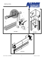
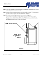
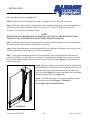
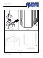
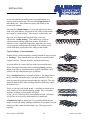
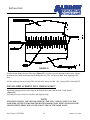
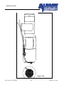
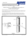
When the hinge pin is completely threaded through the entire length of the clips, loop it back through the
clips for six to eight inches, then back to the end again. Cut off excess on each end of the pin (Figure
37).
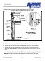
Install a width support between the side frames.
a. Measure the distance between the inside edge of rear windbar channel.
Cut a wooden board (i.e. 2x4) length to the distance measured in the previous step plus 3/8”.
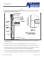
Wedge the board inside the rear C-channel at the same height that the clips are located on the top door
panel. The board will be used as a support when aligning the clips between the Full Vision Panel™ and
the top door panel. If necessary, secure the board to the side frames to prevent movement.
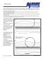
Using an approved lifting device (i.e. forklift), lift the bottom beam, bottom door panel, and attached Full
Vision Panel™ off the floor. The lifting device is being utilized to support the weight of the entire
bottom panel assembly while allowing the installer to the clips on both top and Full Vision Panel™.
Ensure the velcro strips are facing the front of the door panel.
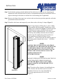
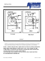
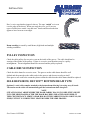
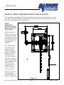
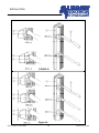
Clamp the Full Vision Panel™ to the board (in several places) to assist in supporting the weight and to
keep the clips aligned (Figure 38).
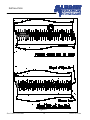
NOTE
WHILE SUPPORTING THE FULL VISION PANEL™ AND BOTTOM BEAM, IT IS
IMPERATIVE THAT THEY ARE KEPT AS SMOOTH AND STRAIGHT AS POSSIBLE.
WRINKLES IN THE JOINT BETWEEN THE FULL VISION PANEL™ AND BOTTOM DOOR
PANEL MAY WEAKEN THE LOWER HINGE PIN. WRINKLES IN THE DOOR PANEL
ITSELF MAY CAUSE CREASES TO DEVELOP WHICH CAN ULTIMATELY AFFECT THE
DOOR OPERATION.
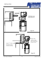
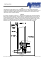
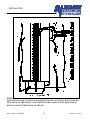
Thread the hinge pin through on clips both Full Vision Panel™ and top door panel (drawing #FVP0005).
Remove clamps and wooden board.
Re-apply tension to the bottom beam.
Reinstall bolts into intermediate pulley brackets (at center bolt hole position), and slowly release chain
pull tension on springs. If tension to the springs has been completely removed, then refer to the spring
installation and cable routing section.
Reattach velcro strips above and below Full Vision Panel™.
Close side frame covers and secure.
Re-apply power to control panel and actuate door several times to ensure a smooth operation.
Part Number 6410T0006
40
Release 10/15/2004