1
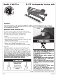
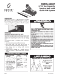
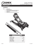
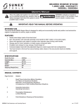
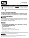
6613A
2 Ton Capacity Low Profile Jack with Quick Lift System
THIS OPERATING MANUAL CONTAINS IMPORTANT SAFETY INFORMATION.
READ CAREFULLY AND UNDERSTAND ALL INFORMATION BEFORE
OPERATING TOOL. SAVE THIS MANUAL FOR FUTURE USE.
OWNER/USER RESPONSIBILITY
INSPECTION
The owner and/or user must have a thorough understanding of
the manufacturer’s operating instructions and warnings before
using this jack. Personnel involved in the use and operation of
equipment shall be careful, competent, trained, and qualified
in the safe operation of the equipment and its proper use
when servicing motor vehicles and their components. Warning
information should be emphasized and understood.
Visual inspection should be made before each use of the service
jack, checking for leaking hydraulic fluid and damaged, loose or
missing parts. Each jack must be inspected by a manufacturer’s
repair facility immediately, if accidentally subjected to an
abnormal load or shock. Any jack which appears to be damaged
in any way, found to be badly worn, or operates abnormally
MUST BE REMOVED FROM SERVICE until necessary repairs
are made by a manufacturer’s authorized repair facility. It is
recommended that an annual inspection of the jack be made
by a manufacturer’s authorized repair facility and that any
defective parts, decals or warning labels be replaced with
manufacturer’s specified parts.
If the operator is not fluent in English, the manufacturer’s
instructions and warnings shall be read to and discussed with the
operator in the operator’s native language by the purchaser/owner,
making sure that the operator comprehends its contents.
Owner and/or user must study and maintain for future
reference the manufacturer’s instructions. Owner and/or user is
responsible for keeping all warning labels and instruction
manuals legible and intact. Replacement labels and literature
are available from the manufacturer.
A list of authorized repair facilities is available from the
manufacturer.
MAINTENANCE
IMPORTANT: When adding or replacing hydraulic fluid, always
use a quality hydraulic fluid. DO NOT use brake fluid, alcohol,
glycerine, detergent motor oil, or dirty oil as improper fluid can
cause serious internal damage to jack.
IMPORTANT! BEFORE USING THIS JACK:
1. Remove the threaded oil fill screw from the service jack.
2. Replace with threaded breather before use.
Oil fill screw to
be removed
Oil fill hole
To add hydraulic fluid: With saddle fully lowered and jack on
level ground, remove filler screw. Hydraulic fluid should be
filled to level of hydraulic fluid filler screw hole. If low, add
hydraulic fluid as needed.
Breather installed
Maintenance and Inspection: The owner and/or user must
maintain and inspect the jack in accordance with the
manufacturer’s instructions.
BEFORE USE
FOR YOUR SAFETY AND TO PREVENT INJURY:
Replace oil fill screw with breather as illustrated on page 1.
Air may become trapped in the hydraulic system during transit.
To purge air:
Use Service Jack for
lifting purposes ONLY.
1. Open release valve by turning handle counterclockwise.
2. Pump handle rapidly 4 full strokes. This will expel air that
may have entered hydraulic fluid passages during transit.
Always support
vehicle with
jack stands.
3. Close release valve by rotating handle clockwise and
pump handle.
4. If lift arm raised, jack is ready for use. If not, repeat
this procedure.
USE ONLY ON HARD LEVEL SURFACES.
LIFT ONLY ON AREAS OF THE VEHICLE AS SPECIFIED BY THE VEHICLE MANUFACTURER.
DO NOT GET UNDER A VEHICLE THAT IS ONLY SUPPORTED BY A TROLLEY/SERVICE
JACK–USE VEHICLE SUPPORT STANDS.
CENTER LOAD ON SADDLE PRIOR TO LIFTING. OFF-CENTER LOADS MAY CAUSE DAMAGE
TO JACK, LOSS OF LOAD, PROPERTY DAMAGE, PERSONAL OR FATAL INJURY.
THIS IS A LIFTING DEVICE ONLY. DO NOT MOVE OR DOLLY THE VEHICLE WHILE ON
THE JACK. IMMEDIATELY AFTER LIFTING SUPPORT THE VEHICLE WITH APPROPRIATE
MEANS.
NO ALTERATIONS TO THE JACK SHALL BE MADE.
DO NOT OVERLOAD. OVERLOADING CAN CAUSE DAMAGE TO OR FAILURE
OF THE JACK.
FAILURE TO HEED THESE WARNINGS MAY RESULT IN LOSS OF LOAD, DAMAGE TO JACK,
AND/OR FAILURE RESULTING IN PROPERTY DAMAGE, PERSONAL OR FATAL INJURY.
6613A — OPERATING MANUAL AND PARTS LIST
6613a_man071504en.indd 1
1
READ, STUDY AND UNDERSTAND THE OPERATING MANUAL PACKED WITH THIS JACK
BEFORE OPERATING.
rev. 07/15/04
7/15/04 5:15:35 PM
6613A
2 Ton Capacity Low Profile Jack with Quick Lift System
LUBRICATION
2.
All moving joints require lubrication often. Remove handle and
grease the lower end of handle where it rotates in the handle
socket. Using a grease gun, grease the lift arm pivot shaft grease
fitting until grease appears at the end of the shaft. Oil all lift
arm linkages, front wheels and rear casters.
To lower load: Open release valve VERY SLOWLY (by
turning handle counterclockwise). When release valve is
opened, saddle and load will be lowered. Lower the vehicle
slowly so as not to shock load the jack stands. Once repairs
are completed, raise vehicle enough to remove jack stands.
Lower vehicle very slowly.
OPERATING INSTRUCTIONS
CAUTION: Keep hands or feet away from the hinge mechanism
of the jack.
IMPORTANT: Before attempting to raise a vehicle, check vehicle
service manual for recommended lifting surfaces.
SPECIFICATIONS
1.
Capacity . . . . . . . . . . . . . . . . . . . . . . . . . . . . . . . . . . . . . . . . . 2 Ton
To raise load: Close release valve tightly (by turning handle
clockwise). DO NOT OVERTIGHTEN. Position jack under
load so that saddle will contact load firmly and load is
centered so it cannot slip. Operate jack handle until saddle
approaches the load. Once again check to see that saddle
is correctly positioned. Raise load to desired height. Place
jack stands of appropriate capacity under the vehicle. DO
NOT CRAWL UNDER VEHICLE WHILE LIFTING VEHICLE OR
PLACING OR REMOVING JACK STANDS! Place jack stands
at vehicle manufacturer’s recommended lift areas that
provide stable support for the raised vehicle.
Low Lift Height . . . . . . . . . . . . . . . . . . . . . . . . . . . . . . . . . . . . 2.9"
Raised Height . . . . . . . . . . . . . . . . . . . . . . . . . . . . . . . . . . . . 19.5"
Length . . . . . . . . . . . . . . . . . . . . . . . . . . . . . . . . . . . . . . . . . . . 28"
Weight . . . . . . . . . . . . . . . . . . . . . . . . . . . . . . . . . . . . . . . . 108 Lbs.
Chassis Width . . . . . . . . . . . . . . . . . . . . . . . . . . . . . . . . . . . . . 15"
Diameter Saddle . . . . . . . . . . . . . . . . . . . . . . . . . . . . . . . . . . 4.75"
LIMITED WARRANTY:
SUNEX INTERNATIONAL, INC. WARRANTS TO ITS CUSTOMERS THAT THE COMPANY’S SUNEX TOOLS® BRANDED
PRODUCTS ARE FREE FROM DEFECTS IN WORKMANSHIP AND MATERIALS.
Sunex International, Inc. will repair or replace its Sunex Tools® branded products which fail to give satisfactory service due
to defective workmanship or materials, based upon the terms and conditions of the following described warranty plans
attributed to that specific product.
This product carries a ONE-YEAR warranty. During this warranty period, Sunex Tools will repair or replace at our option any
part or unit which proves to be defective in material or workmanship.
Other important warranty information...
This warranty does not cover damage to equipment or tools arising from alteration, abuse, misuse, damage and does not
cover any repairs or replacement made by anyone other than Sunex Tools or its authorized warranty service centers.
The foregoing obligation is Sunex Tools’ sole liability under this or any implied warranty and under no circumstances shall we
be liable for any incidental or consequential damages.
Note: Some states do not allow the exclusion or limitation of incidental or consequential damages, so the above limitation or
exclusion may not apply to you.
Return equipment or parts to Sunex Tools, transportation prepaid. Be certain to include your name and address, evidence of
the purchase date, and description of the suspected defect.
If you have any questions about warranty service, please write to Sunex Tools. This warranty gives you specific legal rights and
you may also have other rights which vary from state to state.
Repair kits and replacement parts are available for many of Sunex Tools products regardless of whether or not the product is
still covered by a warranty plan.
MAILING ADDRESS:
Sunex Tools
P.O. Box 4215
Greenville, South Carolina 29608
SHIPPING ADDRESS:
Sunex Tools
315 Hawkins Rd.
Travelers Rest, South Carolina 29690
6613A — OPERATING MANUAL AND PARTS LIST
6613a_man071504en.indd 2
2
rev. 07/15/04
7/15/04 5:15:35 PM
6613A
2 Ton Capacity Low Profile Jack with Quick Lift System
Only those items listed with part
numbers are available as service
parts for this service jack.
Item
No.
Part
No.
1
2
3
4
5
6
7
8
9
10
11
12
13
14
15
16
17
18
19
20
21
RS3501
RS661303
RS661307
RS3511
RS320215
RS320216R
RS3526
RS3536
RS3534
RS661320
RS320221R
RS6613A21SK
Description
Retaining Ring
Washer
Wheel
Side Plate Assembly
Washer 12
Hex Nut M12
Caster Assembly
Hex Bolt M12 x 20
Spring Washer
Bolt
Spring Washer
Nut M16
Spring Washer 16
Screws
Torsion Spring
Handle Socket
Bolt
Handle Upper
Hex Bolt M6 x 35
Handle Lower
Power Unit Assembly
Seal Kit for Power Unit
6613A — OPERATING MANUAL AND PARTS LIST
6613a_man071504en.indd 3
Qty.
Item
No.
2
2
2
1
2
2
2
2
2
2
2
2
2
4
2
1
1
1
1
1
1
22
23
24
25
26
27
28
29
30
31
32
33
34
35
36
37
38
39
40
41
42
3
Part
No.
RS661332
RS35BR
RS3544
RS661344
Description
Spring
Inspection Plate
Hex Nut 24
Shaft Arm
Bolt
Retaining Ring 25
Long Linkage
Block Linkage
Retaining Ring 10
Saddle Block
Saddle
Linkage Axle
Washer 24
Breathing Screw
Pull Rod
Washer 8
Nut M8
Lift Arm Assembly
Handle Bumper
Split Pin 4 x 25
Release Assembly
Qty.
2
1
2
1
2
2
2
1
2
1
1
1
2
1
1
2
2
1
1
1
rev. 07/15/04
7/15/04 5:15:36 PM
6613A
2 Ton Capacity Low Profile Jack with Quick Lift System
TROUBLESHOOTING
SYMPTOM
POSSIBLE CAUSE
CORRECTIVE ACTION
Will not lift load
The release valve is not closed.
Turn the valve clockwise tightly.
Will not lift load
Will not lift full height
Low on hydraulic fluid.
Refill the jack to the correct level of hydraulic fluid.
Will not lift load
Pump seals and back-up
ring are defective.
Clean hydraulic fluid passages, replace seals and
renew hydraulic fluid.
(Must be serviced by qualified service center)
Will not lift full height
Will not lift smoothly or feels spongy
The hydraulic system is filled
with air.
Open the release valve, pump handle rapidly (4)
full strokes to purge air, close release valve.
Will not lower completely
Return spring is broken or
linkages binding.
Replace spring if broken. Grease pivot shaft,
oil all lift arm linkages.
Will not hold load or handle rises
Discharge ball is not sealing
hydraulic system and oil may
be dirty.
Manually flush hydraulic system by raising and
lowering lift arm by hand. Open the release valve,
as required to raise and lower the lift arm. Manually
raise and lower lift arm.
6613A — OPERATING MANUAL AND PARTS LIST
6613a_man071504en.indd 4
4
rev. 07/15/04
7/15/04 5:15:37 PM