1
Model # MFJ35A
3-1/2 Ton Capacity Service Jack
Description
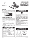
Model MFJ35A service jack is a self-contained device designed for lifting, but not sustaining, a partial vehicular load. It consists of a
frame with wheels and swivel casters supporting a mechanism that actuates a pivoting lift arm equipped with a saddle. It is designed
for use by professional auto mechanics.
Breather
IMPORTANT! BEFORE USING THIS JACK:
The breather located below hole in cross plate must be opened. Insert
slotted screw driver through hole and turn breather screw counter clockwise
until it stops turning. Do not force screw past stopping point.
Air may become trapped in the hydraulic system during transit.
To purge air:
1. Open release valve by turning handle counterclockwise.
2. Pump handle rapidly 4 full strokes. This will expel air that may have entered
hydraulic fluid passages during transit.
3. Close release valve by rotating handle clockwise and pump handle.
4. If lift arm raises to full height, jack is ready for use. If not,
repeat this procedure or follow trouble shooting instructions provided.
Inspection
Visual inspection should be made before each use of the jack, checking for
leaking hydraulic fluid and damaged, loose or missing parts. Each jack must
be inspected by a manufacturer’s repair facility immediately, if subjected to an
abnormal load or shock. Any jack which appears to be damaged in any way, is
found to be badly worn, or operates abnormally MUST BE REMOVED FROM
SERVICE until necessary repairs are made by a manufacturer’s authorized repair
facility. It is recommended that an annual inspection of the jack be made by a
manufacturer’s authorized repair facility and that any defective parts, decals or
warning labels be replaced with manufacturer’s specified parts. A list of
authorized repair facilities is available from the manufacturer.
FOR YOUR SAFETY AND
TO PREVENT INJURY:
Use Service Jack for
lifting purposes ONLY.
Always support vehicle with
jack stands.
THIS IS A LIFTING DEVICE ONLY. DO NOT MOVE OR DOLLY THE
VEHICLE WHILE ON THE JACK. IMMEDIATELY AFTER LIFTING
SUPPORT THE VEHICLE WITH APPROPRIATE MEANS.
DO NOT OVERLOAD. OVERLOADING CAN CAUSE DAMAGE TO OR
FAILURE OF THE JACK.
LIFT ONLY ON AREAS OF THE VEHICLE AS SPECIFIED BY THE
VEHICLE MANUFACTURER.
CENTER LOAD ON SADDLE PRIOR TO LIFTING. OFF-CENTER LOADS
MAY CAUSE DAMAGE TO JACK, LOSS OF LOAD, PROPERTY
DAMAGE, PERSONAL OR FATAL INJURY.
THIS JACK IS DESIGNED FOR USE ONLY ON HARD LEVEL SURFACES
CAPABLE OF SUSTAINING THE LOAD. USE ON OTHER THAN HARD
LEVEL SURFACES CAN RESULT IN JACK INSTABILITY AND POSSIBLE
LOSS OF LOAD.
NO ALTERATIONS TO THE JACK SHALL BE MADE.
READ, STUDY AND UNDERSTAND THE OPERATING MANUAL
PACKED WITH THIS JACK BEFORE OPERATING.
FAILURE TO HEED THESE WARNINGS MAY RESULT IN LOSS OF
LOAD, DAMAGE TO JACK, AND/OR FAILURE RESULTING IN
PROPERTY DAMAGE, PERSONAL OR FATAL INJURY.
Copyright © Professional Tool Products, 2005. All rights reserved.
MFJ35A
1
Rev. 08/09/05
3-1/2 Ton Capacity Service Jack
OPERATION
IMPORTANT: Before attempting to raise a vehicle, check vehicle service manual for recommended
lifting surfaces.
1. To raise load: Close release valve tightly (by turning handle clockwise).Position jack under load so that saddle will
contact load firmly and load is centered so it cannot slip. Operate jack handle until saddle approaches the
load. Once again check to see that saddle is correctly positioned. Raise load to desired height. Place jack stands
of appropriate capacity under the vehicle. DO NOT CRAWL UNDER VEHICLE WHILE LIFTING VEHICLE OR
PLACING OR REMOVING JACK STANDS! Place jack stands at vehicle manufacturer's recommended lift areas that
provide stable support for the raised vehicle.
2. To lower load: Open release valve VERY SLOWLY (by turning handle counterclockwise). When release valve
is opened, saddle and load will be lowered. Lower the vehicle slowly so as not to shock load the jack stands.
Once repairs are completed, raise vehicle enough to remove jack stands. Lower vehicle very slowly.
CAUTION: Keep hands or feet away from the hinge mechanism of the jack.
MAINTENANCE
IMPORTANT: When adding or replacing hydraulic fluid, always use a quality hydraulic fluid. DO NOT
use brake fluid, alcohol, glycerine, detergent motor oil, or dirty oil as improper fluid can cause serious internal
damage to jack.
To add hydraulic fluid: With saddle fully lowered and jack on level ground, remove breather.
The hydraulic fluid should just cover the surface of the internal cylinder visible through the hole.
Do not overfill. Replace breather. If low, add hydraulic fluid as needed.
Maintenance and Inspection: The owner and/or user must maintain and inspect the jack in
accordance with the manufacturer’s instructions.
LUBRICATION
All moving joints require lubrication on a regular maintance schedule. Remove handle and grease the lower end of
handle where it rotates in the handle socket. Using a grease gun, grease the lift arm pivot shaft grease fitting until
grease appears at the end of the shaft. Grease all lift arm linkages, front wheels and rear casters.
OWNER/USER RESPONSIBILITY
The owner and/or user must have an understanding of the manufacturer’s operating instructions and warnings
before using this jack. Personnel involved in the use and operation of equipment shall be
careful, competent, trained, and qualified in the safe operation of the equipment and its proper use when servicing
motor vehicles and their components. Warning information should be emphasized and
understood. If the operator is not fluent in English, the manufacturer’s instructions and warning shall be read to and
discussed with the operator in the operator’s native language by the purchaser/owner,
making sure that the operator comprehends its contents.
Owner and/or user must study and maintain for future reference the manufacturers’ instructions. Owner and/or
user is responsible for keeping all warning labels and instruction manuals legible and intact. Replacement labels
and literature are available from the manufacturer.
MFJ35A
2
Rev. 08/09/05
3-1/2 Ton Capacity Service Jack
Index
No.
Part
No.
1
2
3
4
5
6
7
8
9
10
11
12
13
14
15
16
17
18
19
20
21
22
RS3501
RS3502
RS35A05
RS35A06
RS3526
RS3511
RS3512
RS3516
RS3505-1
Description
Retaining Ring
Wheel
Side Plate Assembly
Bolt
Torsion Spring
Handle Socket
Bolt
Screws
Bolt
Spring Washer 18
Hex Nut M16
Caster Assembly
Hex Nut M16
Spring Washer 16
Spring Washer 12
Hex Bolt M12x20
Pull Rod
Hex Nut M12
Retaining Ring
Long Linkage
Retaining Ring 25
Shaft Arm
Index
No.
Qty.
23
24
25
2
2
1
2
1
1
1
4
2
2
2
2
2
4
4
2
1
2
2
2
2
1
Not
Shown
26
27
28
29
30
31
32
33
34
35
36
37
38
39
40
41
42
Part
No.
RS35A25
RS35A25SK
RS3501-1
RS3520A
RS3544
RS3535
RS3536
RS3534
RS35GF
RS3543
RS3506
RS3530
RS35BA
RS3524-1
RS3524-2
Description
Qty.
Spring Washer 24
Hex Nut M24
Power Unit Assembly
Complete Seal Kit for Power Unit
2
2
1
Spring
Washer
Block Linkage (incl.#29 &2 of #21)
Split Pin 4x25
Inspection Plate
Hand Bumper
Handle Lower
Handle Upper
Hex Bolt M6x35
Grease Fitting
Rubber Saddle Pad
Saddle
Lift Arm Assembly
Universal Joint Assembly
Breather
Pump Cover
Pin
2
2
1
1
1
1
1
1
1
1
1
1
1
1
1
2
2
Only items identified by part number are available for purchase.
MFJ35A
3
Rev. 08/09/05
3-1/2 Ton Capacity Service Jack
Warranty Notice...
Hydraulic Warranty Policy
Matco® shop equipment and tools, excluding accessories, are warranted against defects in materials or workmanship for a period of 1
year from original purchase. We will repair or replace at our option any defective part or unit which proves to be defective in material
or workmanship within this warranty plan. This warranty does not cover damage to equipment or tools arising from alteration, abuse or
misuse, and does not cover any repairs or replacement made by anyone other than Matco or its authorized service centers.
The foregoing obligation is Matco Tools sole liability under this or any implied warranty and under no circumstances shall we be liable for
any incidental or consequential damages.
NOTE: Some states do not allow the exclusion or limitation of incidental or consequential damages, so the above
limitation or exclusion may not apply to you.
Return equipment or parts to Matco Tools, or an authorized service center, transportation prepaid. Be certain to include your name and
address, evidence of the purchase date, and description of the suspected defect.
If you have any questions about warranty service, please write to Matco Tools, Stow, OH 44224. This warranty gives you specific legal
rights and you may also have other rights which vary from state to state.
PROPER STORAGE
It is recommended that the jack be stored in a dry location with all wheels touching the ground on
a relatively level surface.
TROUBLESHOOTING
Important: Service jacks are self-contained devices used for lifting, but not sustaining, a partial vehicular load. In accordance
with ASME-PALD standard, section 10-4.1.2 Load Sustaining Test: “A load not less than the rated capacity…shall not lower
more than 1/8” (3.18mm) in the first minute, nor a total of .1875” (4.76mm) in 10 minutes.” Leak down within this range
is considered normal operation and is NOT a warrantable defect.
ly
th
d
or
o
d
o
loa
ly
a
r
m
e
o
o
e
d
s
t
l iv
y
l
ho
low
lift
lift ong
lift cess
t
t
t
t
t
p
o
o
o
o x
es
no s
ll n ris
ll n ly
ll n ight
ll n n e
ll els
i
i
i
i
i
w le
w te
w e
w w
w fe
ck and
ck ple
ck ull h
ck s do
ck ack
a
a
a
a
a
J rh
J m
J f
J ak
J rj
o
co
its
le
o
EM
BL
O
R
P
SOLUTION
The release valve is not closed. Turn the valve clockwise tightly.
If this does not work, remove handle, lubricate handle
receptacle and handle end, then retry.
Low on hydraulic fluid. Refill the jack to the correct level of
hydraulic fluid.
Pump seals or back-up ring may be defective. Clean hydraulic fluid
passages, replace seals and refill hydraulic fluid.
(Must be serviced by qualified service center)
The hydraulic system has trapped air.
Open the release valve, pump handle rapidly (4) full strokes
to purge air, close release valve.
Return spring is broken or linkages are binding. Replace spring if broken. Grease pivot shaft and all lift arm linkages.
Discharge ball is not sealing hydraulic system and oil may be dirty.
Manually flush hydraulic system. Open the release valve, as required,
to raise and lower the lift arm. Manually raise
and lower lift arm.
MFJ35A
4
Rev. 08/09/05