1
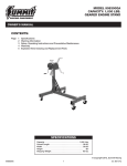
GEARED ENGINE STAND
1,000 LBS. CAPACITY
MODEL: 8300GA
Owner’s Manual
This is the safety alert symbol. It is used to alert
you to potential personal injury hazards. Obey all
safety messages that follow this symbol to avoid
possible injury or death.
WARNING
WARNING: Indicates a hazardous
situation which, if not avoided, could
result in death or serious injury.
IMPORTANT: READ THIS MANUAL BEFORE OPERATING
INTENDED USE
The Sunex Model 8300GA Engine Stand is designed to safely and conveniently handle and position most automotive
engines in preparation for service, repair or rebuild.
FEATURES
•
•
•
•
•
•
•
Sturdy base design made of structural steel.
63:1 ratio gearbox with manually operated crank handle for 360° rotation of mounted engine.
Worm drive gearbox locks engine in position when operator stops turning crank handle.
Storage area for tools, hardware or smaller engine component parts.
Foldable frame design for easy storage. Folded height 21".
Universal adapter head with fully adjustable fingers to match engine bolt hole configurations.
Two fixed wheels in front and two swivel locking caster wheels in the rear provide maximum stability
and support.
SPECIFICATIONS
Model Number:
Capacity (lbs.):
Length:
Width:
Height:
Shipping Weight (lbs.):
8300GA
1,000
34 1/4"
36 1/2"
36"
96
MANUAL CONTENTS
Page Number
1
2
3
4
Subject
Read These Instructions Before Operating
The Nature of Hazardous Situations
Methods to Avoid Hazardous Situations
Consequences of Not Avoiding Hazardous Situations
Assembly Instructions
Operating Instructions
Preventative Maintenance
Limited Warranty
Parts Breakdown Drawing and Nomenclature
8300GA: Parts Breakdown and Operating Manual
1
rev: 11/14/07
GEARED ENGINE STAND
1,000 LBS. CAPACITY
MODEL: 8300GA
Operating Instructions • Warning Information • Parts Breakdown
This is the safety alert symbol. It is used to alert
you to potential personal injury hazards. Obey all
safety messages that follow this symbol to avoid
possible injury or death.
WARNING
WARNING: Indicates a hazardous
situation which, if not avoided, could
result in death or serious injury.
IMPORTANT: READ THESE INSTRUCTIONS BEFORE OPERATING
BEFORE USING THIS DEVICE, READ THIS MANUAL COMPLETELY AND THOROUGHLY. UNDERSTAND ITS OPERATING
PROCEDURES, SAFETY WARNINGS AND MAINTENANCE REQUIREMENTS.
It is the responsibility of the owner to make sure all personnel read this manual prior to using the device. It is also the
responsibility of the device owner to keep this manual intact and in a convenient location for all to see and read. If the
manual or product labels are lost or not legible, contact Sunex Tools for a free replacement. If the operator is not fluent
in English, the product and safety instructions shall be read to and discussed with the operator in the operator’s native
language by the purchaser/owner or his designee, making sure that the operator comprehends its contents.
THE NATURE OF HAZARDOUS SITUATIONS
WARNING
The use of portable automotive lifting devices is subject to certain hazards that cannot be prevented by mechanical
means, but only by the exercise of intelligence, care, and common sense. It is therefore essential to have owners and
personnel involved in the use and operation of equipment who are careful, competent, trained, and qualified in the safe
operation of the equipment and its proper use. Examples of hazards are dropping, tipping or slipping of loads caused
primarily by improperly securing loads, overloading, off–centered loads, use on other than hard level surfaces, and using
equipment for a purpose for which it was not designed.
METHODS TO AVOID HAZARDOUS SITUATIONS
WARNING
•
•
•
•
•
•
•
•
•
•
•
•
•
•
Read, study and understand all instructions before operating.
Inspect the engine stand before each use. Do not use if damaged, altered, modified, in poor condition, or has loose
or missing hardware or components. Take corrective action before using the engine stand.
Do not use beyond rated capacity.
Use only on hard level surface capable of supporting the load.
Make sure all mounting hardware is securely tightened and setup is stable before rotating engine.
Always use high strength SAE grade 8 bolts for mounting engine to mounting head fingers.
Make sure widest set of mounting head fingers are nearest the ground when mounting engine to stand.
Assure the load is centered, balanced and secured to the mounting head and fingers. The engine’s weight should be
balanced within one inch of the mounting head’s rotational axis.
Never loosen mounting head bolts or engine mounting bolts unless engine is supported by a crane or hoist.
Only attachments and/or adapters supplied by Sunex Tools® shall be used.
Do not use stand or dolly to transport engine.
Do not crawl under engine or place any part of your body under engine at any time.
Refer to engine manufacturer’s service manual for proper lifting points, mounting points and bolt sizes. Mounting
bolts should be torqued at appropriate amount to maintain load.
Failure to heed these warnings and instructions may result in personal injury and/or property damage.
CONSEQUENCES OF NOT AVOIDING HAZARDOUS SITUATIONS
WARNING
Failure to read this manual completely and thoroughly, understand its OPERATING INSTRUCTIONS, SAFETY
WARNINGS, MAINTENANCE INSTRUCTIONS and not comply with them, and neglecting the METHODS TO AVOID
HAZARDOUS SITUATIONS could cause accidents resulting in serious or fatal personal injury and/or property damage.
8300GA: Parts Breakdown and Operating Manual
2
rev: 11/14/07
GEARED ENGINE STAND
1,000 LBS. CAPACITY
MODEL: 8300GA
ASSEMBLY INSTRUCTIONS
Assemble as shown in the diagram. 1 First, install the casters (5 & 16) to the front and rear axles (2 & 18) using the
hardware items 3, 4 & 6, being sure to insert bolts from the bottom side of caster plate. IMPORTANT: All hardware
that assembles items 2, 9, 18, 19 & 27 together should be assembled loose to ensure all bolts fit
through their designated holes. 2 Attach the center beam assembly (9) to the axle assemblies (2 & 18) using
hardware items 1, 10, 11 & 17. 3 Next, attach one end of brace (19) to the center beam using hardware items 1, 10,
and 11. Make sure position of brace is as shown in diagram. 4 PIace post (27) with gear box assembly onto base
assembly as follows: Stand the post on the base and attach by passing bolt, item 1, through middle hole in the base
bracket and the hex shaped mount welded to the bottom of the post. Then pass pin, item 7, through the upper hole
in the base bracket and just in front of the post. Secure pin with clip (8) provided. Now, insert pin, item 7, through the
rear hole, including both brackets and secure with clip (8) provided. 5 Attach the end of the brace, item 19, to the
post using pin and clip, items 7 & 8. 6 Now tighten all hardware that assembles items 2, 9, 18, 19 and 27 together. 7 Rotate the worm box (29) so its three holes line up with the holes in the post (27) and secure them with the hardware
25 and 26 provided. The worm box (29) should be positioned as shown in the diagram. 8 To fold engine stand,
simply remove the three pins and clips, fold brace forward, and then fold post forward. The pins and clips can be
stored in open holes.
OPERATING INSTRUCTIONS
This is the safety alert symbol used for the OPERATING INSTRUCTIONS section of this manual to alert you to
potential personal injury hazards. Obey all instructions to avoid possible injury or death.
NOTE: Do not mount engine to mounting plate unless all three pins, item 7, are in place and secured with number 8
clips provided according to the ASSEMBLY INSTRUCTIONS.
Consult the vehicle or engine manufacturer for service manuals and or technical bulletins that provide information
on suggested engine mounting tips, proper size and type mounting bolts and the engine’s center of balance. The
engine’s center of balance will have to be aligned with the rotational axis of the engine stand’s mounting head
assembly.
Drain oil and coolant and remove clutch bell housing and flywheel from engine before mounting. Attach an engine
lifting bar or sling to the engine and secure the bar or sling to a shop crane or hoist. Slowly lift the engine from its
compartment making sure no other vehicle components, wires or hoses obstruct the free movement of the engine.
Raise the engine high enough so its center of balance is close to the rotational axis of the stand’s mounting head.
Make sure, the four mounting head fingers are loosely connected to the mounting head plate. Secure the four
mounting head fingers to the bell housing end of the engine with the appropriate bolts and washers. Reposition
the mounting head, fingers and engine so the engine’s center of balance is within one inch of the mounting head’s
rotational axis. Tighten all bolts to a sufficient torque requirement that prevents any slippage.
Slowly lower the crane or hoist so the engine stand supports full weight of the engine. To check engine balance
and secure setup of the engine to the stand, slowly rotate the engine by turning the gear crank handle. If balance
or setup are not stable, rotate the engine to its original position, raise the crane or hoist so the weight of the engine
is removed from the stand and make the correct adjustments. After adjustments are made, tighten all bolts. This
adjustment procedure may have to be duplicated several times until correct. After the setup is balanced and secure,
the lifting bar or sling can be removed from crane or hoist.
To remove the engine from the stand, connect the lifting bar or sling to the crane or hoist and raise the engine high
enough to take the weight off the stand. Carefully remove the bolts that connect the four mounting fingers to the
engine. Be aware there will be a slight movement of stand as total engine weight is transferred to crane or hoist.
This engine stand has a folding feature that can save space or make storage easy. Just remove the three pins (7)
and their clips (8) so the brace (19) and post (27) can fit flat on top of the center beam assembly (9). The pins and
clips can be stored in the open holes.
8300GA: Parts Breakdown and Operating Manual
3
rev: 11/14/07
GEARED ENGINE STAND
1,000 LBS. CAPACITY
MODEL: 8300GA
PREVENTATIVE MAINTENANCE
This is the safety alert symbol used for the PREVENTATIVE MAINTENANCE section of this manual to alert you
to potential personal injury hazards. Obey all instructions to avoid possible injury or death.
1. Always store the engine stand in a well protected area where it will not be exposed to inclement weather,
corrosive vapors, abrasive dust, or any other harmful elements. The engine stand must be cleaned of water,
snow, sand or grit before using.
2. Lubricate the wheels, casters, zerk fittings, gear and rotating shaft with a general purpose grease.
3. Every engine stand owner is responsible for keeping the engine stand label clean and readable. Use a mild soap
solution to wash the external surfaces of the stand. Contact Sunex Tools for a replacement label if your stand’s
label is not readable.
4. Inspect the stand before each use. Do not use the stand if any component is cracked, broken or bent. Do not
use the stand if it has loose or missing hardware or components, or is modified in any way. Take corrective
action before using the stand again.
LIMITED WARRANTY...
SUNEX INTERNATIONAL, INC. WARRANTS TO ITS CUSTOMERS THAT THE COMPANY’S SUNEX TOOLS®
BRANDED PRODUCTS ARE FREE FROM DEFECTS IN WORKMANSHIP AND MATERIALS.
Sunex International, Inc. will repair or replace its Sunex Tools branded products which fail to give satisfactory
service due to defective workmanship or materials, based upon the terms and conditions of the following described
warranty plans attributed to that specific product.
This product carries a ONE-YEAR warranty. During this warranty period, Sunex Tools will repair or replace at our
option any part or unit which proves to be defective in material or workmanship.
Other important warranty information...
This warranty does not cover damage to equipment or tools arising from alteration, abuse, misuse, damage and
does not cover any repairs or replacement made by anyone other than Sunex Tools or its authorized warranty
service centers.
The foregoing obligation is Sunex Tools’ sole liability under this or any implied warranty and under no circumstances
shall we be liable for any incidental or consequential damages.
Note: Some states do not allow the exclusion or limitation of incidental or consequential damages, so the above
limitation or exclusion may not apply to you.
Return equipment or parts to Sunex Tools, or an authorized warranty service center, transportation prepaid. Be
certain to include your name and address, evidence of the purchase date, and description of the suspected defect.
If you have any questions about warranty service, please write to Sunex Tools. This warranty gives you specific legal
rights and you may also have other rights which vary from state to state.
Repair kits and replacement parts are available for many of Sunex Tools products regardless of whether or not the
product is still covered by a warranty plan.
Shipping Address: Sunex Tools • 315 Hawkins Rd. • Travelers Rest, SC 29690
Mailing Address: Sunex Tools • P.O. Box 4215 • Greenville, SC 29608
Telephone: (864) 834-8759
8300GA: Parts Breakdown and Operating Manual
4
rev: 11/14/07
GEARED ENGINE STAND
1,000 LBS. CAPACITY
MODEL: 8300GA
8300GA PARTS BREAKDOWN AND PARTS LIST
22
20
22
11
24
10
21
23
28
11
26 25
21
30
36
35
26
31
34
13
32
37
37
37
11
8
8
11
14
18
10
7
10
7
17
3
4
11
5
22
10
9
2
24
15
7
10
11
1
19
38
10
12
8
33
37
37
11
27
20
24
10
29
25
20
21
6
10
1
16
11
1
1
5
ITEM NO.
1
2
3
4
5
6
7
8
9
10
11
12
13
14
15
16
17
18
19
PART NO.
**
**
**
RS8300G16
**
**
**
**
**
*
*
*
*
RS8300G04
**
RS8300GA19
DESCRIPTION
Mounting Plate Bolt M12x70
Rear Axle Assembly
M8 Nyloc Nut
M8 Washer
3.5" Locking Swivel Caster
M8x20 Allen Head Bolt
Pin
Clip
Center Beam Assembly
M12 Washer
M12 Nut
Worm Crank
Grip
M5 Washer
M5x10 Bolt
3" Fixed Caster
M12x65 Bolt
Front Axle Assembly
Brace
QTY
4
1
16
16
2
16
3
3
1
10
10
1
1
1
1
2
2
1
1
* Available only in worm box assembly, part #RS8300GAWB
** Available only in bolt kit, part #RS8300GABK
8300GA: Parts Breakdown and Operating Manual
ITEM NO.
20
21
22
PART NO.
**
**
RS8300G26
23
RS8300GA23
24
25
26
27
28
29
30
31
32
33
34
35
36
37
38
**
**
**
RS8300GA27
*
*
*
*
*
*
*
*
*
*
DESCRIPTION
Mounting Plate Bolt M12x60
M12 Washer (4mm)
Finger
Mounting Plate - Shaft Assembly
12 Lock Washer
M8x25 Bolt
M8 Washer
Post
Grease Fitting
Worm Box
Worm Gear
Pin
Bearing Assembly
Worm
Worm Gear Pin
M25 Nut
Worm Box Cover (upper)
M4x6 Bolt
Worm Box Cover (lower)
QTY
4
4
4
1
4
3
3
1
2
1
1
1
2
1
1
1
1
7
1
Only items identified by part number are available separately.
5
rev: 11/14/07