1
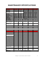
® SCHEMATICS ○ TEST PROCEDURES ○ MAINTENANCE SPECS GA - 2 0 0 9 - CD Manual No. GA2009CD CALIFORNIA Proposition 65 Warning: Engine exhaust and some of its constituents, and some dust created by power sanding, sawing, grinding, drilling and other construction activities contains chemicals known to the State of California to cause cancer, birth defects and other reproductive harm. Some examples of these chemicals are: Lead and lead-based paint. Crystalline silica from bricks. Cement and other masonry products. Arsenic and chromium from chemically treated lumber. Your risk from these exposures varies, depending on how often you do this type of work. To reduce your exposure to these chemicals: ALWAYS work in a well ventilated area, and work with approved safety equipment, such as dust mask that are specially designed to filter out microscopic particles. 2 Multiquip Inc. ◦ GA Series Generators ◦ Manual No. GA2009CD IMPORTANT! Read the operator's manual for safety instructions before you attempt to troubleshoot. Use extreme caution when troubleshooting power equipment. Never start or run power equipment inside a closed area, breathing exhaust fumes can kill. Basically, a tool is an object that enables you to take advantage of the laws of physics and mechanics in such a way that you can seriously injure yourself. This service manual is intended to provide information and procedures to safely maintain, repair and give a basic understanding of service techniques for the GA series generators. You must be familiar with the operations of the GA series generator before attempting to troubleshoot or make repairs. Basic operating and maintenance procedures are described in the operation and parts manual supplied with the generator. Use the supplied manual to order replacement parts. If you are missing the operation and parts manual, please contact Multiquip Inc to order a replacement or you may visit our website at www.multiquip.com For your safety and the safety of others carefully read, understand and observe all instruction described in this manual. THE INFORMATION CONTAINED IN THIS MANUAL IS BASED ON GA-SERIES GENERATORS MANUFACTURED UP TO THE TIME OF PUBLICATION. MULTIQUIP INC. RESERVES THE RIGHT TO CHANGE ANY PORTION OF THIS INFORMATION WITHOUT NOTICE. Multiquip Inc. ◦ GA Series Generators ◦ Manual No. GA2009CD 3 CONTENTS Maintenance Specifications…………………………………….…………………5 Inspection…………………………………………………………………………6-8 How AC Voltage is Produced……………………………………………………..9 TROUBLESHOOTING Troubleshooting………………………………….………………………….…10-11 TEST PROCEDURES Excitation………………………………………….……………………………….12 Diode Rectifier………………………………………………..…………….……..13 Stator……………………………..……………………………………………….. 14 Rotor………………………………………………………………………………..15 GENERATOR TIPS Current Flow Diagram…………………………………………………………….16 Rotor Removal Tips………………………..………………………………….…..17 GFCI...………………....………………………….…………………………….….18 Flashing the Field………………………………………………………………….19 Circuit Breakers / Short Circuits………………………………………………….20 Meg-Ohm-Meter……………………………………………………………………21 ENGINES Index…..………………………………………………….…………..…………22-37 WIRING SCHEMATICS GA-2.5H………………………………………………………………….….…38-39 GA-2.9R…………………………..……………………………..………….…......40 GA-3.6HA ……………………………………………………………..……... ….41 GA-4.5RA … ………………………………………………………………...…..42 GA-6HA ….. ……………………………………………………………..……..43 GA-6HEA…………………………………………………………………..…… . 44 GA-6REA………………………………………………………………..…… . …45 GA-9.7HE………………………………………………………………..….......…46 4 Multiquip Inc. ◦ GA Series Generators ◦ Manual No. GA2009CD MAINTENANCE SPECIFICATIONS GA2.5H GA2.9R GA3.6HA GA4.5RA GA6HA Engine Model Honda GX160 Robin EX170 Honda GX240 Robin EX270D Honda GX340 Horse Power 5.5 5.7 Engine (RPM) Hi-speed rated under load Fuel Type High 3600 High 3600 8 9 11 High 3600 High 3600 High 3600 Low 2500 Low 2500 Low 2500 Gasoline Gasoline Gasoline Gasoline Gasoline Fuel Capacity 3.2 gal. 3.6 gal. 5 gal. 5 gal. 5 gal. Fuel filter (inside tank) 300 hrs, 100 hrs. 300 hrs. 100 hrs. 300 hrs. NGK BPR6ES NGK BR6HS NGK BPR6ES NGK BR6HS NGKB6HS .028"-.031" .024"-.027" .028"-.031" .024"-.027" .028"-.031" 1.1 qt. 1.1 qt. Sparkplug Sparkplug Gap Eng. Oil Type Eng. Oil Capacity Eng. Oil Service Engine Compression Valve Clearance (Cold) Air Filters SAE 10W30 .6 qt. 1.1 qt. 1.1 qt. 100 hrs. 85-121PSI 85-121 PSI 85-121 PSI 85-121 PSI 82-102 PSI Intake: .006" Exhaust: .008" Intake: .003" Exhaust: .005" Intake: .006" Exhaust: .008" Intake: .003" Exhaust: .005" Intake: .006" Exhaust: .008" 50 hrs. 100 hrs. 50 hrs. 100 hrs. 50 hrs. Generator End Brushless ( No maintenance required ) Always review and follow detailed maintenance & service instructions as provided in the equipment manual GA6HEA GA6REA GA9.7HE Engine Model Honda GX340 Robin EH36 Honda GX610 Horse Power 11 11 10.7 High 3600 High 3600 High 3600 Low 2500 Low 2500 Low 2500 Gasoline Gasoline Gasoline 5 gal. 5 gal. 10 gal. Engine (RPM) Hi-speed rated under load Fuel Type Fuel Capacity Fuel filter (inside tank) 300 hrs, 100 hrs. 300 hrs. Sparkplug NGK B6HS NGK B6HS NGK BPR6ES Sparkplug Gap .028"-.031" .028"-.031" .028"-.031" Eng. Oil Type SAE 10W30 SAE 10W30 SAE 10W30 Eng. Oil Capacity Eng. Oil Service 1.1 ltr. 100 hrs. oil .8 ltr. 100 hrs. 1.5 ltr. 100 hrs. Coolant capacity Engine Compression N/A 82-102 PSI N/A 85-121 PSI N/A 85-114 PSI Intake: .006" Exhaust: .008" Intake: .003" Exhaust: .004" Intake: .006" Exhaust: .008" 50 hrs. 100 hrs. 50 hrs. Interstate Interstate Interstate 12N24-3A 12N24-3A SP30 Valve Clearance (Cold) Air Filters Battery Generator End Brushless ( No maintenance required ) Multiquip Inc. ◦ GA Series Generators ◦ Manual No. GA2009CD 5 GENERATOR INSPECTION Before you try to diagnose a generator problem, check the engine to make sure that it has been serviced and is operating correctly. Perform proper maintenance and tune-up procedures before evaluating the generator. Check the engine governor to ensure the engine remains at a stable rpm when electrical loads are applied. The generator engine's governed rpm isn't as critical for power tools and resistance loads, such as electric wire heaters, as it is for machines tuned to 60 cycles per second (cps) current. For example, if an engine must run at 3,600 rpm, it must have a 60-cps current to time it. If the current is 61 cps, the engine would run at 3,660 (61 cycles x 60 seconds) rpm. Having a volt-ohm meter (VOM) that accurately measures alternating current is a must when servicing generators. The first step in generator troubleshooting is to conduct a visual inspection before doing any electrical tests. Looking the generator over carefully should expose any environmental factors that might contribute to the problem. As you remove the generator control box cover and begin your inspection, look for the following: 1. Rusted or corroded connections. An oxidized connection will prevent the circuit from being completed. This applies not only to the major cables externally, but also to the electronic control devices internally. 6 Multiquip Inc. ◦ GA Series Generators ◦ Manual No. GA2009CD GENERATOR INSPECTION - continued - 2. Carbon flash deposits around the 120V AC and 240V AC receptacles. This will indicate whether the device that was plugged into the generator shorted out the receptacle. The device may have shorted the generator to ground and caused a carbon flash when the plug prongs touched the receptacle. 3. Signs of overheating. Discoloration and a burnt smell should be noticeable inside the generator. Look to see if the windings turned black. The insulative sprays that manufacturers use to insulate the windings may vary in color from shades of reddish brown to light brown to dark brown, so try to compare the color to that of a new unit. 4. Wire insulation that is heat-hardened. Fabric and plastic insulation hardens over time due to heat exposure and overheating. Long-term heating should be more uniform. A short, excessive heat cycle may have less hardening and burning at the unit's outer perimeters and excessive heat signs toward the center or heat source. 5. Insects that have developed a community inside the generator. Their nests and debris can cause electrical shorts. Generators left out in the elements, such as for running water wells, provide a nice home for critters such as spiders, wasps, and mice. 6. Loose bolts, screws, and fasteners. This condition will either prevent full-time service or give intermittent service depending on the situation. 7. Problems in quick disconnect connectors. These are often overlooked. A quick disconnect could have one to a dozen male-female connections. These are often inside some plastic or rubber cover that prevents you from seeing any possible corrosion. In electrical troubleshooting, always unplug and plug in all connectors three times to produce a freshly scraped metallic surface for good electrical contact. If the unit works after that, soak the connectors first in vinegar for a few minutes, then in a baking soda solution. Rinse the unit thoroughly, with distilled water. This acid/base wash will remove corrosion, but not oil or grease. Blow dry thoroughly. If you know how to use an ohm meter, check for zero ohms on all connections. Spray the contacts with an electrical insulative spray before reassembling them. Multiquip Inc. ◦ GA Series Generators ◦ Manual No. GA2009CD 7 GENERATOR INSPECTION - continued - 8. Crimp connections. These connections have several problems. Even though they're widely used, they represent the least professional fix. First, they come loose as the machine vibrates, and lose consistent, quality contact. Second, because dissimilar metals are in contact, a galvanic cell is set up that result in corrosion when moisture is present. 9. Solder joints that have cracked or broken loose. This condition occurs much less frequently than crimped connections and basically results from poor-quality workmanship. 10. Worn insulation allowing wires to short. Insulation deteriorates from physical contact when wires rub together due to vibrations. Eventually, the internal wires can short to each other or to ground. 11. Crossed wires. Mistakes happen, especially if someone else worked on the generator before you. 12. Fuses, circuit breakers, and ground fault interrupts. These can easily be tested with a volt-ohm-meter. After conducting a thorough physical inspection of the generator, replace the cover, and start the engine. Take voltage readings on all the receptacles. What are they? Does a 120V AC receptacle read 128V AC? Is this bad? Normally, it isn't. Lower voltages are more detrimental than higher voltages. Lower voltages overload electric motors very easily and cause them to burn. How high should a voltage go? No more than 130 volts for some appliances and less for others. Keep the output voltage approximately 120 to 125V AC. Electricity providers deliver 128V AC to residential homes. Resistance measurements can be taken and compared to specifications. With the generator isolated from any alternating current source, a volt-ohm meter often pins down the problem without having to take voltage readings internally while the unit is running. 8 Multiquip Inc. ◦ GA Series Generators ◦ Manual No. GA2009CD HOW IS (AC VOLTAGE) PRODUCED? 1) Engine (see engine manual) The engine running at 3600 rpm (60Hz) creates excitation voltage. 2) Excitation (see page 12) AC Voltage is produced from magnets which are located on the flywheel of the engine. As the magnets pass a set of windings (charge coils) beneath the flywheel they produce alternating current, (AC). 3) Diode Rectifier AC/DC (see page 13) A full wave diode rectifier converts the AC voltage to DC voltage. 4) Stator (see page 14) The DC voltage is sent from the full wave diode rectifier via wires J & K to excitation winding, which are located in the stator. This produces a magnetic field in the stator. 5) Rotor creates AC and is converted to DC (see page 15) Excitation windings on the rotor pass through the magnetic field of the stator creating AC voltage. AC voltage in the rotor is then converted to DC voltage by use of full wave diode rectifiers mounted on the rotor, producing a rotating magnet. 6) AC is produced The rotating magnetic field passes through the main windings located in the stator (U1, V1, U2, and V2). These windings provide AC voltage to the receptacles through a circuit breaker. Multiquip Inc. ◦ GA Series Generators ◦ Manual No. GA2009CD 9 TROUBLESHOOTING The following is a few basic scenarios. If you don’t see your situation here, try checking the Technical Information bulletins on our website at www.multiquip.com or contact one of our Technical Support coordinators at (800) 421-1244 SYMPTOM Low voltage. Low or no voltage, engine RPM is good. Engine does not accelerate from low to high speed. Engine does not idle down all the way POSSIBLE PROBLEM SOLUTION Engine speed to low Adjust to specification Defective excitation lamp coil Check coil see pg.12 Loose wire connection Check all wire connections and control box wiring. Defective diode rectifier Check diode rectifier see pg.13 Leakage breaker malfunction Check circuit breaker. GFCI circuit breaker is open Reset GFCI circuit breaker Stuck idle control solenoid Check or replace solenoid Defective Idle control switch Check or replace switch Defective diode rectifier Check diode rectifier see pg.13 Defective slowdown unit Check slowdown unit see pg.27 High speed out of adjustment Adjust to specification Governor out of adjustment Check governor is adjusted correctly and linkage is not obstructed. Carburetor out of adjustment Check carburetor is adjusted correctly and tension spring is not obstructed Check solenoid is in correct position and working properly Idle control solenoid Check power connection from lamp coil and rectifier 10 Multiquip Inc. ◦ GA Series Generators ◦ Manual No. GA2009CD TROUBLESHOOTING For more on engines see engine manufactures manual or you may contact one of our Technical Support coordinators at (800) 421-1244 SYMPTOM POSSIBLE PROBLEM Fuel valve is in the “Off” position or partially closed Turn fuel valve to the “On” position Engine switch is in the “Off” position Set switch to the “On” position Low oil level Fill crankcase to proper oil level or place generator on level surface. Fuel delivery system Check fuel filter and ensure fuel flow to carburetor is sufficient. Also check fuel tank for contaminated or stale fuel, replace if necessary. Flooded Wait 5 minutes and re-crank engine Carburetor inadequate air supply Check or replace clogged air filter Intake valve stuck open or closed Inspect valves and valve clearance No spark Check condition of spark plug and ignition coil. Inspect wires to the on / off switch. Defective anti-backfire solenoid Check solenoid see pg.24 Engine speed is to low Raise engine speed to rated RPM Generator is overloaded Check connected device amperage is application sufficient Short circuit in a connected load Disconnect shorted electrical device Generator will not start: or starts and runs rough Engine backfires Engine runs good at noload but “bogs down” when loads are applied. SOLUTION Check or replace clogged air filter Carburetor inadequate Ensure carburetor jets are not clogged Multiquip Inc. ◦ GA Series Generators ◦ Manual No. GA2009CD 11 EXCITATION LAMP COIL How to check the coil AC voltage is produced from charge coils and permanent magnets which are located on the flywheel of the engine. Check voltage output with engine running. Disconnect the charge coil leads by removing a black plastic protector sheath at the engine wiring harness Lamp coil . Example engine shown, Honda GX series One set of charge coil wires is for excitation. One set is for the idle control slowdown. Lamp Coil (AC) (Nominal readings +/- 10% engine speed 3600 RPM, no load) Output Wires Voltage AC Green to White - - - - - - - - - - - -- - - - - - - - - - - 22 Volts Green/White to Green/White - - - - - - - - - - - - 23 Volts Green/White to Green/White - - - - - - - - - - - - 23 Volts 12 Multiquip Inc. ◦ GA Series Generators ◦ Manual No. GA2009CD Engine (Honda GX-Series) (Robin EH-Series) (Robin EX-Series) DIODE RECTIFIER AC/DC How to test the Diode Rectifier There are two ways to check the diode rectifier. The Diode Rectifier supplies DC voltage to the stator. To check Diode voltage output, disconnect the J & K wires at the harness that are connected to the stator with yellow wires. The two yellow wires will be connected with quick disconnect connectors. Diode Rectifier Output (DC) (Nominal readings +/- 10% engine speed 3600 RPM, no load) Output Wires Voltage DC Yellow to Yellow - - - - - - - - - - - - - - - - - - - - - - 12 - 18V DC Model (ALL) Yellow Wires Diode Rectifier Continuity To properly check continuity you must disconnect (un-solder) or isolate the leads connected to the Diode. Check for continuity / no continuity as shown below. Multiquip Inc. ◦ GA Series Generators ◦ Manual No. GA2009CD 13 STATOR How to check the Stator The GA series stators have output wires that lead from the inner stator windings, which provide 120V AC output and lead to a circuit breaker then to the receptacles and two excitation wires labeled J & K that receive 12V DC from the diode rectifier. Some stators will have (2) extra wires for battery charging purpose. Stator Windings Voltage AC (Nominal readings +/- 10% engine speed 3600 RPM, no load) Output Windings Voltage AC U1 to V1 & U2 to V2 - - - - - - - - - - - - - - - - - - - - 120V AC >>> Model (ALL) NOTE: Winding resistance specifications taken @ 20º C / 68º F <<< Ω Resistance (Nominal readings +/- 10% engine off) Output Windings Resistance U to V - - - - - - - - - - - - - - - - - - - - - - - - - - - - - - - U1 to V1 - - - - - - - - - - - - - - - - - - - - - - - - - - - - - U1 to V1 - - - - - - - - - - - - - - - - - - - - - - - - - - - - - - U to V - - - - - - - - - - - - - - - - - - - - - - - - - - - - - - - Excitation Windings .6 Ω .25 Ω .16 Ω .4 Ω (GA-2.5), (GA-2.9) (GA-3.6), (GA-4.5) (GA-6) (GA-9.7) Resistance J to K - - - - - - - - - - - - - - - - - - - - - - - - - - - - - - - - 1.46 Ω 1.63 Ω 1.8 Ω Battery Charging Windings Model Model (GA-2.5), (GA-2.9) (GA-3.6), (GA-4.5), (GA-6) (GA-9.7) Resistance A to B - - - - - - - - - - - - - - - - - - - - - - - - - - - - - - - - - .1 Ω 14 Multiquip Inc. ◦ GA Series Generators ◦ Manual No. GA2009CD Model (GA-6), (GA-9.7) ROTOR The rotor can not be tested Perform all other test to eliminate all other possible problems before replacing the rotor. This brushless designed rotor has integrated diode rectifiers. When the rotor rotates in the stator, AC voltage is generated in the rotor windings. The AC voltage is sent to the diode rectifiers (located on the rotor) and is converted to DC voltage producing a rotating magnet. While the rotating magnet field passes through the main windings located in the stator, this produces AC Voltage – 120V AC. GA – Series Rotor Multiquip Inc. ◦ GA Series Generators ◦ Manual No. GA2009CD 15 CURRENT FLOW DIAGRAM Excitation Charge Coil Creates AC Diode Rectifier Converts AC to DC Rotor Stator Circuit Breaker NOTE: Current flow diagram represents the basic flow in the generator and does not include controls example: Idle control switch and slowdown module (RC) (see pg. 27) 120 / 240 power switch (see operation and parts manual for specific model) Receptacle 16 Multiquip Inc. ◦ GA Series Generators ◦ Manual No. GA2009CD ROTOR REMOVAL TIP Remove and modify existing rotor bolt (fig 1). Measure back ¾” and cut bolt head off. Make a shallow groove on shaft, this will allow you to thread the rotor bolt into the engine shaft using a flat head screw driver (fig 2). NOTE: a replacement bolt will be required for re-assembly. Save this modified bolt as a tool for future repairs. Install a 12mm – 1.5 hex head bolt into the end of the rotor assembly shaft (fig 3). Torque the down until the rotor separates from the engine shaft. Multiquip Inc. ◦ GA Series Generators ◦ Manual No. GA2009CD 17 GFCI What is a Ground Fault Circuit Interrupter? A ground fault circuit interrupter (GFCI) is a small device that compares the amount of electricity flowing to and from the tool used on the generator. If there is a difference of more then 5 milliamps (.005 amps) the GFCI opens the circuit. What are the limits of a GFCI? There are several limitations that you should be aware of 1. A GFCI is not a tool tester. The GFCI does not have the sensitivity, detection circuits, nor the polarity, reversal features needed to perform the function of a tool tester. The GFCI makes an excellent life protection device, but a very poor tool tester. 2. A GFCI does not prevent shocks. The GFCI is only operated when a ground fault occurs. Someone using the equipment might receive a shock, but it will be a very short duration (1/30 of a second). There is a chance that a shock, even of this short duration, might cause someone to experience a fall or similar injury, but electrocution will normally be prevented. 3. A GFCI does not prevent all electrocutions. The GFCI reacts to electric current flowing from the power line to ground. It does not react to current flow between power lines. In other words, the GFCI will react to someone standing in water and comes in contact with one of the power lines. It will not protect someone who is hold the neutral power line in one hand and hot wire with the other. 4. A GFCI does not replace fuses or circuit breakers. Fuses and circuit breakers are designed to protect equipment and power lines by reacting to excessive current flow, normally in the order of 15 to 20 amps. 5. GFCI’s are designed to protect people by reacting to leakage currents to ground in the order of .005 amps. Except in the case of GFCI / circuit breaker combinations sold to be installed in building installations, they are separate devices performing separate functions. Is the ground wire still needed? The GFCI will work and perform its function with or without the tool being grounded, but the ground system is an important safety feature and should always be maintained and retested on a regular basis. Further, if a ground fault should occur, the leakage current will pass down the ground wire and trip the GFCI without the operator receiving a shock at all. So YES – please retain the ground system. How can we be sure the GFCI is working? There are two methods of testing GFCI’s. All GFCI’s sold in this country are provided with a test and reset button. During maintenance intervals simply plug a tool in to the GFCI and press the test button. The tool should turn-off and the reset button should pop-out. Depressing the reset button should restart the equipment. This is an adequate test for most applications. To measure the actual trip current of a GFCI requires a GFCI tester. The tester allows you to read the actual GFCI trip current on a meter, identifying the GFCI’s that do not operate within the required four to six milliamp range. One test that should not be performed on GFCI’s is a high load test. The GFCI contains small electronic parts that are damaged if high voltages are applied to them. DO NOT test any GFCI on a HI-POT, dialectic, or Doyle type tester. 18 Multiquip Inc. ◦ GA Series Generators ◦ Manual No. GA2009CD FLASHING THE FIELD Generator Field Flashing The GA series generator DOES NOT require flashing the field as it is equipped with a self excitation lamp coil. The lamp coil behind the engine flywheel produces AC voltage that is then converted to DC voltage by a rectifier in the control panel. This DC voltage is used to assist the stator in creating the needed magnetic field to complete the generator process. Generators that require flashing the field: this condition is usually caused by insufficient residual magnetism in the exciter and generator fields. In some cases a generator that has been out-of-service for an extended period may lose its residual magnetism and require flashing. Residual magnetism is restored by flashing the field thereby causing a current surge in the generator. This type of generator relies on the residual magnetism stored in the armature to produce the needed voltage to create the magnetic field to complete the generator process. When residual magnetism is not present, this is known as generators that will, “lose their magnetism” or “go flat”. The GA series generator does not rely on stored residual magnetism to create a magnetic field thus eliminating the need to flash the field. If the GA series generator has low or no AC voltage output it is not due to loss of residual magnetism. See the troubleshooting section in this service manual for “low or no voltage”. Multiquip Inc. ◦ GA Series Generators ◦ Manual No. GA2009CD 19 CIRCUIT BREAKERS A circuit breaker is an automatically-operated electrical switch designed to protect an electrical circuit from damage caused by overload or short circuit. Its basic function is to detect a fault condition and, by interrupting continuity, to immediately discontinue electrical flow. Unlike a fuse, which operates once and then has to be replaced, a circuit breaker can be reset (either manually or automatically) to resume normal operation. NOTE: always place the main circuit breaker in the “OFF” position prior to starting the engine. SHORT CIRCUITS A short circuit (sometimes abbreviated to short or s/c) in an electrical circuit is one that allows a current to travel along a different path from the one originally intended. The electrical opposite of a short circuit is an "open circuit", which is an infinite resistance between two nodes. It is common to misuse "short circuit" to describe any electrical malfunction, regardless of the actual problem. Damage from short circuits can be reduced or prevented by employing fuses, circuit breakers, or other overload protection, which disconnect the power in reaction to excessive current. Dude, why such long wires? Don’t want any short circuits 20 Multiquip Inc. ◦ GA Series Generators ◦ Manual No. GA2009CD MEG-OHM-METER Good Insulation Every generator winding, motor and extension cord have electric wire that is covered with some form of insulation. Electrical wire is normally copper and it is a good conductor of the electric current that powers motors. The wires insulation must be the opposite of a conductor; it should resist the current and keep it in its path along the conductor. The purpose of the insulation around a conductor is similar to that of pipe carrying water. Pressure on water from a pump causes flow along the pipe. If the pipe was to spring a leak you’d waste water and lose some water pressure. With electricity, voltage is like the pump pressure causing current to move along the copper wire. As with the flow of water in a pipe, there is resistance to flow of current but it is much less along the conductor than through its insulation. It should be noted that no insulation is perfect; meaning has infinite resistance, so some electricity does flow along the insulation or even through it to ground. The current passing through the insulation may only be a millionth of an ampere (one microampere) but it is the basis of insulation testing. A higher voltage tends to cause more current leakage through the insulation. This current leakage would become a problem if the insulation has deteriorated. All this leads us to determine “what is good insulation”. Under normal conditions “good” means a relatively high resistance to current. Or it can also be stated that a good insulation has the ability to keep a high resistance. A suitable way of measuring resistance can tell us how good the insulation is. Also if regular insulation measurements are made you can track trends towards its deterioration. Causes of Bad Insulation When generators, welders and electric motors are new the insulation should be at its highest level of resistance. During equipment use, insulation is subject to many effects which can cause it to fail. These causes can be mechanical damage, vibrations, excessive heat or cold, dirt, oil, corrosive vapors and even moisture from humidity. During the life of a conductor’s insulation all of these causes are at work in combination with electrical stresses. If a pin hole or even a crack in the insulation develops, moisture and foreign matter can penetrate the surfaces of the insulation. This provides for a low resistance path for leakage current. Once the insulation has begun to deteriorate all elements of causes tend to combine until excessive current leakage is allowed through the insulation. At times the drop in insulation resistance can be sudden, such as occurs if the equipment is flooded. Normally insulation resistance drops gradually and gives plenty of warning if checked as a preventative maintenance. Periodic checks would allow planned reconditioning prior to operation failure and the ability to remove from service if the insulation resistance became dangerously low. Equipment with no checks may not only be dangerous to touch with voltage applied but also be subject to total burn out. A failed insulator becomes a partial conductor. For more information on Meg-Ohm-Meters visit our website at www.multiquip.com look at Technical Information bulletins under Meg-Ohm-Meters. Multiquip Inc. ◦ GA Series Generators ◦ Manual No. GA2009CD 21 ENGINES The GA-Series generators are powered by four cycle engines and are manufactured by Honda and Robin. The next few pages are tips and instructions on basic maintenance for the engines used on the GA-Series generators. The following information is to provide the service technician with a base level of knowledge on engine maintenance. For more on engine repairs see engine manufacturer’s service manual. INDEX Engine Part Details Carburetors ………………………………………………………………………………….…23 Anti-Back-Fire Solenoid ………………………………………………………………….…...24 Spark Plugs ………………………………………………………………………………...25-26 Slowdown Module (RC) ……………………………………………………………….………27 Engine Maintenance Engine Maintenance……………………………………………………………………….......28 Oil Leaks ………………………………………………………………………………………29 My Engine Won’t Start………………………………………………………………………....30 Stale Fuel………………………………………………………………………………………..31 HONDA Carburetor ..……………………………………………………………………………………32 Ignition Coil...……………………………………………………………………………...……33 Oil Level Switch .……………………………………………………………………………….34 ROBIN Ignition Coil……………………………………………………………………………………..35 Oil Level Switch………………………………………………………………………………..36 Engine Manufacturer’s Contact Information Contact Information.…………………………………………………………………………..37 22 Multiquip Inc. ◦ GA Series Generators ◦ Manual No. GA2009CD CARBURETORS Idle mixture screw Idle speed screw Choke plate Throttle plate Fuel / air mixture flows to engine. Fuel filter Float Float bowl Jet Pedestal Carburetor and fuel problems can fall into several categories and it is important to determine what is happening before proceeding with a rebuilt on the carburetor. If the carburetor is leaking fuel especially while setting or just not getting fuel, you may have a contaminated fuel problem. You should look first at the fuel in your tank for any signs of dirt, water, rust or varnish build up. Before you consider rebuilding or replacing the carburetor you must have good clean fuel flow to it. When possible install the proper fuel filter for your application. Non-fuel pump engines use a different filter then fuel pump engines in most cases. It does no good to clean a carburetor and put contaminated or old fuel back into it. In some cases a rusty or badly varnished fuel tank will need to be replaced. Here's a list of things to think about when evaluating whether to rebuild your carburetor: Does the engine run well under load, does it idle ok, does the governor hunt? Is the carburetor in usable condition, throttle shafts, linkages loose? After removing the bowl, do you have water corrosion, varnish or dirt? Is there any sign of warpage on the mounting surfaces? Is the float and bowl ok, are they pitted and possibly leaking? Is the carburetor leaking fuel while just setting, possibly into the crankcase? After evaluating the questions above, you will be able to make a more informed decision on whether to rebuild or replace your carburetor. Clean up is important, especially if you have a varnish problem. If you have a water corrosion problem, which looks like a white powder rust, you may want to just replace the carburetor. Carburetor cleaner will not clean water corrosion. Do not take the carburetor totally apart until you have the repair kit. You do need to determine if you need a new float, bowl or other parts not included in the repair kit. Most repair kits include a needle valve and all gaskets. Multiquip Inc. ◦ GA Series Generators ◦ Manual No. GA2009CD 23 ANTI BACK-FIRE SOLENOID The anti-back-fire solenoid is sometimes confused with a fuel shutdown solenoid. A fuel shutdown solenoid on a diesel engine stops the fuel supply to the engine and is the main component to shut the engine down. On a gasoline engine, the engine is shutdown by grounding the ignition coils secondary winding. During engine run down, as the piston travels downward in the cylinder; vacuum is still being created in the carburetor. This vacuum continues to drawn raw fuel into the engine and to the hot muffler. Since the fuel does not combust in a controlled burn without the spark ignition, the fuel can then ignite from hot spots in the muffler. This explosion; or uncontrolled burn during engine run down is called “back-fire”. The fuel will continue to be drawn through the engine until the engine comes to a complete stop. The anti-back-fire solenoids job is to prevent the fuel from being drawn into the cylinder during engine run down. Anti-back-fire solenoids can function in two ways; as a “power to run” or a “power on shutdown”. The Honda engine solenoids used on Multiquip GA series generators operate on a “power to shutdown”. The anti-back-fire solenoid works by electromagnetism and a spring. During normal engine operation the spring holds the pintle inward. With the pintle held in; the fuel can pass into and through the carburetor. During engine shutdown, the solenoid becomes energized. With direct current passing through the coil of the solenoid, a magnetic field is created. This magnetic force in the coil overcomes the spring force holding the pintle inward. The pintle now is pushed outward by the magnetism, blocking the fuel jet orifice in the carburetor. The blockage of this orifice prevents fuel from being drawn into the engine during rundown. Anti-Back-Fire Solenoid Summary of Circuit Function The power source for this circuit comes from the engine accessory lamp coil. When the flywheel, containing magnets, rotates past this lamp coil, an alternating current is induced into the coil. The alternating current flows to a full diode rectifier located in the control panel. This converts the alternating current into a useable direct current. Direct current is needed to form a magnetic field in the anti-backfire, or fuel cut solenoid. Once converted to a direct current, power flows to the main operation switch. When the switch is closed, the circuit to the anti-back-fire solenoid is complete; as is the ignition coil circuit completes direct to ground. With the operation switch in the off position and the circuit now closed, power flows through the anti-back-fire solenoid coil creating a magnetic field. The magnetic field influences the pintle in the solenoid causing it to extend into the carburetors fuel orifice. Testing the Anti-Back-Fire Solenoid Testing the solenoid can be done by applying DC voltage. The use of a 12V battery or 9V battery can be used. Place the positive lead from the battery to the solenoid lead and a negative lead from the battery to the solenoid case, or in two wire type solenoids, connect to the negative lead. A properly functioning solenoid will have a sharp distinct movement and normally have an audible “clicking” sound when the power is applied. 24 Multiquip Inc. ◦ GA Series Generators ◦ Manual No. GA2009CD SPARK PLUGS A spark plug directs a high voltage charge to the spark gap to ignite the charge in the combustion chamber Spark plug: electric part generating sparks to ignite an internal combustion engine. Ceramic insulator: pottery support for the parts that conduct electricity. Terminal: place where a current-conducting wire is attached. Spline: hollow channel. Resistance: device that controls the strength of the current. Ground electrode: current device that unites the electrodes. Spark plug gap: space separating the current conductors. Center electrode: central current conductor. Gasket: spot where two part join together. Spark plug body: metal part of the spark plug. Hex nut: hexagonal piece of metal used to screw in a spark plug. Multiquip Inc. ◦ GA Series Generators ◦ Manual No. GA2009CD 25 SPARK PLUGS Diagnostic Chart APPEARANCE 26 POSSIBLE CAUSE NORMAL Light brown, tan or grey firing end. A good indicator that the plug is functioning correctly and general engine conditions are good. DRY AND WET FOULING Fouling, either dry (top - matt black, sooty) or wet (bottom - gloss black, sticky), Can be caused by many different conditions. Carbon deposits build up when the plug fails to fire correctly and burn them off. Air/fuel mixture too rich, choke stuck on, electrical problem, extended periods of low speeds, plug heat range too cold. All should be investigated. OVERHEATING When overheating occurs, deposits which have accumulated on the insulator tip may melt and give the tip a glazed appearance Possible causes are over advanced ignition timing, air/fuel mixture too lean, water or oil level too low, plugs not fitted (tightened) correctly, plug heat range too hot. DEPOSITS Insulator nose and electrodes encrusted with a build of deposits - usually off white in color. This is often caused by oil leakage through the piston rings or valve seals. Could be due to the wrong viscosity of oil being used. LEAD FOULING Lead deposits on the insulator nose. These are usually a yellowish brown in color. Lead content of petrol used is too high. Try petrol with a lower lead content. BREAKAGE Physical damage to the insulator nose. Usually caused by abnormal thermal expansion in the combustion chamber. Maybe thermal heating or cooling shock. Causes as for overheating above. NORMAL LIFE Growth of the plug gap during a plug's working life is normal. However, the increased gap will mean the spark is less efficient and hence fuel is wasted and strain is put on the ignition system. Plugs are at the end of serviceable life. Replace plugs as a set. ABNORMAL EROSION This is accelerated growth of the gap Due to the effects of corrosion, oxidation and reaction with the lead in petrol. MELTING The electrode surface will probably appear lustrous and uneven. Due to excessively high temperatures in the combustion chamber. Causes as for overheating above. EROSION, COROSION, OXIDATION The surfaces of the electrodes are rough, in extreme circumstances the electrode material will have oxidized to the point of turning green Possibly due to age, engine standing for a long time without use. LEAD EROSION The ground electrode will appear worn away, the central electrode will appear chipped and the insulator nose will take on a yellowish brown. This is due to chemical reaction between the nickel alloy electrodes and the lead compounds in petrol. Multiquip Inc. ◦ GA Series Generators ◦ Manual No. GA2009CD SLOWDOWN MODULE (RC) The slowdown module (RC) senses amperage usage and relays a signal to the idle control solenoid. The (RC) is powered by a lamp coil located behind the flywheel of the engine in the same location as the excitation lamp coil (see page 11). AC voltage is produced from the lamp coil and sent to a diode rectifier. The diode rectifier converts the AC to DC and supplies DC voltage to the (RC) for operation. When the idle control switch is in the on position, the (RC) is activated and sends voltage to the idle control solenoid, causing the solenoid to pull the engine throttle to idle speed (lower RPM). Generator output wires pass through the center of the (RC) before reaching the receptacles. When voltage is used from one of the receptacles, the (RC) senses the activity and cuts the voltage to the idle control solenoid, thus allowing the engine to return to high speed (high RPM). Slowdown module (RC) Checking the Slowdown Module (RC) Unplug the connector and take an Ohms Ω reading (engine off) Red (+) to White (-) …………..11 Ohms White (+) to Red (-)…………….. Infinity Green Black Red White Green (+ to Black (-)……………. Infinity Black (+) to Green (-)…………….50 Ohms Multiquip Inc. ◦ GA Series Generators ◦ Manual No. GA2009CD 27 ENGINE MAINTENANCE From the day that you start your new engine for the first time, your engine is on a road to the engine graveyard. Only you have control over how long it takes to get there. The secret to a long life for your new piece of equipment is called engine maintenance. Each time the piston goes up and down or the crankshaft make a revolution, a small amount of wear occurs, not measurable to you. The control you have over this wear determines engine life. Dirt entering an engine is the main reason for premature wear. Here are some of the things that you have control over that cause premature engine failure: 1. 2. 3. 4. 5. 6. 7. Dirt entering the internal parts of your engine. Engine oil and filters not changed at regular intervals. Engine cooling fins plugged with debris, causing overheating. Governor linkage sticking or binding, causing over speeding. Operating the engine with abnormal or excessive loads, overheating it. Using engine oil types not recommended in your owners manual. Using non-original parts such as air & oil filters. All of the above problems can be avoided with a few simple maintenance practices. The GA series Honda and Robin engines are designed with systems built-in to prevent such things as dirt from entering the engine or keeping the engine from overheating while it is running. These systems work very well, but do require periodic maintenance to be performed on them. Start out right by reading your owners manual before you operate the engine. Here's a list of things that you can do to give your engine a long life span: 1. Change the oil and filter at recommended intervals, more frequently when dirty conditions exist - use recommended oil. 2. Replace the air filter whenever it becomes dirty - cleaning of paper filters is not recommended. 3. Clean your engine regularly, making sure the cooling fins are clean of debris - use compressed air. 4. Use clean fresh fuel and store it with a fuel additive when you put it away when not in use - leave the tank at least half full with fuel stabilizer. 5. Always use original equipment parts to insure a quality fit every time - an improper air filter can ruin an engine in a few minutes of dirty operation. These maintenance procedures are not complicated and can be done easily by most end users. Besides the normal procedures listed above, always be aware of any change in your engines operation or unusual noises or vibrations. Have these checked immediately if you don't know what's causing them. Check for any loose bolts and make sure the governor linkage is not binding. Prevention is better then cure 28 Multiquip Inc. ◦ GA Series Generators ◦ Manual No. GA2009CD OIL LEAKS These words cause many people to gasp and think about trading in their equipment. Oil leaks can be a very misunderstood problem. In many cases, the problem may be minor and easily repaired. Usually by the time you get around to checking out an oil leak, you have oil everywhere and it's impossible to tell where it is coming from. The best thing to do is start fresh and clean the unit up, so you can get an idea where the fresh oil is coming from. A few questions you need to ask yourself to help determine the problem: 1. 2. 3. 4. 5. Does the unit leak oil when it is not running? Where is the highest point where you see fresh oil? Does the Engine blow oil or smoke bad when running? Is the engine over full on oil or is the oil thin? Is the engine leaking from more than one place when running? We probably missed some questions, but these will give you a good start. So let’s review them. If the engine is leaking while setting: This is usually caused by a loose drain or fill plug, bad gasket, oil seal or possibly a crack or pinhole in the crankcase. The latter would normally have showed up when the unit was new though. How high on the engine is the fresh oil: Could it possibly be a blown head gasket or loose oil fill plug? Does the engine smoke badly? It could mean internal wear or possibly crankcase pressure. All modern engines run with a slight vacuum in the crankcase. This is maintained by the crankcase breather valve built in to the valve cover. If this valve is not functioning, you can be building a pressure in the crankcase. Many engine gaskets, seals and governor shafts are not designed to handle a pressure, so out comes the oil. Oil that is to thin because of gasoline dilution can cause all kinds of leaking problems and smoking conditions as can water in the crankcase, which causes foaming. In the summer heat many engine manufacturers recommend 30W oil. Crankcase pressure can be a big problem and can have more than one cause. Many times it takes a trained technician with the right equipment to figure it out. Not all oil leaks are serious to repair. It could be as simple as a loose drain plug, loose oil fill plug or overfilled crankcase. Check it out, determine the cause and then make an intelligent decision on whether to replace the unit or have it repaired. Most of all check the oil level often. Multiquip Inc. ◦ GA Series Generators ◦ Manual No. GA2009CD 29 MY ENGINE WON’T START I pull the rope and nothing happens, now what? That's a fairly simple question, but it may require more than a simple answer. Let's take a look at the situation from a service technician’s point of view. Aircooled engines need three basic things to run. Take away any of one of the three and it's no start time. So, let's review these things and see if we can simplify that question. 1. The engine must be able to develop compression. 2. The engine must have ignition, better known as spark. 3. The engine must receive fuel and air through the carburetor. If the engine cannot develop enough compression to draw fuel and air from the carburetor then it cannot run. Normally you can feel the resistance of compression when pulling the rope. Electric start models can be a little harder to tell without the right equipment. Keep in mind that you have to obtain a significant amount of engine speed when you pull the rope or you will not develop enough compression. A low battery can cause the same problem. When checking compression, use a compression gauge. Ideally you want to see 85 pounds or more after a couple of pulls. Low compression can be caused by a worn engine or burnt or sticky valves. Stale fuel from setting during storage can cause even a new engine to have a valve stick in the open position. You must have a good spark to fire the fuel mixture once it is in the cylinder. A good way to test for spark if you don't have a tester is to take an old spark plug and cut the electrode off, so the spark has to jump from the center to the side of the plug. Lay the plug on the engine so that it can ground and spin the engine. If you don't have good spark check for a faulty switch or disconnected wire before condemning the Magneto. The spark must be steady and a bright blue color. The engine must receive a proper mixture of fuel and air, so that the spark can ignite it and start the engine. Besides the fuel and air, the engine governor must open the carburetor throttle to allow the mixture to reach the cylinder. A stuck throttle shaft can cause a no start, so check the simple things first. If you suspect that the carburetor is not supplying fuel you can give a small squirt of starting fluid into the air intake (usually with the air filter removed) and see if the engine fires momentarily. If it does then you probably have a plugged carburetor. Once again we are back to the stale gasoline problem. Even a good engine may not start on stale gasoline, so stick your nose in the tank and take a whiff, if you come out gasping for air, then you'd better get rid of that fuel. If you resolve the three problems above, the engine will run (usually). In most cases, one of these three items will be at fault. So, next time your unit will not start, make a quick check. 30 Multiquip Inc. ◦ GA Series Generators ◦ Manual No. GA2009CD STALE FUEL Every year during hurricane season we hear the same story. "It ran good last year". If you take the gas cap off and the odor almost knocks you off your feet. What has happened is the small amount of gasoline in the tank and carburetor has gone bad and in many cases turned into a varnish. This varnish clogs the fuel metering ports and causes the engine to run erratic or not at all. What's the best thing to do to prevent this from happening? Run the tank dry before putting it away? No! Not a good idea, the small amount of fuel left in the system can turn to varnish as it dries up. Here's what is recommended: 1. Treat the last tank of fuel with a gasoline stabilizer. 2. Always put the engine in storage with at least a half tank of fresh treated fuel in it. 3. Run the engine for 10 minutes after treating the fuel, so that the stabilizer gets into the entire fuel system. 4. Start the unit up every month or two to keep fresh fuel in the carburetor during the season. Fuel does evaporate from the carburetor. The important thing to understand is that gasoline does not do well when stored in small quantities or open sunlight. If you don't use much fuel during the season, then try to keep what you have fresh and in a cool shaded area. Most small engine shops sell gasoline stabilizer, as do hardware stores, etc. Fuel stabilizer will keep fuel fresh for two years. If you already have the stale fuel problem, then start by cleaning as much of the old fuel out as possible, then with fresh fuel in the tank, try starting it. If it won't start or runs erratic, it's a trip to the repair shop. So, let's keep that fuel fresh! Multiquip Inc. ◦ GA Series Generators ◦ Manual No. GA2009CD 31 CARBURETOR CLEANING Honda Before disassembling the carburetor for cleaning, a well-illuminated, clean surface is essential to good carburetor cleaning. The best cleaner for the carburetor is a spray type carburetor cleaner. The pressure in the can works to dislodge dirt, and the chemicals aren’t as caustic as dip tank cleaners. NOTES: 1. A carburetor is not repairable if it has a damaged body casting. 2. Carburetor cleaner will not clean water corrosion. 1. Begin by removing the float bowl. If the inside is not gummed or corroded, you can remove the jet and use carb cleaner and a jet cleaner to clean it. 2. If contaminants are found, it is probably a good idea to drain and flush the fuel tank. 3. Remove the main jet and clean any dirt and/or varnish from the jet and float bowl. 4. Use a “cabinet” screwdriver to remove the main jets to reduce the possibility of damaging the threads. Carburetor jets are brass and they need to be treated with care and respect. Good Bad This is what they’re supposed to look like. Each hole is precisely sized and shaped, and your goal is to clean them out without reshaping them. Here’s a cross-section of a jet. The orifice has transitions for fuel to enter and exit with minimum of turbulence. Here’s the same jet, clogged by a winter’s worth of gasoline plaque. Not much gas will flow through. A good technician will select the correct jet cleaner to fit this jet size and gently clean out the deposits. Just remember that the result of your effort should be a jet that’s clean as new, without any modification to its shape. And this is what the jet will look like: So much for the smooth transitions. 32 And remember, there are passages in the body that need to be clean, too. Spray cleaner through all the air and fuel passages until cleaner flows freely. (REMEMBER EYE PROTECTION) Multiquip Inc. ◦ GA Series Generators ◦ Manual No. GA2009CD IGNITION COIL Honda The only service or adjustment to the ignition coil is the air gap between the coil and the flywheel. The only time air gap needs to be set is if it has been removed or tampered with. There are adjustment slots on the coil to allow for up and down movement on the coil. The primary and secondary coil can be tested by inspection (see below). Air gap Air Gap Adjustment Specification GX-Series 160, 240, 340, 610…………….. 0.4 ± 0.2 mm (.15 ± .007 in) Ignition coil Flywheel Inspection Remove and isolate the ignition coil to be tested Primary side Measure the resistance by attaching the ohm meter lead to the ignition coils primary (black) lead while touching the other test lead on the iron core. Resistance Specification 0.8 – 1.0 Ω Secondary side Measure the resistance by removing the spark plug cap and touching one test lead to the spark plug lead wire while touching the other lead to the iron core. Resistance Specification 5.9 – 7.1 Ω Multiquip Inc. ◦ GA Series Generators ◦ Manual No. GA2009CD 33 OIL LEVEL SWITCH Honda The oil level switch is designed to shut the engine off in the event the oil level drops. The oil level switch is located inside the engine crankcase. A clogged or stuck oil level switch will allow the engine to run without or with a low oil level which can cause damage to the engine. An engine with sludge oil caused by lack of maintenance can cause an oil level switch to stick. Checking oil level prior to running the engine is good maintenance practice as well as changing engine oil frequently. Inspection Check the continuity between the switch and switch body with an ohmmeter. 1. Hold the switch in its normal position. The ohmmeter should read zero resistance. 2. Hold the switch upside down. The ohmmeter should read infinity (∞) resistance. 3. Inspect the float by dipping the switch into a container of oil. The ohmmeter should go from zero to infinity as the switch is lowered. 34 Multiquip Inc. ◦ GA Series Generators ◦ Manual No. GA2009CD IGNITION COIL Robin The only service or adjustment to the ignition coil is the air gap between the coil and the flywheel. The only time air gap needs to be set is if it has been removed or tampered with. There are adjustment slots on the coil to allow for up and down movement on the coil. NOTE: ohmmeter resistance data for the Robin ignition coil is N/A at time of publishing. Air Gap Adjustment Specification EX & EH series engine….…..…………….. 0.3 ± 0.5 mm (.012 ± .020 in) Multiquip Inc. ◦ GA Series Generators ◦ Manual No. GA2009CD 35 OIL LEVEL SWITCH Robin The oil level switch is designed to shut the engine off in the event the oil level drops. The oil level switch is mounted to the engine crankcase. A clogged or stuck oil level switch will allow the engine to run without or with a low oil level which can cause damage to the engine. An engine with sludge oil caused by lack of maintenance can cause an oil level switch to stick. Checking oil level prior to running the engine is good maintenance practice as well as changing engine oil frequently. Float Construction and Operation The oil sensor is composed of the float, permanent magnet incorporated into the float and oil sensor. In accordance with the oil level, the float moves up and down. Permanent magnet When the oil is at the upper level the float moves up. Lead switch When the oil is at the lower level the float moves down. The permanent magnet is closed to the lead switch, and the lead switch is activated by the magnetic force. Magnetic force 36 Multiquip Inc. ◦ GA Series Generators ◦ Manual No. GA2009CD ENGINE MANUFACTURER’S CONTACT INFORMATION Honda Engines…………………………………………..(678) 339-2600 Website………………………………….……www.honda-engines.com Robin America…………………………………………..(630) 350-8200 Website…………………………………………www.robinamerica.com Multiquip Inc. ◦ GA Series Generators ◦ Manual No. GA2009CD 37 GA-2.5H — WIRING SCHEMATIC (S/N 5496762 AND BELOW) Generator/Engine Wiring Schematic (S/N 5496762 and below) PAGE 38 28 — GA-2.5H A.C. GENERATOR — OPERATION & PARTS MANUAL — REV. #5 (03/04/08) Multiquip Inc. ◦ GA Series Generators ◦ Manual No. GA2009CD GA-2.5H — WIRING SCHEMATIC (S/N 5496763 AND ABOVE) Generator/Engine Wiring Schematic (S/N 5496763 and above) GA-2.5H A.C. GENERATOR — OPERATION & PARTS MANUAL — REV. #5 (03/04/08) — PAGE 29 39 Multiquip Inc. ◦ GA Series Generators ◦ Manual No. GA2009CD GA-2.9R — WIRING SCHEMATIC Generator/Engine Wiring Schematic 40 Multiquip Inc. ◦ GA Series Generators ◦ Manual No. GA2009CD GA-3.6HA — WIRING SCHEMATIC GA-3.6H WIRING DIAGRAM Generator Wiring Schematic (GA-3.6HA) Multiquip Inc. ◦ GA Series Generators ◦ Manual No. GA2009CD 41 GA-4.5RA — WIRING SCHEMATIC Generator/Engine Wiring Schematic (GA-4.5RA) 42 Multiquip Inc. ◦ GA Series Generators ◦ Manual No. GA2009CD GA-6HA — WIRING SCHEMATIC GA-6HA WIRING DIAGRAM Generators Wiring Schematic (GA-6HA) Multiquip Inc. ◦ GA Series Generators ◦ Manual No. GA2009CD 43 GA-6HEA — WIRING SCHEMATIC GA-6HEA Generator Wiring Schematic 44 Multiquip Inc. ◦ GA Series Generators ◦ Manual No. GA2009CD GA-6REA — WIRING SCHEMATIC GA-6REA Generator Wiring Schematic Multiquip Inc. ◦ GA Series Generators ◦ Manual No. GA2009CD 45 GA-9.7 HE WIRING SCHEMATIC 46 Multiquip Inc. ◦ GA Series Generators ◦ Manual No. GA2009CD (800) 421-1244 What Department do I need I need to order a part. I need help looking up a part. I need a price on a part. I need a parts breakdown sent to me. Why doesn't this part fit my machine, why won't it work? I received the wrong part. I need a part and don't know what model I have. I am interested in purchasing a product and would like some information. Can I purchase that separately? I would like to purchase a product. I need specifications for an MQ machine. I need a repair guide or information on how to repair my product. I need a daigram or schematic. I need repair specifications for an engine that’s on an MQ product. Where can I get my product serviced or repaired? How do I operate my product? Does this machine come with? Will this machine handle the job I'm trying to do? What type of material can I use with my product? What product do I need for the type of job I am doing? I have a serial number and I need info on (model #, purchase date, who was the machine sold to). Is my machine still under warranty? My machine is down and I need immediate assistance. My machine is damaged can I get an approval for warranty? Who can I talk to, too come look at my machine? How can I get training on how to repair MQ products? Field Service Mgr Don Petry Nathan Hall Roger Gillis Tom Girard Tommy Tucker Coverage Area AK, CA, NV, HI, OR, WA AZ, CO, ID, MT, NM, UT, WY AL, AR, FL, GA, LA, MS, NC, SC, TN IA, IL, IN, KS, MI, MN, MO, NE, ND, OK, SD, TX, WI CT, DE, KY, ME, MA, MD, NH, NY, NJ, OH, PA, RI, VA, WV 47 Multiquip Inc. ◦ GA Series Generators ◦ Manual No. GA2009CD Corporate Headquarters ○ Multiquip Inc. 18910 Wilmington Ave. Carson, Ca. 90746