1
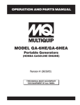
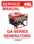
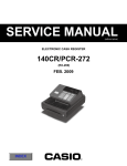
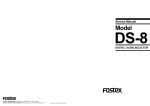
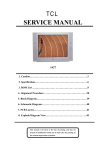
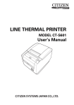
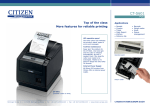
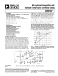
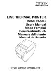
PH-50
Service Manual
Model
PH-50
Headphone Amp Distributor
1
PH-50
CAUTION:
CAUTION
TO PREVENT ELECTRIC SHOCK, MATCH
RISK OF ELECTRIC SHOCK
DO NOT OPEN
WIDE BLADE OF PLUG TO WIDE SLOT,
FULLY INSERT.
ATTENTION:
CAUTION: TO REDUCE THE RISK OF ELECTRIC SHOCK,
POUR ÉVITER LES CHOCS ÉLECTRIQUES,
DO NOT REMOVE COVER (OR BACK).
INTRODUIRE LA LAME LA PLUS LARGE DE
NO USER-SERVICEABLE PARTS INSIDE.
LA FICHE DANS LA BORNE CORRESPONDANTE DE LA PRISE ET POUSSER
REFER SERVICING TO QUALIFIED SERVICE PERSONNEL.
JUSQU' AU FOND.
The lightening flash with arrowhead symbol,
within an equilateral triangle, is intended to
alert the user to the presence of uninsulated
“dangerous voltage” within the product's enclosure that may be of sufficient magnitude to
constitute a risk of electric shock to persons.
The exclamation point within an equilateral
triangle is intended to alert the user to the
presence of important operating and maintenance (servicing) instructions in the literature
accompanying the appliance.
“WARNING”
“TO REDUCE THE RISK OF FIRE OR ELECTRIC SHOCK,
DO NOT EXPOSE THIS APPLIANCE TO RAIN OR MOISTURE.”
SAFETY INSTRUCTIONS
1.
2.
3.
4.
5.
6.
Read instructions - All the safety and operating instructions should be read before the appliance is operated.
Retain instructions - The safety and operating instructions
should be retained for future reference.
Heed warnings - All warnings on the appliance and in the
operating instructions should be adhered to.
Follow instructions - All operating and use instructions
should be followed.
Water and Moisture - The appliance should not be used
near water - for example, near a bathtub, washbowl,
kitchen sink, laundry tub, in a wet basement, or near a
swimming pool, and the like.
Carts and Stands - The appliance should be used only
with a cart or stand that is recommended by the manufacturer.
9.
10.
11.
12.
13.
14.
15.
7.
8.
2
An appliance and cart combination should be moved with
care. Quick stops, excessive force, and uneven surfaces
may cause the appliance and cart combination to overturn.
Wall or Ceiling Mounting - The appliance should be
mounted to a wall or ceiling only as recommended by the
manufacturer.
Ventilation - The appliance should be situated so that its
location or position does not interfere with its proper ventilation. For example, the appliance should not be situated on a bed, sofa, rug, or similar surface that may block
the ventilation openings; or, placed in a built-in installation, such as a bookcase or cabinet that may impede the
flow of air through the ventilation openings.
16.
17.
Heat - The appliance should be situated away from heat
sources such as radiators, heat registers, stoves, or other
appliances (including amplifiers) that produce heat.
Power Sources - The appliance should be connected to a
power supply only of the type described in the operating
instructions or as marked on the appliance.
Grounding or Polarization - The precautions that should
be taken so that the grounding or polarization means of
an appliance is not defeated.
Power Cord Protection - Power supply cords should be
routed so that they are not likely to be walked on or
pinched by items placed upon or against them, paying
particular attention to cords at plugs, convenience receptacles, and the point where they exit from the appliance.
Cleaning - The appliance should be cleaned only as recommended by the manufacturer.
Nonuse Periods - The power cord of the appliance should
be unplugged from the outlet when left unused for a long
period of time.
Object and Liquid Entry - Care should be taken so that
objects do not fall and liquids are not spilled into the enclosure through openings.
Damage requiring Service - The appliance should be serviced by qualified service personnel when:
A. The power supply cord or the plug has been damaged;
or
B. Objects have fallen, or liquid has been spilled into the
appliance; or
C. The appliance has been exposed to rain; or
D. The appliance does not appear to operate normally or
exhibits a marked changed in performance; or
E. The appliance has been dropped, or the enclosure
damaged.
Servicing - The user should not attempt to service the appliance beyond that described in the operating instructions. All other servicing should be referred to qualified
service personnel.
PH-50
TABLE OF CONTENTS
1. SPECIFICATIONS . . . . . . . . . . . . . . . . . . . . . . . . . . . . . . . . . . . . . . . 4
2. CONTROLS, INDICATORS AND CONNECTORS . . . . . . . . . . . . 5
3. EXPLODED VIEW, PCB ASSEMBLY AND PARTS LIST . . . . . . 6
4. CIRCUIT & BLOCK DIAGRAMS . . . . . . . . . . . . . . . . . . . . . . . . 10
NOTES
* Parts List and circuit diagrams are given in this manual to assist the service technician in maintaining the Model PH-50.
* The following accessories are supplied with PH-50 as the standard accessories.
Owner's manual
: 8288384000 (for export model)
Owner's manual
: 8288385000 (for domestic model)
* Following is the packing material for the Model PH-50.
PACKING SIDE A PH-50 : 8228445000
CARTON BOX PH-50
: 8228721000
CAUTION
Parts marked with this sign are safety critical components. They must always be replaced with identical components.
Refer to the Fostex Parts List and ensure exact replacement.
3
PH-50
1. SPECIFICATIONS
INPUT SECTION
INPUT (Balanced)
Connector
Input level
Impedance
INPUT (Unbalanced)
Connector
Input level
Impedance
CHANNEL INPUT
Connector
Input level
Impedance
AUX INPUT
Connector
level
Impedance
XLR ( Hot : Pin 2 ) / Stereo phone ( Hot : tip )
+4dBu / -10dBV(switchable)
10 kΩ or more
RCA pin
-10dBV
10 kΩ or more
RCA pin
-10dBV
10 kΩ or more
RCA pin
-10dBV
10 kΩ or more
OUTPUT SECTION
PHONES 1-5
Connector
Max. Output Level
Load Impedance
Frequency Response
S/N
Distortion
CASCADE OUT
Connector
Output level
Frequency Response
S/N
Distortion
Click Noise (Power on / off)
Shock Noise
Peak LED Indication
Stereo phone
500 mW or more ( 32 Ω load, Distortion 3.0 % or less )
8 ~ 32 Ω
30 ~ 20 kHz ± 2dB ( 32 Ω load, 1kHz, 200 mW )
-65dBV or less (DIN AUDIO, OUTPUT VR : MIN)
-80dBV or less ( IHF-A, OUTPUT VR : MIN)
0.1 % or less ( 32 Ω load, 1kHz, 200 mW )
RCA pin
-10dBV ± 3dB (INPUT VR : CAL )
30 ~ 20 kHz ± 1dB
-85dBV or less (DIN AUDIO, OUTPUT VR : MIN)
-90dBV or less ( IHF-A, OUTPUT VR : MIN)
0.05 % or less ( 1kHz, -10dBV )
-20dBVp-p or less (OUTPUT VR : MIN)
-40dBVp-p or less (Measure noise level when one side of appliance
is dropped 3 times from 5 cm height.)
+7dBV ± 3dB
GENERAL
Dimensions
Weight
Power supply
JPN
USA/CND
EUR/UK
Power consumption
210 (W) × 200 (D) × 43 (H) mm
1.9 kg
100 VAC, 50/60 Hz
120 VAC, 60 Hz
230 VAC, 50/60 Hz
8W
* Specifications and appearance are subject to change without notice for product improvement.
4
PH-50
2. CONTROLS, INDICATORS & CONNECTORS
< Front Panel >
2
1
5
5
5
5
3
4
5
5
PH-50
HEADPHONE AMP DISTRIBUTOR
0
10
0
1
10
0
10
0
3
2
10
0
4
10
5
0
ST MONO
PHONES
5
0
CAL
10
INPUT
5
1.
2.
3.
4.
POWER
PEAK
10
AUX IN
6
Headphone output level control knob [PHONES 1-5]
AUX input level control knob [AUX IN]
Peak LED [PEAK]
Power LED [POWER]
5.
6.
7.
8.
7
8
Headphone jacks [PHONES 1-5]
Input image position selector switch [ST/MONO]
Input master level control knob [INPUT]
Power switch [POWER]
< Rear Panel >
9
1
2
CHANNEL IN
3
10
INPUT
(-10dBV)
4
5
L
(+4dBu/-10dBV)
R
XLR PHONE
2
T
HOT
3
R
COLD
1
S
GND
L
L (-10dBV) R
CASCADE OUT
11
9.
10.
11.
12.
L
(-10dBV)
R
INPUT
L/MONO
AUX IN
12
Channel input jacks [CHANNEL IN 1-5]
Balanced input connector (XLR) [INPUT]
Cascade output jack [CASCADE OUT]
Unbalanced input jack [INPUT]
R
+4dBu
R
-10dBV
(-10dBV)
13
14
15
13. AUX input jacks [AUX IN]
14. Balanced input level selector switch [-4dBu/-10dBV]
15. Balanced input connector (Stereo phone) [INPUT]
5
PH-50
3. EXPLODED VIEW, PCB ASSEMBLY AND PARTS LIST
PH-50 OVERALL EXPLODED VIEW & PARTS LIST
Ref. No.
Part No.
Ref. No.
8
Description
1
2
8221262000 CASE, COVER, PH-50
8221264000 PANEL, FRONT, PH-50
3
4
8274174000 PCB Assy, MAIN, PH-50
8650800000 CORD, AC, USA/CND
Part No.
Description
8274175000 PCB Assy, VR, PH-50
9
10
8226198003 ROTARY, KNOB(C), G
8226198001 ROTARY, KNOB(A), R
11
8242256003 TRANS, POWER, 120V
8650801000 CORD, AC, EUR
8650802000 CORD, AC, UK
8242256006 TRANS, POWER, 230V~
8242256010 TRANS, POWER, 100V
8221263000 CHASSIS, MAIN, PH-50
12
5
8650803000 CORD, AC, JPN
8207000208 BUSHING, SR-4N-4
13
8253014007 SW, WL, PUSH, POWER, SDDLB-SPST
6
7
8218775001 INSULATION SHEET, PH-50
8228775002 INSULATION SHEET B, PH-50
14
15
8207000318 PLASTY-FOOT, 3725
8226228000 BUTTON, PUSH, POWER
BBT 3x6 BZn
BBT 3x6 BZn
BBT 3x6 BZn
BBT 3x6 BZn
BBT 3x6 BZn
BBT 3x8 BZn
BBT 3x8 BZn
BBT 3x8 BZn
6
B 3x6 CZn
BBT 3x6 BZn
PH-50
PH-50 Parts List
• MAIN/VR PCBs
RESISTORs
ICs
Ref. No.
Part No.
Description
U101~501 8236035803 IC, µPC4570HA
U102~502 8236046000 IC, NJM386BD
U152~552 8236046000 IC, NJM386BD
U601
U602
8236035803 IC, µPC4570HA
8236035803 IC, µPC4570HA
U605
U651
8236035803 IC, µPC4570HA
8236035803 IC, µPC4570HA
U701
U801
8236035803 IC, µPC4570HA
8236032005 IC, REGULATOR, NJM78M12FA
U802
8236034705 IC, REGULATOR, 79M12FA
Ref. No.
Part No.
Description
R101~501 8240284001 VR, RK09K120A1NA, 5KΩA x 2
R110~510 8230138393 HT, CARBON, 1/4W, 39KΩ, 5%
R111~511 8230138393 HT, CARBON, 1/4W, 39KΩ, 5%
R112~512 8230138104 HT, CARBON, 1/4W, 100K, 5%
R113~513 8230138332 HT, CARBON, 1/4W, 3.3KΩ, 5%
R114~514 8230138332 HT, CARBON, 1/4W, 3.3KΩ, 5%
R115~515 8230138332 HT, CARBON, 1/4W, 3.3KΩ, 5%
R116~516 8230138103 HT, CARBON, 1/4W, 10KΩ, 5%
R117~517 8230138100 HT, CARBON, 1/4W, 10Ω, 5%
R118~518 8230111568 H, METAL, 5.6Ω, 5%
R119~519 8230138332 HT, CARBON, 1/4W, 3.3KΩ, 5%
R150~550 8230138393 HT, CARBON, 1/4W, 39KΩ, 5%
R151~551 8230138393 HT, CARBON, 1/4W, 39KΩ, 5%
TRANSISTORs
Ref. No. Part No.
Q601
8234108900
Description
TR, 2SD1858, QR, T
Q602
Q603
8234108900
8234108800
TR, 2SD1858, QR, T
TR, 2SB1237, PQR, T
Q604
Q801
8234108900
8234107600
TR, 2SD1858, QR, T
TR, 2SC4549, NEC
DIODEs
Ref. No.
Part No.
D601
8234106500
Description
OPT, LED, RT3-222HCS
D602
D603
8234500700
8234500700
D, HT,1SS136
D, HT, 1SS136
D751
D752
8234500700
8234106500
D, HT, 1SS136
OPT, LED, RT3-222HCS
D753
D754
8234500700
8234500700
D, HT, 1SS136
D, HT, 1SS136
D801
D802
8234108700
8234106500
D, RB151
OPT, LED, RT3-222HCS
R152~552 8230138104 HT, CARBON, 1/4W, 100KΩ, 5%
R153~553 8230138332 HT, CARBON, 1/4W, 3.3KΩ, 5%
R154~554 8230138332 HT, CARBON, 1/4W, 3.3KΩ, 5%
R155~555 8230138332 HT, CARBON, 1/4W, 3.3KΩ, 5%
R156~556 8230138103 HT, CARBON, 1/4W, 10KΩ, 5%
R157~557 8230138100 HT, CARBON, 1/4W, 10Ω, 5%
R158~558 8230111568 H, METAL, 5.6Ω, 5%
R159~559 8230138332 HT, CARBON, 1/4W, 3.3KΩ, 5%
R601, 602 8240284001 VR, RK09K120A1NA, 5KΩA x 2
R610, 650 8230138104 HT, CARBON, 1/4W, 100KΩ, 5%
R611, 651 8230138103 HT,CARBON, 1/4W, 10KΩ, 5%
R612, 652 8230138103 HT, CARBON, 1/4W, 10KΩ, 5%
R613, 653 8230138103 HT, CARBON, 1/4W, 10KΩ, 5%
R614, 654 8230138103 HT, CARBON, 1/4W, 10KΩ, 5%
R615, 655 8230138104 HT, CARBON, 1/4W, 100KΩ, 5%
R616, 656 8230138104 HT, CARBON, 1/4W, 100KΩ, 5%
R617, 657 8230138103 HT, CARBON, 1/4W, 10KΩ, 5%
R618, 658 8230138103 HT, CARBON, 1/4W, 10KΩ, 5%
R619, 659 8230138822 HT, CARBON, 1/4W, 8.2KΩ, 5%
R620, 660 8230138822 HT, CARBON, 1/4W, 8.2KΩ, 5%
R621, 661 8230138822 HT, CARBON, 1/4W, 8.2KΩ, 5%
R622, 662 8230138822 HT, CARBON, 1/4W, 8.2KΩ, 5%
R623, 663 8230138103 HT, CARBON, 1/4W, 10KΩ, 5%
R624, 664 8230138103 HT, CARBON, 1/4W, 10KΩ, 5%
R625, 665 8230138102 HT, CARBON, 1/4W, 1KΩ, 5%
R626, 666 8230138104 HT, CARBON, 1/4W, 100KΩ, 5%
R627, 667 8230138393 HT, CARBON, 1/4W, 39KΩ, 5%
R628, 668 8230138393 HT, CARBON, 1/4W, 39KΩ, 5%
R629, 669 8230138332 HT, CARBON, 1/4W, 3.3KΩ, 5%
R630, 670 8230138103 HT, CARBON, 1/4W, 10KΩ, 5%
R631, 671 8230138103 HT, CARBON, 1/4W, 10KΩ, 5%
R632, 672 8230138393 HT, CARBON, 1/4W, 39KΩ, 5%
R633, 673 8230138101 HT, CARBON, 1/4W, 100Ω, 5%
7
PH-50
MISCELLANEOUS
CAPACITORs
ALU = Electrolytic
CER = Ceramic type
Ref. No.
CN803
Part No.
Description
8745503003 CONN, XH 3P (87003048)
PES = Mylar type
Description
J101~601
J602
8245337000 CONN, PHONE JACK, STEREO
8245268002 CONN, PL, JACK, XLR31, NC3FAH2
C101~501 8232050100 CER, 50V, 10PF, +-.5PF, SL
C102~502 8232804104 CER, 25V, 0.1µF, +80-20%, YF
J603
J651
8245311004 CONN, RCA, 4P, YKC21-3084
8245337000 CONN, PHONE JACK, STEREO
C103~503 8232901102 PES, 50V, 0.001µF, 5%, AMZV
C104~504 8232143337 ALU, 16V, 330µF, 20%, SME-VB
J652
J701
8245268002 CONN, PL, JACK, XLR31, NC3FAH2
8245311006 CONN, RCA, 6P, YKC21-3154
C105~505 8232142476 ALU, 10V, 47µF, 20%, SME-VB
C107
8232804104 CER, 25V, 0.1µF, +80-20%, YF
J706
8245311001 CONN, RCA, 1P, YKB11-0273
C108
8232804104 CER, 25V, 0.1µF, +80-20%, YF
C109~509 8232901473 PES, 50V, 0.047µF, 5%, AMZV
S601
S602
8253467000 SW, SS010-P022MAM-PA9
8253467000 SW, SS010-P022MAM-PA9
C151~551 8232050100 CER, 50V, 10PF, +-.5PF, SL
C153~553 8232901102 PES, 50V, 0.001µF, 5%, AMZV
W601
8277473001 CORD, SCN-SCN, 8P x 200
C154~554 8232143337 ALU, 16V, 330µF, 20%, SME-VB
C155~555 8232142476 ALU, 10V, 47µF, 20%, SME-VB
W602
W603
8277473001 CORD, SCN-SCN, 8P x 200
8277473002 CORD, SCN-SCN,10P x 200
Ref. No.
Part No.
C159~559 8232901473 PES, 50V, 0.047µF, 5%, AMZV
C307
8232804104 CER, 25V, 0.1µF, +80-20%, YF
C308
8232804104 CER, 25V, 0.1µF, +80-20%, YF
C601, 651 8232144226 ALU, 25V, 22µF, 20%, SME-VB
C602, 652 8232144226 ALU, 25V, 22µF, 20%, SME-VB
C603, 653 8232144226 ALU, 25V, 22µF, 20%, SME-VB
C604, 654 8232050101 CER, 50V, 100PF, 5%, SL
C605, 655 8232050101 CER, 50V, 100PF, 5%, SL
C606, 656 8232804104 CER, 25V, 0.1µF, +80-20%, YF
C607, 657 8232144226 ALU, 25V, 22µF, 20%, SME-VB
C608, 658 8232050100 CER, 50V, 10PF, +-.5PF, SL
C610, 660 8232144226 ALU, 25V, 22µF, 20%, SME-VB
C611, 661 8232050100 CER, 50V, 10PF, +-.5PF, SL
C612, 662 8232804104 CER, 25V, 0.1µF, +80-20%, YF
C614, 664 8232144226 ALU, 25V, 22µF, 20%, SME-VB
C615, 665 8232050100 CER, 50V, 10PF, +-.5PF, SL
C617, 667 8232144226 ALU, 25V, 22µF, 20%, SME-VB
C620
C621
8232153225 ALU, 50V, 2.2µF, 20%, BP, SME-VB
8232146225 ALU, 50V, 2.2µF, 20%, SME-VB
C622
8232146225 ALU, 50V, 2.2µF, 20%, SME-VB
C701~705 8232144226 ALU, 25V, 22µF, 20%, SME-VB
C751~753 8232804104 CER, 25V, 0.1µF, +80-20%, YF
C801
8232096108 ALU, 25V, 1000µF, 20%, SME-VB
8
C802
C803
8232096338 ALU, 25V, 3300µF, 20%, SME
8232096108 ALU, 25V, 1000µF, 20%, SME-VB
C804
C805
8232804104 CER, 25V, 0.1µF, +80-20%, YF
8232804104 CER, 25V, 0.1µF, +80-20%, YF
C806
C807
8232144226 ALU, 25V, 22µF, 20%, SME-VB
8232144226 ALU, 25V, 22µF, 20%, SME-VB
C808
C809
8232901473 PES, 50V, 0.047µF, 5%, AMZV
8232901473 PES, 50V, 0.047µF, 5%, AMZV
C810
8232096108 ALU, 25V, 1000µF, 20%, SME-VB
8207012800 HEATSINK, PC1115-25
PH-50 PCB PATTERN DRAWING
PH-50
9
PH-50
10
4. CIRCUIT & BLOCK DIAGRAMS
+B2
R116
10k
D802
L-934ID-5V
C601
25V/22u
J603B
RCA 6P
3
UNBAL.IN L
-10dBV
C605
100p
R610
100k
J601
2
R618
1
HTJ064
+4dBu/-10dBV
3
J602
CANNON
R612
10k
C603
25V/22u
R615 R617
10k
100k
R616
100k
R620
8.2k
-B2
R632
3
U651A
4570A
1
R625
1K
5
R628
R627
39k
R626
100k
J604D
RCA 4P
6
-10dBV
2
1
HTJ064
3
2
J652
CANNON
C662
0.1u
1
R666
100k
R660
8.2k
8
R664
10k
7
6
25V/22u
CHANNEL IN 2
-10dBV
CHANNEL IN 3
-10dBV
CHANNEL IN 4
-10dBV
CHANNEL IN 5
-10dBV
J701
RCA 6P
8
7
39k
+B2
7
6
CASCADE OUT R
-10dBV
R702
100k
25V/22u
4
1
6
C201
8
U651B
4570A
1
1
2
3
4
5
6
7
8
1
2
3
4
5
6
7
8
R703
100k
25V/22u
7
R672
7
0.001u
R250
39k
R153
3.3k
R670
10k
6
8
R214
3.3k
5
R255
3.3k
1
C301
R310
39k
R669
8
R671
3.3k
R253
3.3k
R315
3.3k
2
4
R311
39k
25V/22u
U301A
4570A
5
C302
0.1u
-B2
5
R350
39k
R352
4
100k
9
6
8
R355
3.3k
C353
0.001u
1
2
3
4
R704
100k
R705
100k
25V/22u
J701
RCA 6P
9
R353
3.3k
R638
Q601
D1858
W602
62903579
2.2k
3.3k
R415
3.3K
-B2
Q603
B1237
3.3k
R413
3.3k
C402
0.1u
10p
R452
R450
39k
R451
39k
6
D601
L-934ID-5V
100k
4
R401
5kAA
3
+B2
9
8
7
2.2k
R639
0.001u
1
2
3
4
3
XH3P
C809
G G2 8
- P 7
+ B 6
E O 5
G G2
- P
+ B
E O
D602
1SS133
2
4
1
C620
50V/2.2u BP
3 D801
RB151
0.0047
Q801
C4549
R454
3.3k
C453
R455
3.3k
0.001u
R637
10k
R805
100
D603
1SS133
Q604
D1858
C621
50V/2.2u
3
C810
25V/1000u
G
2
R512
C804
0.1u
C806
25V/22u
3
25V/3300u
4
C801
R511
39k
25V/1000u
1
R802
F2.2
3
2
G
1
IN OUT
U802
79M12AHF
C551
R551
39k
R550
39k
-B2
R552
7
6
R803
100
R804
100
R358
5.6
C404
16V/330u
R418
5.6
R417
10
C308
0.1u
C409
0.047
G G2
- P
+ B
E O
8
7
6
5
R514
3.3k
C454
16V/330u
R458
5.6
C504
16V/330u
R518
5.6
R457
10
U502
C503
R515
3.3k
R453
3.3k
1
2
3
4
+B1
G G2 8
- P 7
+ B 6
E O 5
R517
10
386B
C505
10v/47u
R513
3.3k
R554
3.3k
C752
0.1u
C509
0.047u
R555
3.3k
5
1
2
3
4
G G2 8
- P 7
+ B 6
E O 5
386B
C555
10v/47u
7
1
6
2
R553
3.3k
R519
3.3k
R559
3.3k
U552
C553
0.001u
C502
0.1u
10p
4
R501
5kAA
3
HTJ064
R516
10k
U501A
4570A
100k
J401
3
1
PHONES OUT 4
C459
0.047u
R556
10k
+B2
9
8
U501B
4570A
R419
3.3k
2
R459
3.3k
6
2
5
C807
25V/22u
C805
0.1u
C354
16V/330u
R357
10
C455
10v/47u
1
100k
-B2
C803
25V/1000u
1
2
3
4
+B2
R510
39k
C802
HTJ064
U452
7
10p
C501
J301
3
1
PHONES OUT 3
+B1
386B
0.001u
U801
78M12AHF
1
IN OUT
R319
3.3k
2
C359
0.047u
8
7
6
5
386B
2
U401B
4570A
+B1
C622
50V/2.2u
R636
100k
R634
27k
R801
F2.2
C808
0.0047
C309
0.047u
0.1u
R456
10k
U401A
4570A
+B2
CN802
1
2
C307
U402
C403
2
5
C451
R641
Q602
D1858
1
4
R318
5.6
R317
10
R359
3.3k
C405
10v/47u
5
R640
J701
RCA 6P
6
R410
39k R411
39k
C304
16V/330u
+B1
8
G G2 7
- P 6
+ B 5
E O
C355
10v/47u
100k
3
1
2
3
4
5
6
7
8
R258
5.6
R257
10
25V/22u
1
2
3
4
5
6
7
8
C254
16V/330u
R416
10k
R414
3.3k
C705
HTJ064
C259
0.047u
386B
+B2
J603
RCA 4P
2
J201
3
1
PHONES OUT 2
U352
6
10p
R412
8
7
6
5
R356
10k
7
C703
C704
G G2
- P
+ B
E O
C305
10v/47u
R354
3.3k
R219
3.3k
2
R259
3.3k
386B
2
U301B
4570A
C401
C209
0.047u
0.1u
U302
1
2
3
4
1
R301
5kAA
3
+B2
7
1
2
3
4
5
6
7
8
9
10
W603
62903580
10p
C351
R351
39k
1
2
3
4
5
6
7
8
9
10
R313
3.3k
1
3
C667
R218
5.6
R217
10
C108
R316
10k
0.001u
10p
100k
C204
16V/330u
+B1
8
7
6
5
C255
10v/47u
R314
3.3k
+B2
9
G G2
- P
+ B
E O
386B
386B
2
U201B
4570A
R312
U701B
4570A
1
2
3
4
C303
U602B
4570A
R158
5.6
U252
6
3
+B2
9
8
C154
16V/330u
R157
10
U202
1
2
3
4
C253
0.001u
7
4
R201
5kAA
HTJ064
C159
0.047u
R256
10k
R254
3.3k
100k
R673
100
0.001u
R213
3.3k
C202
0.1u
J101
3
1
PHONES OUT 1
R216
10k
R215
3.3k
10p
6
8
7
6
5
2
R252
7
G G2
- P
+ B
E O
C205
10v/47u
-B2
R119
3.3k
2
R159
3.3k
C155
10v/47u
2
U201A
4570A
C251
0.1u
R118
5.6
U152
1
2
3
4
6
8
U101B
4570A
5
W601
62903579
39k
9
1
4
R117
10
C109
0.047u
C107
386B
10p
3
+B2
10p
R635
100k
To Transformer
C153
R155
3.3k
100k
R211
39k
R251
39k
C660
25V/22u
R665
1K
25V/22u
R210
39k
C702
J603
RCA 4P
5
1
CASCADE OUT L
-10dBV
25V/22u
J701
RCA 6P
2
1
9
6
C701
R701
100k
J701
RCA 6P
5
4
7
2
7
1
+B2
C661
10p
5
6
9
4
100p
C665
R667
5
4
R101
5kAA
3
100k
C104
16V/330u
R156
10k
R154
3.3k
10p
+B1
G G2 8
- P 7
+ B 6
E O 5
386B
C105
10v/47u
C102
0.1u
R152
1
2
3
4
R113
3.3k
U101A
4570A
+B2
R668 39k
C664
2
5
C617
R601
5kAA
10k
CHANNEL IN 1
-10dBV
R150
39k
R602
5kAA
4
3
10k
2
+B2
R662
39k
C657
25V/22u
U601B
4570A
C654
R657
10k
4
+4dBu
9
6
25V/22u
1
4
R151
39k
5
3
2
3
5
R661
8.2k
R659
8.2k
-10dBV
6
5
1
6
S602B 4
SSSF 2-2
C658
10p
S601B
SSSF 2-2
+B2
C652
25V/22u
R655
100k
J605
RCA JACK SW
3
AUX IN R
-10dBV
1 2
S602A
SSSF 2-2
R663
10k
10k
R658
7
R654
10k
R656
100k
3
R111
39k
-B2
C612
0.1u
R631
3.3k
-B2
C653
R115
3.3k
C203
C655
100p
R652
10k
R751
220k
R212
25V/22u
R653
10k
D753
1SS133
R752
27k
R110
39k
R758
0
7
3
BAL.IN L
+4dBu/-10dBV
U102
0.001u
100k
+B2
R629
2
5
R651
10k
C751
0.1u
R755
4.7k
U701A
4570A
1
4
C651
R650
100k
J651
3
R757
100
-B2
R112
D754
1SS133
39k
+B2
C614
25V/22u
J604B
RCA 4P
3
-10dBV
6
U605B
4570A
5
10p
-B2
AUX IN L
9 7
8
R633
100
2
4
R630
10k
0.1u
C656
-B2
D751
1SS133
C151
1
3
R754
100k
U602A
4570A
C610
25V/22u
C103
R114
3.3k
10p
39k
+B2
2
4
C604
100p
C615
10p
C611
C101
+B2
R756
4.7k
3
4
5
R624 10k
R622
39k
C607
25V/22u
C606
0.1u
2
+B2
1
+4dBu
2
4
5
R614
10k
1
U601A
4570A
U605A +B2
4570A
1
C753
0.1u
-B2
R621
8.2k
R619
8.2k
-10dBV
3
1
3
R613
10k
2
10k
2
+B2
C602
25V/22u
C608
10p
S601A
SSSF 2-2
R611
10k
3
BAL.IN L
D752
L-934ID-5V R759
4.7k
R623
10k
R753
27k
C554
16V/330u
C559
0.047u
R557
10
R558
5.6
2
J501
3
1
PHONES OUT 5
HTJ064
BLOCK DIAGRAM
PH-50
11
PH-50
FOSTEX CORPORATION 3-2-35 Musashino, Akishima, Tokyo, Japan 196-0021
FOSTEX CORPORATION OF AMERICA 15431 Blackburn Ave., Norwalk, CA 90650, U.S.A.
12
© PRINTED IN JAPAN JUNE 1998 8288774000