1
illonufotturer
Propeller
Ihe llorld's0ldesrAircoft
lla/*t1*
v
.-fE'
,:N,'
,-sVICE
[,lAl{UAt
t , ;
lft0Dtt,fF_
flxtD - PITGH
PROPTTTTR
'j
ilA]tUtACTURtNG
C0tttpAlfy
I N T E R N A T I O N AALI R P O R I
ST.PETERSBURG,
32, FIORIDA
rt
;'Y
' )
;..Jt
I
I
I
$i
ol
F:
o.'
"9$
;!
FT
ti
Ji
,u
TI
.:
:l
, ; |
--it
l' ._-/,
I
SERVICE MANUAT
Model Fl
Fixed-P itch Propel lers
INTRODUCTION
This manual contains routine inspection,
meintenenee,
overhaul, and minor repair procedures which can be aecomplished
by propeller servicing facilities.
These instructions
are intended
to suPplement the critetia
set forth in Civil Air Regulations part 18
and Civil Aeronautics Manual 18. In no case ere they to be construed
or interpreted
es overriding
or contradictory
to the material in the
regulations or manual.
t
The use of this manual by any propeller servicing facility
shall
not, under eny circrrmstances be lnterpreted
or construed as en approval
of the facility
by Flottorp Manufacturing Coupany.
This manual revised September 26, 1962, and the following
have been approved by the FAA.
addenda
FAA Approrred.
Chief , Engr.
Approval
-1-
\*-
& Ivlfg, Braneh
Date
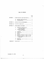
TABLE OF CONTENTS
Page
SECTION I
Specifications
A.
B.
and Deseription. . . . . .
3
GeneralSpecifications... .......
Installations...................
3
3
SECTION II
Service Tools and Equipment.........
3
SE C T ION III
P g r i o d i c I n s p e c t i o n. . . . . . . . . . . . . . . .
4
SECTION IV
M a i n t e n g n c ea n d R e p a i r . . . . . . . . . . . . .
4
A.
B.
4
5
C.
C l e a n i n g. . . . . . . . . . . . . . . . . . . . . . .
5
D.
E.
I n s p e c t i o n. . . . . . . . . . . . . . . . . . . . .
R e p a i r s. . . . . . . . . . . .
.......o
Checking Propeller Track in Shop
Checking Prope1ler Track on the
Aircraft...................
6
6
H.
P a i n t i n g. . . . . . . o . . . . . . . . . . . . . . .
l
I.
B a l a n e i n g. . . . . . . o . . . . . . . . . . . . . .
8
F.
G.
SECTION V--
Propeller Installation,
0-320-D2B
E n g i n e. . . . . . . . . . . .
Propeller Removal,
0-320-D2B
Ergine ............
Parts List
7
7
9
September 26, L962
-2-
.{
L
-l
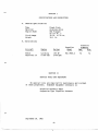
SECTION I
SPECIFICATIONS ATID DESCRIPTION
A.
G e n e ra l
Sp e c i f i c a ti ons
Type
Material
Engine Shaft
Fi xed-P i tch
Aluminuur Al loy
SAE Flanged
A S L27 N o. 2
50 in. to 70 in.
30.5 lb.
Pitch Range
Weight
B.
Installations
Propeller
D i a m et er
P ropel l er
Aircraft
Engine
Rating
Beeeh
Musketeer 23
Lycoming
O-320-D2B
160 HP
2700 RPM
Model
FlC 7660-2
fr
74
SECTIONII
SERVTCETOOLSAr{D EQUIPMENT
No special tools
of these propellers.
are required for maintenance and overhaul
Standard equipment necessary is:
Propeller Assembly Tab1e
Suspension Type Propeller Balancer
September 26, 1962
-3-
---
t
74
S EC TION III
PERIODIC INSPECTION
NATURE OF INSPECTION
S ec ur it y
o f m o u n ti n g
bolts safetied
Minor
nicks,
INSPECTION TIME
a n d m o u n t i ng
scratches,
Postfl ight
and cracks
Postf 1ight
CAUTION
Due to the high stresses to which the
propeller
blades ere subjeeted, their
careful maintenance is vitally
important,
particularly
on the leading edge of each
b l a d e fro m th e ti p i nboard for approxi matel y
8 inches.
A11 nicks and scratches must be
repaired before the airplane
is flor^nr. Nicks
and scratches set up coneentrations
of stress
which can exceed the strength
of the blade
material;
the result will
be a crack and premature failure
of the blade
Corrosion, cracks nicks,
dents beyond permissible
and
limits
30 hours
O v er haul
At engine overhaul
SECTION IV
MAINTENANCE AI\D REPAIR
In general,
all instruetions
and procedures outlined
in CAM 18 for
all inspection,
maintenanee, and repair
should be adhered to.
Balancing
the propeller
should be performed by an FAA certificated
propeller
repair
station
sinee equipment neeessary to accomplish the aecuracy required
is
not normally available
to line maintenance personnel.
A.
Propeller
1.
Installation,
Without
0-320-D2B Engine
Spinner
a.
R o ta te th e
ligns with
b.
Slide the propeller
onto the engine shaft indexing it so that
the blades lie aPprox. at the 5 o'clock and 11 o'clock positions.
c.
Install
evenly,
d.
Secure the bolts
S ept em ber 2 6 ,
e n g i n e unti l
the TC #L mark on the starter
the dot on the engine starter
housing.
the 6 propeller
retaining
bolts
a n d to rq u e to 300 i neh-pounds.
with
safety
L962
-4-
wire.
and washers,
gear
tighten
a-
2.
B.
a.
Rotate the engine until the TC #L mark on the starter
with the dot on the engine starter housing.
b.
Sl i d e th e s pi nner rear bul khead onto the engi ne
s o th a t th e tabs w hi ch have the corners cut off
the 6 o'c1ock and the L2 o'clock positions.
c.
Sl i d e th e p r opel l er
onto the engi ne shaft
i ndexi ng
i t so t hat
the blades 1ie approx. at the 5 o'clock
and 11 o'clock positions.
d.
Insert
the 6 propeller
retaining
bolts and washers into the
h o l e s i n th e spi nner front
bul khead,
and sl i de
the assem bly
onto the propeller,
aligning
the bulkhead cutouts with the
blades.
Tighten the bolts evenly and torque to 300 inch-pounds.
e.
Secure the bolts
f.
slide
the spinner dome onto the bulkheads,
1 0 re ta i n i n g
screw s and w ashers.
Propeller
1.
2.
C.
W i t h B e e c h 1 6 9 - 9 1 0 0 3 0S p i n n e r A s s y .
with
safety
gear aligns
shaft indexing
l i e appr ox. at
it
wire.
and install
the
Removal, 0-320-D2B Engine
Without
Spinner
a.
Remove the 6 propeller
b.
Remove the propeller
retaining
from
bolts
the engine
and washers.
shaft.
With Beech 169-910030 Spinner Assy.
a.
R e mo v e th e
and remove
b.
Remove the 6 propeller
retaining
s p i n n e r fro n t
bul khead.
C.
R e mo v e th e p ropel l er
shaft.
10 spi nner
the dome.
dome retai ni ng
and the
bolts
spi nner
screw s
and w ashers,
and washers,
rear
bul khead
and the
from
t he engine
Cleaning
For eleanitg,
use warm fresh water and soap, unleaded gasoline,
or
kerosene, and suitable
brushes or cloths.
After
the blades have been
cleaned, all cleaning
substances must be i mmedi atel y
removed.
Soap in
a n y fo rm s h o u l d b e removed by thoroughl y
ri nsi ng
w i th fresh w at er ,
after which all steel surfaces should be dried and eoated with clean
engine oil.
S c ra p e rs , por^rer buf f ers , steel brushes,
and any other t ools
or substances that will
scratch or otherwise mar the surface must not
be used on blades.
In special eeses where a high polish is desired, a
good metal aircraft
polish may be used, however, upon completion of the
polishing,
all traees of polish should be immediately removed.
In no
instance shal1 the blades be polished with a power buffer.
September 26, L962
-5-
*',ffi,fffi*ffi
.ai
>rl
.
I t.,
Sl.O.,.,tp
u ;t
o
{
7.
o'
(,|l \fl \'
't
(-)
0
v
fi
6)
rfl
N
nl
tlJN
7
,J(
T
)
O
N ul O 0\q o \
t ^ l - q . W q h u l St
C)
n
0
I
7t
]1r
\ nrn
I \s
I
1
tl
r
b
h
. t r W $ S r r t
{ ! N l
o\ 'D F'
$ il {.bt\l
D f,''
o A d o o
rrJ
ln
t
t
t
t
I
l
t--:l
t
-
.
t
ll
I|
|ll ..,
r
I t
'
I
'lI ' t
>
t - ,
li ;
c,
-t
r
m
T
l -
l -
-T_
-
I
b
T
N
o
n
!
th
F
lll'
II
-
r f l m
lA
4 .
z
rn
-'lI
HS',
m.
r
r,
*
t',
rf
m
, t $ { J 3? $
\9
Lil J
rI' f$
),,
.a^
\
+
o c /
t
T
*\
I
r|l
x
g
\
.
$
'
si
(rt 1.
r:
J
,t:]
O > \ t = 6 . - * J
tsJ
r
:I
,-\
\ /
tr
C-) >
t(f n
ii
, Lr
ir
.--.
!-
\-)
.;-
!-\'l ;! l = n : l : t '-''
l:
3 O
i'
--i :t
"-l iji
r'l
t1;.,sjIii
bt'
b
c;
b
3b
-uI
ff)
ro
c)
#
H
r i .
=
s
i.
a\
t
rrt
cf
::l
^,;
f,ir..J
;(
\ 9 A O \ 9 D U ;
+ ( . N f o 0 c
( j Z
€ o
re
1 9
b.2 f'
8r
ll
. 'u,
J.:
r ' =
f\
iF
^\
€
i
(.^
t\.
:r.>
v
. \
^ll
l'r,
\\*./,
c
Vr
, {
{,
:
lb''
-t
u ) E l
i.
t
;
T
-i.
r",
I
F =
f - a
"
> . - z
l'-l
vl s
,,r
-
rrj
l l
II
n
ttr
X
!.i
i
J
:'
' q.f,
i
i f t
I
t
- l
f
. - ri .
. :
t--:-'
J .c
z
N .'
fIr
{
w
i |.-.
I
I
t -
t
n
b
a
l<
'
-
I
,t. .
rJ
t
I
b
r
{
F]
t
c.
-t
e
>:1
3
I
dl
L
fil
.t
flui .\/)99
(1
'r
>
z
fr
n
o
fi1
llr
X
tr
h
n
n
0\
q
\
n
-7_
L
,i,'z
l ra
R
r-
o
a !
I tl
!/l
b =
he,
1
f= F
7.
T
3m
r
D.
I ns pe c t i o n
In addition
to the methods discussed in CAM 18, another
method for detecting
craeks in blades is as follows:
Clean the blade carefully
thoroughly,
using a clean
E.
with carbon tetraehloride
air blast if necessarv.
satisfactorv
and drv
2.
Prepare ? solution
of SWonon-toxic,
non-corrosive
h a s f l ,tr,o re s e e n t q u a l i ty,
and 50% kerosene.
3.
Completely immerse the blade in the solution
and allow it to
remain f or a minimum of thirty
minutes.
Af ter this period,
remove the blade from the bath and allow the excess fluid
to
drain.
Spray the blade with carbon tetrachloride
to completely
remove the remaining solution.
A11ow the blade to stand for
fifteen
minutes so that the solution will bleed out of anv
cracks present.
4.
Carefully
inspeet the entire blade under a near-ultraviolet
light
source.
The inspection
must be conducted in a darkened booth or
room.
Solution
bleeding from a surface crack will
show up under
the light
as a bright
fluorescent
Iine.
orl
which
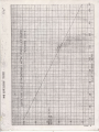
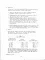
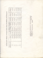
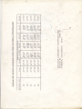
Repairs
Major and minor repairs
only within
the limitations
o f C A D {1 8
are permissible.
In any case, do not exceed the repair limits
for width or thickness as specified
in Table I.
TABLE I
B],ADE REPAIR LIMITS
Blade Station
(Distance from hub
center l ine , in. )
7
11
16
22
27
33
13/32
3/ 3 2
2t/32
L3/64
3/4
19/64
Min imum
R epai red l ^/i dth
5.060
*
Min imum
R epai red Thi ckness
s - :a c ' l
s - s z o*- 5 ' ) s q
s . r + +-o- ' f-. t ( '
F A ' t . / S )
5
.270
4/.55 (
4 . 75 0
3 . 7 4 0 - 3. J>E
2,+ >
1.500 |
,t : J
1 . 1 0 0 i- , C
? ? 7
.7go
'i 1
.604 )
.443 3 ' i /
.294 a l o i
The only aeceptable methods of repairing
cuts, nicks, cracks, etc.,
ar e th o s e b y w h i c h th e d a m aged popti on
i s removed to l eave a smooth
well-faired
surfaee.
Methods which attempt to relocate metal by
c old-w o rk i n g
to e o v e r o r c onceal the defect rather
than remove the
damage are not permissible.
September 26,
L962
-6-
F.
G.
Cheeking Propeller
Track in the Shop
1.
Mount it
on a protractor
2.
Plaee e stationary object
make a mark on the objeet
it.
3.
Rotate the propeller
with this blade.
4.
Measure the distance between the centerlines
The allowable difference is L/8 inch.
5.
If the distance is greater than I/8 inch, the propeller
be sent to an FAA certif icated propell.er repair station
further
inspection and repair.
Checking Propeller
beneh mandrel.
at the tip of one of the blades and
where the eenter of the blade touches
180 degrees and repeat the above operation
of the two marks.
should
for
Track on the Aircraft
The following precedure should not be attempted unless it is
knourn that the engine shaf t is not out of l ine.
The airplane
must be in a hangar where air currents will. not rock it.
Use
the following procedure:
H.
1.
Place a stationary object at the tip of one of the blades
and make a mark on the object where the center of the blade
touches it.
2.
Rotate the propeller
with this blade.
3.
Measure the distance between the eenterlines
The allowable difference is I/8 ineh.
4.
If the distance is greater than L/8 inch, the propeller
should be sent to an FAA certificated
propeller repair
station for further inspection and repair.
180 degrees and repeat the above operation
of the two marks.
Pa int ing
Carefully touch up minor paint damage due to repair operation
or hlear. Propellers requiring complete repainting shal1 f irst be
stripped of their remaining paint and then painted according to
the following instructions :
l.
All surfaces to be painted shall be thoroughly cleaned
innnediately before the application
of the primary coat.
Use benzol, carbon tetrachloride
or some other suitable
organic solvent.
Use same care when applying second topcoat,
that preceding topcoat has not become soiled.
2,
The flat face of the blade will receive a three-coat application;
one Primary coat and two topcoats.
Mask-off the camber face of
the blade, using any suitable method.
September 26, L962
7-
3.
I.
The primer sha1l be zinc chromate thinned with to1uo1.
A pp l y i t e v e n l y o v e r th e surfaee of bl ade avoi di ng
a heavy
c oa t.
A 1 1 o w to d ry fo r at l east 30 mi nutes at room temperature
in a dust free atmosphere.
Balanc ing
Following any appreciable
blade repair,
the propeller
must be
balanc ed .
T h e s u s p e n s i o n ty p e bal ancer
i s recommended beeause
of the direct
indication
of the direction
in which the propeller
is out of balance, to delieately
adjusted balance ways are
necesssry, and because of its ease of interpretation.
s m a11 a m o u n ts o f u n b a l a n c e c an be corrected
by sprayi ng
an
additional
light
coat of black paint on the flat
face of the
light
blade.
Do not use heavy applications
of paint for this
purpose, since unbalance will
re-occur
as soon as the paint erodes
away.
"
A ppr ec ia b l e
u n b a l a n c e c a n b e corrected
onl y by removi ng materi al .
This ean best be accomplished by abrasive grinding
and polishing,
and s ho u l d b e d o n e o n l y o n the camber si de of each bl ade and on the
s ides o f th e h u b .
M e ta l re moved must be hel d w i thi n
the l i sri ts
in
T able I .
S i d e w a y s u n b a l a n c e can often be best corrected
by removal
of m et a l o n th e c a mb e r s i d e c l ose to the l eadi ng edge of one bl ade
and t o th e tra i l i n g
e d g e o f t he other bl ade on the heavy si de.
It is important not to leave any abrasive seratches across the blade.
Always finish
the polishing
operation
so that any abrasive marks that
m ay r em a i n ru n a l o n g th e b l a d es, not across them.
In any case,
remove all deep scratehes.
F or t hose w h o h a v e c o n v e n ti o n a l
bal anci ng
arbors,
adapter cones, and
parallel
knife edges, the proeedure is identical
to the preceding
ins t r uc t io n s .
H o w e v e r, i n s te ad of unbal ance bei ng i ndi cated
by a
disc indicator,
it is indicated
by a tendency of the propeller
to
r ot at e
to w a rd th e h e a v y s i d e .
It shoul d be noted that the kni fe
edges, arbors, and adapters must be free from all foreign matter,
and
m us t be s mo o th a n d tru e .
T h e w ays shoul d be checked for paral l el i sm
prior
to balancing
the propeller.
September 26 , L962
-8-
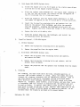
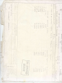
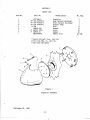
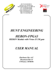
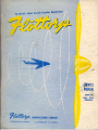
SECTIONV
PARTS LIST
Part No.
I t em N o .
1
2
3
4
5
6
7
#*
#*
#*
@
#
#
:
Nomenclature
FlC7660-2
169-910030-5
169-910030-3
169-910030-1
336
AN960-616
AIit525-10R8
AIit960-10
MS20995C41
No. Req.
Propeller
Rear Spinner Bulkhead
Front Spinner Bulkhead
Spinner Dome
BoIt
Washer
Serew
Washer
Safety Wire
* Beech Aircraft
@ Flottorp
# O p ti o n al
Corp. Part No.
Mfg. Co. Part No.
E qui pment
"Q"
o
I
I
\
l-----,-----./
---'
Figure
Propeller
September 26, 1.962
-9-
1
Assenbly
o
1
1
1
1
6
6
10
10
as req.
s
t
b
F
{
i
}
f
\
.
t
f
i
r
h
F
; .fif' r -qf[ u f f
f*l
.)
h
frt
r{
frt
*f
r{
t"i
tn
r"l
} . . ' ,
s(rl
;
&
$
$ F $ $
; - l $ H H H
n s $ t F F s
$i
h s f r n *
H;
F s g $
HqF
Sfrf--ffift
ilffi
[t],*'
as
b b '
r
H$ $ ' } s p $ $
s'ftfrftffi
Hu
$ h r $ $
I't
,tt
trf
-?"1
:
tlr
: + j
i l q q q f f i
I t $ $ s s
i n .
i d Ii
t
l[*,-".ii
tr't
I \ t \ h . t \
I'l
rrt
rrl
fi$
fififi
{tl1
I
i
f*.
.,-.
r tl-di{.r|r^#d*qr*aftr'H'*,rFrra
I Hl
It Ht
Hi[ \ q f i - H ' $
v
I
t
\-,
-.,
___
-:,'dtl;
'' --'
"'--'-'------.f-'
a
1
}.]
F
4.
.,.
+
,ftJ
l ( )
:
t-{
tl- N3
II
m
o
Y \tjt
F
r
I
I
I
l
T
II
I
l
I
I
I;
.tu
.,-.i;14
J
trl
I H
l a
l3
l e ,
ll zi
l : f
I
II
7.
I
I
;:
I
-[
\
\
.d
7.
I
I
N
l
u
.
i
\
c
J
n-
U
-l
$
E
II
ol
(,
z,
I
L.l
I
l
-7.
t !
tr1
-
N
'u ] [:n
-t
J
rll
:
s
U
z
rd
q
\ll
\
r\
I
I
7.
Ji
U
\^
-i
ii
c0
r!
v
J
q
' f)
{
,
L]
]
Jl
,
O
q
g
lu
*{
:
o
v
r r I
0
J
o
U.
tr
tu
\rl
U
q
u
7 - -
nbl
4 '
o,
i) oh rUo. V
N l r n' s. fr n
1 n
:
t\t
U
)4*z-
z
1.rs3Pf;3
n
(
u
Y
U
\
tfl
O
r - I
-u
g
td
F
,
s(
-
F
U)
l.tl
I
\
z
7.
ft -
V.
H
LJ
U
v.
3
]
0 C \
lit
l-
4
o J
o q ,
t,
;i
F'
.U
:
IF
e
I
t'',t',
,LI
|'rJ
t.t
C J
crJ
F.
H
I
s'L-
h-,
nbbNns
3t
;r,
F
I
td
l r
gi:rlYJs uF'
o o . o g & < o
U)
n
\
.
\J
tt!
gr
a"
o
e9
o
li
b- l ,*r ss ^N ?
n
s
-> a N o I- rfl :.d\
r /o
r r n' tn, Qt lon
I t-$ +
I
trl
rn
o
I z .
;
I
c
ll : h
)
$
J
.J
I,!t
s=
,-q
rt,nnr'
f;
r :H H H H I l F
hi
tr
a"
ia
;
J
/
Y
q
I
I
a f
'
(]
ru
i
*
\ f.-$ \f
r
'
r
t - ' :\
{i
P I
;
A
HH
c o o {'to +
t
I
I
I
l*
tJ-l
vl
T
ri
Y
.\
ULC
I
o
cl
v1
X 9 0 0 6 \ q YN s
II ;
I
z
\o
,4
q
l
-\l
u
(
? '
:#
t{l
t&
,ti
I
t*
U
tll
.&
l
\.v
'
F
[:
; nq&r
E u
I o
'E
l\o,1rill\Om
\ t\ d O
tO \o O tn tl
O N r { l - t O t o ' l
{u,\ri,Jo1'ti
v
8 u
e a
E
o
!t
6
2 p\
?,r
Ld
: , \ R h , , -
O
tq
o
o
a
N
(-l
o
01
O\
N
o
q
H
il-
o
ot
n
q
H
.\Fl
Nt \* d- S" q:
,$kskEi*H*.se
Ln.
N
d
c\l
>
\ _
Y O
ilc\
a
$N
i*l
n_
n
3
| ) .
:\o
i'
'
\
o
a
N
;
\a-
\
-
,
*
&
q\
*t-.
\
\
fo*foil"nr
nrnro
Fr3i e- tt $*
6
("t
qff
N[*
-r\
601
n
c.i
o
Cf
6skF
Qi.^u
cq-{ c\le6 Q eti
al ft
6q
o
O.l
6Ft
o
C\
o
C.l
c.i
c-i
o
o
o
5
6
o
o
o
o
o
N
N
q q t " t o . ) F l
N
N
N
n n q q n " )
il
E
O
E1
H
0{
\
i
'\
a
tc\
.
q 8 G $
ti
i
\
,
/
t
'4'
.
.1' R'9', ::-
".lf
t'
.
:t i \'. ' \ , , : '
-
fw Sb 6=".t* gn
cFl
it
-
Hq
o
f.)
H
.
{-o^
At\
H "i
o
-
sl Fr Rn:
$:
tt
Lu* Q'';.$ oq1- ot6. or€--
Nr..
41
'.,'i
\
$
I
l
'
il
\
o
i
.10\ \
Lc)
o
it
il-
+')J-*
r'"'
qFtJnt
l+r u,
hs
n .-'
\
(\J
\
Rqo
q \ JS H *
q 6
o
U
"
o
o
il ol de
ft
I
d
q
'"*'
b $
Fi
'nn
Rsj
l-i -
]\
<FTE
S Fa,
F
PD
E
<o
5q{
$