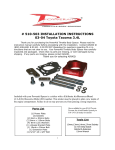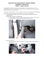
1
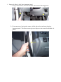
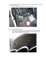
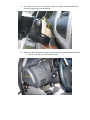
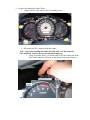
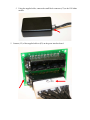
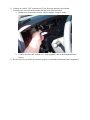
Hypertech Inline Speedometer Calibrator Module
Installation Instructions
730107 - Toyota Tacoma
This installation manual shows an example of an installation on a Toyota Tacoma; however, the
installation may vary for your vehicle, so it may be necessary to consult the Toyota service manual for
specific instructions for your year model.
Tools Needed: 10mm nut driver or socket, #1 Phillips screwdriver, and Trim Removal Tools (Optional)
Be advised: These instructions may not include specifics for all vehicle configurations.
1. Set Parking brake and adjust steering wheel to various settings to facilitate removing the
Instrument panel.
2. Partially remove the driver’s side kick panel.
a. Using your hands, gently pull straight back on the kick panel. There are 2 release clips;
one is shown below. The other clip is directly below the one shown.
3. Remove the coin tray.
a. There are 4 clips that hold the tray in place. Gently pull straight out from the dash to
remove the tray
4. Remove the driver’s side, lower instrument panel.
a. Using a 10mm socket, remove the two bolts shown in the following photos.
b. It’s not necessary, but it makes room to pull the door seal out and away from the
instrument panel. This allows room to get your fingers or trim removal tool behind the
panels.
c. Starting on the lower left-hand side, gently separate the lower instrument panel by pulling
straight out from the dash.
i. When it’s completely separated, lower it to the floorboard.
d. Remove the Instrument Panel bezel.
i. Using a #1 Phillips screwdriver, remove the screws shown in the photo below.
Note: make sure that good contact between the screwdriver and screw is
made to ensure that the head is not stripped.
ii. It is a good idea to place some thick card-stock or paper around the top of the
steering column to prevent scratching.
iii. Starting on the left-hand side, gently separate the upper Instrument Panel Bezel.
1. Rotate it up and to the left and let it hang.
e. Remove the Instrument Panel Cluster
i. Using a 10mm socket, remove the (4) retaining screws.
ii. Disconnect the IPC connector from the cluster.
Note: To prevent breaking the connectors, DO NOT rock the connector
back and forth. Squeeze the release and pull straight up.
1. Using your index finger, you will be able to feel the locking tab on the
back of the connector. Press-in on the tab and remove the connector
f. Using the supplied cable, connect the small black connector (C3) to the VSS inline
module.
5. Connect (C2) of the supplied cable to (P2) on the green interface board.
6. Connect the vehicle’s IPC connector to (P1) of the green interface circuit board.
7. Carefully stow away the inline module and the green interface board.
a. Both pieces can be tied to a brace, cable or support, using tie wraps.
b. Connect the other end, marked (C1), of the supplied cable to the Instrument Panel
Cluster.
8. Reverse the process of this document to properly re-install the Instrument Panel components.