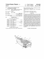
1
United States Patent [19]
[11]
[45]
Zaleslri
[54] APPARATUS FOR TESTING AUTO
ELECTRONICS SYSTEMS
[76] Inventor:
James V. Zaleski, 1631 Paterna Rd.,
Santa Barbara, Calif. 93103
[22] Filed:
Jan.15,11986
111L101.4 ............................................ .. 13061‘ 15/20
11.5. C1. ............................. .. 364/551; 364/431.01;
371/20; 73/116
[58]
1515111 of Search ................. .. 364/551, 550, 431.01;
[56]
371/20; 324/73 R, 73 AT; 73/116, 118.1
References Cited
U.S. PATENT DOCUMENTS
4,107,717 8/1978
4,108,358 8/1978
4,128,005 12/1978
4,200,224
4/1980
4,245.309
1/1981
Klotzner et al. .
Niemaszyk et al. ................ .. 371/20
Arnston et a]. .
Flint .................................... .. 371/20
Kiefer
. . . . .. . . . . . . . .
4,694,408
Sep. 15, 1987
Faults Automatically", by R. A. Anderson et a1, Elec
tronics, pp. 1ll—-117, May 1978.
“The Revolution in Diagnosis is Now”, OTC publica
tions.
Primary Examiner—Parshotam S. Lall
Attorney, Agent. or Firm-Koppel & Harris
[21] Appl.No.: 019,252
[51]
‘ [52]
Patent Number:
Date of Patent:
. . . . ..
[57]
ABSTRACT
An interactive system and method for testing vehicle
electronics systems is disclosed in which various vehicle
subsystems are exercised under the control of the tester
unit while the performance of associated subsystems are
monitored to detect and isolate malfunctions. The tester
includes interchangeable program cartridges that can be
easily inserted to adapt the unit for a variety of different
vehicles and test procedures, and also optional inter
changeable input/output cartridges for test procedures
in which additional access to or from the tester or pe
ripheral devices is necessary. The test unit accesses the
371/20
4,267,569
5/1981
Baumanri et al. ............ .. 364/431.01
4,271,402
6/1981
Kastura et al. .
4,380,070
4/1983
Steiner ................................ .. 371/20
4,404,639 9/1983
4,442,424 4/1984
4,476,531 10/1984
4,497,057 l/l985
McGuire et al. .
Shirasaki et al. .
Marino et al. ................ .. 364/4310]
Kato et a1. 1
OTHER PUBLICATIONS
“Processor-Based Tester Goes on Site to Isolate Board
vehicle’s electronics data bus by means of an assembly
line diagnostic link, the access being accomplished via a
multiplexer that makes it possible to locate faults on the
data bus itself. The tester greatly reduces the time and
effort necessary to analyze malfunctions in the ?eld, and
is considerably more comprehensive than prior test
equipment.
13 Claims, 16 Drawing Figures
m<
Patent
Sep. 459 4987
1
P
r
l/
“7
Sheet 1 of M
4,694,408
C
@
atent
Sep. 159 R987
sheew 0m
4,694,408
1 ; 1‘
atent
Sep. M91987
sham 0m
4,694,408
ML47
111
/wmnmnm
K48
MSW Patent Sep. 1591987
n w=_ _ = _
mm“wmwmwm
Sheet 4 of M
. ____
4,694,408
Patent Sep. T59 T987
4,694,408
Sheet 6 of M
ZOI
202
gssus
SWITCH TESTER
FROM SLAVE TO
MASTER
MODE
'DOWNLOAD
REQUEST"
MESSAGE TO
i
am
@209
DOWNLOAD
203
ALDL
INITIATE
DOWNLOAD
MESSAGE
"OUTCONTROL" ROUTINE
mo
5cm
SCRATCHPAD
RAM
2
oowmoao
i204
DOWNLOAD
" BOOTLOAD
MESgAGE
ROUTINE m
ECM Rm
f ‘2H
205
AND "ouTcoNTRoL"
ROUTINE IN BCM ( SLAVE)
MESéAGE
"ExEcuTE
DOWNLOAD"
MESSAGE
INITIATE PERIODIC
commumcmow BETWEEN
TESTER (MASTER)
ALDL
INTER ROGATION
ISSUE
210
ALDI.
SUCCES§ UL
. 5206
GO TO
SUBSYSTEM
EMULATTON
ROUTlNE
Z?igJLa.
Sheet 7.01‘ R l
W
4,694,408
BOOTLOAD
START
INIT. OUTPUT
COMPARE AND TIMEOUT
n25
TIMERS
)NITIALIZE SERIAL
$214
COMMUNICATION
PORT AND VMRIABLES
SERIAL
0AM
acv‘o
‘
‘
215
216
UPDATE CHECK SUM
92]?
UPDATE EYTE COUNTER
S‘WE D?hTA
YEW»
224
MESSAGE
“
COMPLETE
‘
“‘
JUMP TO
DOWNLOADED ROUTINE
TOGGLE cop
220
oecneuem'
+
TIME-OUT
'rmaw
ZZI
J
TIMEOUT
223
JUMP TO
RESET VECTOR
SheetS 0m
4,694,408
OUTCNTRL
sun-r
r5225
lNlT. OUTPU?
COMPARE AND LOSS OF
g?igolloro
COMM. TIME-IRS
4
TRANSMIT " oowmoao
J 226
mmmomzoea "' use»
227
CHECK TIMERS AND
V
PERIODICALLY TOGGLE COP
COMMUNICATION
YES
B E E N LOST
228
JUMP TO
RESET VECTOR
SERIAL I
DATA RCV D
PROCESS
RECEIVED
0mm
'9 23'
234
PROCESS new 0 use.
0
DISCRETE OUTPUT
0
SLEW OUTPUT
Q Ma CONVERSION
a
CLEAR LOSS 0F
COMMUNICATlON' TlMER
‘I
GUI?
IDLE
TRANSMIT " COMMAND
ACKNOWLEDGE" MSG
l_~'
l (235
SepQ 1591987
33K
Sheet W of M 4,694,408
zo m
atent Sep. 15,1987
Sheet M 0m 4,694,408
[__'—'_'_——__—_________—__"1
£150
, *DI
4
'
"ll-I42
96cc aAuo
‘
GENERATOR —0/5_
I
J3
LNG
I441
RAM
>TIME OF
32'‘ x 8
DAY CLOCK
‘)3
138
9600 __ I
SWlTCH - I
EXTERNAL
|
I
LH E “J (VSM)
———>
BATTERY
POWER
mu.
5T BY
P/S
-
<-
I
|
r __.._|
I
‘
lLwe
‘r:
II
I34
swrrcn
I
CARTRIDGE
wvoc
3%13»?
else/g
1
I30
1
W
l
l
ACTWITY
MONITOR
l
TO ALDL
POWER
CABLE
ll
4,694,408
APPARATUS FOR TESTllNG AUTO ELECTRONICS
SYSTEMS
BACKGROUND OF THE INVENTON
1. Field of the Invention
This invention relates to automobile testing equip
ment and methods, and more particularly to the diag
nostic testing of automobile electronics systems.
2. Description of the Prior Art
As the use of electronics to control and perform vari
2
motive problems are intermittent and do not show up in
a single test run. Current testers do not have the capabil
ity of monitoring a vehicle‘s performance over a long
period of time and capturing the status of the various
electronics systems when an intermittent malfunction
occurs so as to enable effective diagnostic analysis.
SUMMARY OF THE INVENTION
In view of the above problems associated with the
prior art, it is an object of the present invention to pro
tive electronics systems has grown to be more of a
vide a novel and improved testing unit and method for
automotive electronics systems which provides for both
passive monitoring of the various systems, and for the
active exercising and control of a particular system and
problem. (The term “automobile’” as used herein in
cludes trucks and other vehicles having electronics
systems analogous to those found in automobiles.) Cur
systems to identify any malfunctions related to the sys
tem being tested.
ous automotive functions becomes more prevalent. the
quick, accurate and comprehensive testing of automo
the simultaneous monitoring of associated electronics
rently available ?eld test equipment is generally passive
Another object is the provision of such a testing unit
in nature. The testers monitor the outputs of various
in a compact, portable package that can be hand held
electronics systems in the automobile for a given oper 20 and either kept at a local testing site or allowed to travel
ating condition, such as the motor idling, in an attempt
with the vehicle.
to determine the cause of a malfunction. However, it
Still another object is the provision of a novel and
'may not be possible to determine the cause of many
improved automotive electronics tester which can be
malfunctions without taking the automobile through a
easily and inexpensively adapted for use with many
sequence of operating conditions, such as starting the 25 different kinds of automobiles having a wide variety of
engine and accelerating to a high speed, and simulta
electronic data formats.
neously observing the condition of the electronics sys
tems during the testing sequence. Available testers do
not have any convenient mechanism for sequencing an
automobile through a variety of operating conditions,
and are generally limited in the number of different
responses they can observe.
The inability to perform comprehensive diagnostic
A further object is the provision of such a testing unit
and associated method for continuously monitoring an
automobile during normal use and for activating the
unit upon the occurrence of an intermittent malfunction
to locate and diagnose the problem.
These and other objects are accomplished in the pres
ent invention by means of a diagnostic test unit which
testing of electronics systems at the local site level can
result in great inef?ciencies. For example, it is often 35 includes a microprocessor that both controls an active
dif?cult to determine whether a particular problem
resides in the engine or the transmission. Of transmis
sions which are shipped back to the factory for correc
tion, the majority are returned with no problem having
been located, while in most of the remainder the prob
lem is corrected by a minor adjustment at the factory
that could have been made in the ?eld had the proper
diagnostic equipment been available.
Another complicating factor in electronics testing is
test sequence applied to speci?ed electronics systems in
the automobile and monitors the responses of associated
systems; a means such as a keyboard for providing oper
ational controls to the microprocessor; a display for
operator real time readout of test results; a program
means for providing diagnostic test sequences to the
microprocessor; a transceiver which provides a two
way interface between the microprocessor and the au
tomobile electronics systems to transmit test signals
the proliferation of many different electronics systems 45 from the microprocessor for exercising particular sys
tems in the automobile, and to enable the microproces
for different makes of cars, among different models
from the same automotive manufacturer, and even an
sor to monitor the condition of associated systems while
nual changes within the same model line. The different
the ?rst system is being exercised; and a power supply
electronics systems are generally accompanied by dif
ferent data formats that limit any particular testing unit‘
to only a relatively small number of vehicles. Stocking
a large number of different monitors to accommodate
the various makes and models is expensive, inef?cient
and wasteful. However, due to the complexity of cur
rent electronics systems, it is dif?cult and sometimes 55
impossible to perform adequate ?eld service without
the use of proper electronic testers.
for the unit. The tester is adapted to receive a number of
interchangeable program cartridges, each cartridge
providing desired test sequences for particular makes,
models and years. In this way the ?eld test site need
only inventory a collection of small and relatively inex
pensive cartridges, each of which can be inserted into a
single testing unit as needed.
'
The automobile’s internal electronics data bus to
which many of its electronics systems are connected is
accessed by connecting the tester to an associated as
The proliferation of different electronics systems is
sembly line diagnostic link (ALDL). For automobiles in
not limited to different makes and models; often the
same model car will employ signi?cantly different data 60 which the electronics data bus is provided as a ring bus
formats with each successive model year. This rapidly
obsoletes testers which are dedicated to any particular
make or model.
with a pair of output terminals, the tester is connected
to both terminals and provided with a multiplexer
which multiplexes test patterns onto both terminals.
Each of the automobile systems on the data bus can thus
Another problem is the dif?culty in simulating nor
mal driving conditions within the con?nes of an auto 65 continue to be accessed despite the presence of a fault
on the bus, and the location of the fault can be found by
motive repair shop, while at the same time monitoring
the various electronics systems to determine the loca
determining the penetration of each multiplexed con
nection.
tion and nature of any malfunctions. Also, some auto
3
4,694,408
cartridges, the tester is also adapted to receive a number
of different input/output cartridges. These latter car
tridges are used for tests which require accessing the
automotive electronics both through the assembly line
diagnostic link and also at various special test points not
on the assembly line data link, or for interfacing with
testing is performed in a pre-programmed sequence, as
explained further below, but manual overrides and op
erational controls can be input through the keyboard.
peripheral equipment. An input/output cartridge can
also be provided for communicating the test results to a
remote location, such as a central diagnostic center.
In addition, the tester can be used as a portable vehi
cle data monitor to detect intermittent malfunctions
during normal driving. Connected to the data bus in a
An alphanumeric liquid crystal display 10 provides
information on the testing results; the particular infor
mation to be displayed can also be controlled through
the keyboard 4.
low power standby mode, the tester ‘*wakes" itself up
when it senses data bus activity, and then monitors the
activity on the data bus to capture the status of the
various electronics systems in memory at the moment a
4
conducted, but in general the keys can be used to vary
the automotive condition so that the operation of the
car’s electronics systems can be monitored under differ
ent conditions. For example, for testing with the motor
running, the “accelerate” button 6 can be depressed to
speed up the engine, while the "decelerate” button 8
can be depressed to slow the engine down. In general,
In a manner similar to the interchangeable memory
5
malfunction occurs.
These and other features and advantages of the inven
tion will be apparent to those skilled in the art from the
following detailed description of preferred embodi
ments, taken together with the accompanying draw
ings, in which:
The tester includes built-in software routines that are
independent of any particular testing application, and
are useful in a variety of different applications. The
built-in routines fall into four categories: executive rou
tines; serial data handling routines; self-test routines;
and general utility routines.
In addition to the built-in software, the tester housing
includes a receptacle for interchangeable plug-in pro
gram cartridges 12. Each cartridge is programmed to
run one or more particular test sequences for a particu
DESCRIPTION OF THE DRAWINGS
25 lar automotive model or series of models. After a test
sequence has been completed, the cartridge may simply
FIG. 1 is a perspective view of a portable automobile
be removed and replaced with a different cartridge,
electronics testing unit constructed in accordance with
thereby making it possible to perform different tests on
the invention;
different types of cars having very different electronics
FIG. 2 is a sectional view taken along the lines 2-2
systems with a single tester and an inventory of inexpen»
of FIG. 1;
sive program cartridges. Some examples of the different
FIG. 3 is a plan sectional view of a program cartridge
types of cartridges that can be provided are:
used in connection with the tester;
FIG. 4 is a sectional view taken along the line 4—4 of
FIG. 3;
FIGS. 5, 6 and 7 are respectively plan, fronta'l eleva
tional and side elevational views of an input/output
cartridge used in connection with the tester;
FIGS. 8 and 9 are respectively plan and side eleva
tional views of another input/output cartridge used as a
communications interface for the tester;
FIG. 10 is a block diagram showing the connection of
the tester to an automobile electronics data bus;
FIGS. 11a, 11b and He are collectively a flow dia
gram of the program applied to the automobile’s body
computer module to emulate the operation of various 45
automotive systems and thereby effectively decouple
the master controller from the electronic data bus dur
ing testing;
FIG. 12 is a block diagram of the electronic compo
nents employed in the tester;
FIG. 13 is a schematic diagram of the circuitry used
in the transceiver and multiplexer portions of the tester;
and
FIG. 14 is a block diagram of an input/output car
tridge used to monitor the automobile electronics for
intermittent malfunctions.
DETAILED DESCRIPTION OF PREFERRED
EMBODIMENTS
A perspective view of the hand held automotive
Engine Control Module Testing Cartridge
This test program is similar to conventional passive
testing, in which data is obtained from the vehicle’s
engine control module (ECM), including ECM mal
function codes as well as diagnostic data. The data
streams are captured on a scheduled or event-triggered
basis, scaled, and displayed in pre-selected or operator
selected pairs. Various readout modes can be selected
by the operator.
System Diagnostic Testing Cartridge
The diagnostic test cartridge has three capabilities:
subsystem testing, vehicle service diagnostics, and inter
mittent or “snapshot” testing. The subsystem testing
provides the ability to monitor and control all serial
data coming from or going to any speci?ed automotive
electronics subsystem. This allows the technician to
decouple the subsystem from the normal master
directed operation and exercise it independently of all
other subsystems. The subsystem tests include:
(I) BCM. A passive monitoring of all normal commu
nications transmitted from or received by the master
controller, or body computer module (BCM), including
data to and from the engine control module (ECM),
instrument panel cluster (IPC), heating, ventilation and
air conditioning unit (HVAC) and secondary displays.
given in FIG. 1. The tester is contained in a housing 2 ‘
(2) ECM. In the ECM tests the technician can either
monitor ECM serial data, or control certain ECM dis
crete outputs. The output control function allows the
that is very convenient to handle, weighing less than 3
technician to control such outputs as the torque con
electronics tester provided by the present invention is
verter clutch, the canister purge solenoid or the idle air
pounds and approximately 8 inches long, 3.7 inches
wide and 1.875 inches deep. A 16 key, multi-function 65 control motor.
keyboard 4 with tactile feel provides program instruc
(3) IPC. Such IPC operational data as the fuel gauge
tions to the internal tester electronics. The functions of
or IPC switch closures can be monitored. The tester can
the various keys depends upon the particular tests being
also assume control of the serial data bus and emulate
5
4,694,408
the BCM relative to its control of the IPC to determine
whether or not a problem is in the IPC. For example,
6
with the same type of information as the functional test
director for the selected subsytem.
The functional test director is an example of one
application of the basic tester.
IPC displays can be controlled, display segments tested,
and telltails turned on and off.
(4) HVAC. As with the previous tests, the HVAC
test provides the technician with the capability of moni
toring normal communications with the HVAC. In the
control tests, all of the discrete output commands of the
Communications Interface Cartridge
This program cartridge provides a standard RS232C
interface for the tester which allows the tester to be
HVAC can be controlled such as positioning the air
interfaced with printers, modems, full function key
flow doors, engaging/disengaging A/C clutch, and
controlling the blower motor speed.
boards or remote host computers. The cartridge in
cludes a 16 K byte EPROM which controls software
(5) Secondary Display. With this cartridge the tester
that allows for a remote keyboard operation bypassing
the tester keyboard 4 for user-de?ned key commands;
remote display of the tester display parameters; trans
can monitor data transmitted to or from each of the
displays, as well as control a portion of the function
which the devices can display, such as driving individ
mission of remote host-selected parameters; and trans
mission of raw, unprocessed vehicle data. With this
ual displays or performing display segment tests.
cartridge an auto can be tested from a remote location
where better facilities or more trained personnel may be
With the vehicle service diagnostic test, the tester is
capable of performing almost all of the functions per
located.
The cartridge can also be used to debug tester soft
ware during development via a CRT/keyboard or per
formed by the vehicles’ on-board service diagnostics,
including displaying ECM and BCM malfunction
codes, monitoring assembly line diagnostic link
(ALDL) discrete and analog parameters, and control
ling ECM and BCM outputs. This cartridge also pro
sonal computer by the use of routines such as the Mo
torola “LILbug" debug routine.
Additional Program Cartridges
vides a number of enhancements over the on-board
service diagnostics.
Further program cartridges which may be inserted
For intermittent testing, the cartridge enables the
_into the tester include ones for transmission diagnostics,
tester to monitor various subsytems and capture a
remote radio/control head diagnostics, digital volt
ohmmeter, vibration analyzer, multiplex system exer
“snapshot” of the serial data under certain conditions.
These conditions can include the occurrence of a speci 30
ciser and others. Also, different cartridges may have to
?ed ECM or BCM malfunction code, the occurrence of
any ECM or BCM malfunction code, the occurrence of
any malfunction code, or a manual trigger via the tester
keyboard 4. Once the intermittent test trigger has oc
be provided to perform the same types of tests on differ
ent models or even for different annual versions of the
same model.
Continuing with the description of the basic tester
shown in FIG. l, a plug-in connector 14 is inserted into
a multiprong input/ output socket on the tester and held
in place by means of screws on either side of the con
curred, the program cartridge enables the technician to
select between displaying up to 64 samples of ALDL
data before and after the trigger, including malfunction
codes, or displaying the normal communication data.
nector. A cable 116 extends from the connector and is
The tester can be left in place on the vehicle during
provided at its opposite end with another connector
normal operation away from the ?eld service center,
with the intermittent test mode used to capture the
(not shown) that connects to the vehicle’s electronic
data bus via the ALDL. This is the basic communica
subsystem conditions upon the occurrence of a particu
lar intermittent malfunction and thus diagnose the mal
function.
tions link by which the condition of the various automo
bile systems are monitored by the tester, and active
Functional Test Director Cartridge
This program cartridge contains a functional test
45
signals applied from the tester to exercise selected vehi
cle systems. Power is also supplied from the vehicle
cigarette lighter socket via cable 16 to the tester.
In addition to the basic connection between the tester
director that automatically executes a series of engine
control tests interactively with the service technician.
The functional test director provides the service techni
cian with subsystem-level fault isolation, such as the O3
tester to both the ALDL and a second location on the
vehicle, or it may be desired to connect the tester to
sensor circuit, fan circuit, etc., by exercising particular
subsystems in turn and concurrently monitoring the
printer. For this purpose, a second receptacle is pro
and vehicle via connector 14 and cable 16, certain addi
tional tests may be accomplished by connecting the
peripheral input/output devices such as a modem or
condition of associated subsystems. When a particular
vided in the tester for a removeable input/output car
fault has been isolated, the functional test director stops 55 tridge 18 that provides the second connection to the
executing and notifies the technician of the problem
vehicle or peripheral device. Examples of test functions
area, as well as a key into the vehicle‘s service manual to
that would require both the ALDL connector and a
be used to solve the problem. Various subsystems or
separate input/output cartridge include hydramatic
engine problems which may be included as part of the
power train and air conditioner diagnostic testing.
fault isolation are: throttle position sensor; reference
The internal mechanical structure of the tester is
pulse sensor circuit; park/neutral switch circuit; mani'
shown in FIG. 2. The internal electronics are mounted
on a main circuit board 20, including a transformer 22
fold air pressure (MAP) sensor; idle arm control (IAC)
used to supply the tester with power from the vehicle.
motor; oxygen sensor; system rich/lean; fan circuit;
thermostat.
A program cartridge 12 is shown in place, with its elec
This program cartridge also allows a subset of the 65 tronies mounted on a circuit board 24 and connected to
engine control tests executed by the functional test
the tester electronics via an edge board connector 26.
An input/output cartridge 18 with its electronics ac
director to be executed on an individual basis by the
quires data from its associated cable 28 and provides it
technician. The individual tests provide the technician
7
4,694,408
8
ware. An eight position switch 59 allows the RS232
to the tester electronics via an edge board connector 30.
A ?at cable 31 connects the program cartridge 12 and
data rate to be varied from 160 up to 19,200 BAUD.
input/output cartridge 18 to the microprocessor bus on
the main circuit card 20 via connector 32. Cable 16 is a
For other applications requiring a separate input/out
put cartridge, such as hydramatic power train, digital
12 lead cable which extends from the tester to an
ALDL connector 33. In addition to providing a con
volt meter and air conditioner diagnostics, an input/out
put cartridge similar in physical construction to the
program cartridge shown in FIGS. 3 and 4 is inserted
nection to the vehicle ALDL, connector 33 ties two of
the cable 16 leads to a two-wire coiled cable 34 that
into the tester‘s input/output receptacle, with the
connects to a cigarette lighter adapter 35. Adaptor 35
ALDL connector 14 left in place.
The manner in which the tester is connected via the
0
plugs into the vehicle‘s cigarette lighter to provide
power to the tester via cable 35, ALDL connector 32
and cable 16.
Referring now to FIGS. 3 and 4, the principal me
chanical features of the program cartridges are shown.
Each cartridge is provided with spring-biased squeez
able latches 36 on each side that can be squeezed in
wardly by means of ?nger pads 38 acting against coil
springs 40, permitting the cartridge to be inserted into
the receptacle in the tester body 2. The spring-biased
latches are then released, latching the cartridge into
place in the receptacle. The cartridge is easily'removed
when desired by simply pressing in on ?nger pads 38 to
release the latch and pulling the cartridge out. To en
sure proper placement in the tester, the top of the car
tridge is provided with a bracket 42 that includes a slot
44 which receives a corresponding locator tab extend
ing in from the tester.
A special input/output cartridge which provides for
a connection with both the tester ALDL ports and the
input/output receptacle is shown in FIGS. 5, 6 and 7.
This auxiliary cartridge 45 provides the low power
standby vehicle data monitor “snapshot” capability
ALDL connector to a vehicle’s electronics data bus is
illustrated in FIGv 10. The electronics data bus 58 inter
connects various vehicle electronics subsystems, such as
BCM 60; ECM 62; HVAC 64; IPC instrument panel 66;
a secondary display subsystem 68 consisting of a CRT
controller (CRTC), an electronic climate control panel
(ECCP) or a climate control and diagnostic information
center (CCDIC); and a voice module 70.
The vehicle‘s ALDL 72 is connected onto the elec
tronics data bus 58 for ?nal assembly line testing at the
factory. It connects to two terminals 74, 76 on the data
bus. This type of bus, in which the two terminals form
a loop with the various subsystems, is referred to as a
“ring‘” bus.
Prior ?eld electronics testing was generally limited to
a passive readout of the ECM by means of a diagnostic
uni-directional serial data line sourced by the ECM and
brought out to the ALDL connector. In the present
invention, by contrast, the tester 2 is connected to the
electronics bi-directional operational data bus 58 by
means of the ALDL 72. This is believed to be a unique
use of the data bus, which was not designed primarily
for diagnostics as was the ECM diagnostic serial data
referred to previously. Its forward end includes a pair of
line. The present tester in essence becomes an integral
latches 46 and ?nger pads 47 on either side which re 35 part of the electronics operational system by connecting
leasably connect the cartridge to the tester input/output
onto the data bus. This novel use of the data bus opens
receptacle. An edge board connector 48 makes electri
up many possibilities for diagnostic testing that could
cal contact with the tester within the receptacle. The
not be performed previously. The tester can be used to
upper portion of this specialty input/output cartridge 45
emulate or exercise any of the vehicle’s subsystems
includes a female socket 49 which plugs into the corre
which are connected to the data bus, while monitoring
sponding pin socket on the tester in place of ALDL
the other sub-systems to detect and identify any mal
connector 14, with the ALDL connector reconnected
functions. The ALDL is not believed to have been
to a corresponding female connector 50 on the rear of
previously used for this type of ?eld testing, and in
cartridge 45. This interception of the ALDL cable is
factory testing it is believed to have been used only as a
used to provide serial link activity monitoring and 45 one-way communications link to read out data from the
power moding control. In addition, a separate cable is
BCM; the ECM is generally accessed in the factory
attached to the cartridge at connector 51 to provide the
either through the ALDL or directly through the
operator trigger control/indicator operations.
ECM.
Another input/output cartridge which houses stan
Applicant’s novel approach provides a substantial
dard RS232 communications interface electronics ap
advantage in the testing of modern electronics systems,
pears in FIGS. 8 and 9. This cartridge 18 is similar in
in that many vehicle functions utilize a number of differ
outward construction to the program cartridge 12, and
ent electronic subsystems. For example, operating the
includes a pair of spring-biased squeezable latches 52 on
air conditioning involves ?ve subsystems: ECM 62,
each side that can be squeezed inwardly by ?nger pads
HVAC 64, IPC 66, ECCP 68 and BCM 60. The identi?
53, permitting the cartridge to be inserted and releas
cation of the particular subsystem responsible for an air
ably latched in the tester’s input/output receptacle. The
conditioner malfunction can be very dif?cult with con
bottom of the cartridge is provided with a bracket 54
ventional testing methods. The present invention ena
that includes a slot 55 which receives a corresponding
bles each of the subsystems in turn to be exercised while
locator tab extending in from the tester to ensure proper
the data bus 58 is monitored to quickly and easily deter
placement. An edge board connector 56 at one end of 60 mine the location and nature of the problem.
the cartridge makes electrical contact with the tester
For the tester to gain full control of the electronics
within the input/output receptacle, while a multipin
socket 57 at its other end receives a communications
data bus 58, the BCM 60 must be effectively decoupled
from the bus. However, simply disconnecting the BCM
cable. A switch 58 is provided to switch the cartridge
from the data bus will result in the shutdown of the total
between an M mode in which data is sent to a peripheral 65 system operation. Applicant has arrived at the novel
solution of using his program cartridges to load a spe
device such as a modem, printer, etc., and at test mode
cial program into the BCM which keeps it functioning
in which the RS232 cartridge is connected to an exter
in a slave state but allows the tester to take over control
nal computer for developing and debugging test soft
9
4,694,408
and emulate the other subsystems on the data bus. This
technique is employed for the various testing applica
tions which use the BCM. Operating as the master, the
tester can emulate any subsystem by sourcing subsystem
messages and transmitting them to the other subsys
tems. The tester can also read data from any subsystem
or control the subsystem by sending control data to it.
A flow diagram of the program which is loaded into
the BCM is provided in FIGS. 1lla-llc. Referring ?rst
10
sages from the tester, which operates as the master. The
tester can command the BCM to set its output discretes
high or low, to slew its analog outputs, or to read its
analog inputs. It can also command the BCM to go idle,
or tell it to quit operating as a slave and return to its
normal operating mode. When executing this routine,
the BCM also checks for valid bus activity and will
revert back to the normal operating mode if it does not
detect proper activity. The operation of OUTCN
to FIG. 110, the BCM emulation starts with the tester O TROL is shown in FIG. Me in which it first initializes
executing an External Load (EXTLD) routine which
Output compare timer and loss of communication tim
?rst downloads a BOOTLOAD routine from the tester
to the BCM RAM memory; loads a second routine,
ers 225 and then transmits a “Download Acknowledge"
message 226 to the tester. It continually checks the
Outcontrol (OUTCNTRL), into the BCM; and then
timers and periodically toggles the COP 227, and
jumps to execute the desired subsystem control or emu
lation routine. The tester waits for an ALDL interroga
tion message 201 from the BCM. It issues a “Download
228. If communication has been lost, the routine jumps
Request“ message 202 to the BCM and waits for a re
sponse 203 from the BCM indicating that it is ready for
checks to see if communication has been lost at any time
to a reset condition 229 and starts operating as a normal
BCM. If communication is normal, it checks 230 and
processes 231 received data, and checks messages for
validity 232 in a manner similar to the BOOTLOAD
routine. When a valid message is received the routine
the download routine. The tester then downloads the
BOOTLOAD routine 204 into the BCM RAM over the
system bus and waits for an ALDL interrogation mes
sage 205 from the BCM. The tester then issues an “Exe
processes the message and responds to its command
233, clears the communication loss timer 234, and trans
cute Download” message 206 to the BCM over the
mits a “Command Acknowledge" message 235 to the
tester. This sequence continues until the tester sends a
system bus, delays 100 msec 207, switches the tester
"Quit" command, at which time the BCM reverts back
from the slave mode to the master mode 208, and down
to its normal operation as system bus master.
loads an OUTCNTRL routine 209 into the BCM
Returning to FIG. 10, the tester makes a pair of sepa
scratchpad RAM via the system bus. When a successful
rate connections to the ALDL through leads ALDL M
download message 210 is received from the BCM, the
tester initiates periodic communication to the 30 and ALDL L. The test signals which are applied from
the tester to the data bus are multiplexed onto these two
OUTCNTRL routine 211 executing in the BCM and
leads such that they alternate between the two leads or
then jumps to the desired subsystem emulation or con
trol routine 212.
are delivered to both simultaneously. This technique is
The BOOTLOAD routine which is loaded into the
BCM from the tester puts the BCM into the slave mode
any faults which may develop on the data bus. For
waiting for messages from the tester. If a message is not
received within a pre-speci?ed time, the BCM reverts
back to the master mode. The function of this routine is
to accept data messages from the tester and store them
in scratchpad RAM. The sum of these messages consti 40
tute an executable routine called OUTCNTRL to
very useful in determining the presence and location of
example, assume that a fault appears on the data bus at
location 78 between the HVAC 64 and IPC 66. The
tester can be programmed to determine that signals on
ALDL L penetrate only to HVAC 64, while signals on
ALDL M penetrate only to IPC 66, or conversely that
only signals from ECM 62 and HVAC 64 are delivered
which the BCM jumps and executes upon successful
to ALDL L and only signals from the remaining subsys
completion of storing all of the routine in RAM.
tems are delivered to ALDL M. The location of the
data bus fault can thus be readily determined. In addi
The execution of BOOTLOAD is shown in FIG. 11b
in which first output compare timers, time-out timers 45 tion, connection through the ALDL makes it possible
to access all of the connected systems and continue
213, and serial communication port/variables 214 are
normal testing despite the presence of a fault on the data
initialized. The BCM monitors the system bus for data
bus.
215 and, if no data is received, it checks to see if it is
A block diagram of the tester is provided in FIG. 12.
time to toggle a Computer Operate (COP) timer 219. If
The main circuit card assembly includes the micro
the toggle time has not arrived, the BCM returns to
processor 80, which in the preferred embodiment is
monitor for serial data received 215. If it is time to
based on the Motorola CMOS 6303. The main circuit
toggle the COP, the COP is toggled 220 to prevent the
board assembly 82 is a two-layer printed wiring board
BCM from automatically resetting. The time-out timer
is decremented 221 and then checked to see if the time
since the last received valid message has exceeded the
time limit 222 and, if it has. the BCM jumps to the reset
vector 223 where the BCM is reset and assumes normal
operation, including control of the system bus. If serial
data has been received 215 it is checked for validity 216
and, if it is not valid, it is ignored and the serial data
ports and variables are reinitialized 214. If the data is
valid it is saved, and a message sumcheck and byte
counter are updated 217. The message is then checked
with dual-in-line package ICs, chip capacitors and resis
tors. In addition to the microprocessor, the main circuit
board contains a 4 MHZ clock oscillator 84, a 64 K
on-board ultraviolet EPROM 86, a 64 K scratch pad
CMOS RAM 88, the keyboard 4 and keyboard encoder
89, an ECM interface 90, an 8192 BAUD (bits per sec
ond) serial data link transceiver 92 whose impedance is
substantially matched with that of the vehicle electron
ics data bus, a multiplexer circuit 94 connected to the
transceiver, and an internal power supply circuit 96
which conditions power from the vehicle data bus for
jumps to the loaded OUTCNTRL routine and starts 65 use by the tester. It is preferably a switching power
supply which provides full operation over 5.1 to 24
executing 224.
for completion 218 and, if it is complete, the BCM
The OUTCNTRL routine causes the BCM to act as
a slave subsystem which receives and processes mes
VDC input voltage with transient and reverse polarity
protection. EPROM 86 constitutes the built~in software
11
4,694,408
12
routines which provide timing sequences and interrupts,
tive of an intermittent malfunction. When a malfunction
processes and decodes the keyboard, places data on
display, controls communications with the vehicle data
condition is detected, the cartridge stores both the sta
tus of the systems being monitored and the time at
which the reading is taken in memory.
A connection is made to the ALDL/power cable via
terminal 124 such that the cartridge data bus 126 carries
bus and provides basic utility packages and tester self
test routines.
The display 10 is provided on a separate circuit board
and is connected to the microprocessor bus via the
the same signal as the vehicle electronics data bus. The
display drivers 100. The ALDL receptacle J1 provides
an interconnection between the ALDL/power supply
activity monitor circuit 128 monitors the data bus 126
and activates a relay 130 when the data bus becomes
active indicating that the vehicle is running. The closing
96. The internal microprocessor bus is brought out on a
wire harness that terminates at 40 pin connectors in the
of relay 130 completes a circuit between the tester via
terminal 132 and the vehicle power via terminal 124 to
provide operating power to the tester. Vehicle power is
program cartridge receptacle J2 and the input/output
cartridge receptacle J3. The program cartridge is
shown with a 256 K EPROM 102 and the I/O cartridge
with a 128 K EPROM 104 which provide appropriate
controls to the microprocessor. The input/output car
tridge is also shown as including an RS232 communica
tions interface 106 which, among other things, can be
brought into the cartridge via terminal 124 and is ap
5 plied to a standby power circuit 134 to power the car
used to test the car from a remote location via commu
nications line 108.
A schematic diagram of the transceiver 92 and multi
plexer 94 sections of the tester circuitry is given in FIG.
13. The multiplexer section is shown to the right of
dashed line 110, and the transceiver section to the left.
tridge RAM 138, a time of day clock 144, and the activ
ity monitor 128. It is also brought to the tester main
power relay 130. Upon closing of the power relay, the
tester becomes active and monitors the data it receives
on line 126 for malfunction conditions. When a ma]
function is detected. the tester logs the data into a 256 K
RAM 138, via line 140 and terminal 142, along with the
value of the time of day clock 144 to log the time at
which the malfunction occurred. A battery 136 is pro
mitted through the transceiver via an invertor INVI
and voltage divider 114 to the gate of a ?eld effect
vided to keep power on the volatile RAM 138 when the
tester is disconnected from the vehicle. A timing circuit
146 provides a bit rate of either 9600 or 8192 bits per
second, depending upon the internal vehicle bit rate, to
transistor FETl which is protected by a ?lter capacitor
junction 142. A manual button input circuit 148 is also
C1. The source of FETl is connected to ground
provided so that data can be stored whenever desired,
and an indicator light driver circuit 150 can also be
Signals to be transmitted to the ALDL connector are
received from the microprocessor on line 112 and trans
through resistor R1, while the signal to be transmitted
to the ALDL is delivered to the multiplexer over lines
provided to turn on a light indicating that the cartridge
116 and 118. Signals received by the multiplexer for
has captured data.
A novel vehicle testing system and method has thus
been described which has four different levels of diag
nostic testing. First, it provides monitoring and control
of individual vehicle subsystems for malfunction isola
tion supported by the technician’s intuitive input. Sec
transmission back to the microprocessor enter the trans
ceiver over line 120, from whence they are delivered to
the inverting input of an operational ampli?er 122. The
inverting and non-inverting inputs of OP amp 122 are
connected to ground through capacitors C2 and C3,
respectively, while the ampli?er output is delivered
through invertor INV2 to the microprocessor.
The multiplexer has two switching circuits, one con
nected to the terminal for ALDL L and the other to the
terminal for ALDL M. The two switching circuits
include switching transistors FET2 and FET3, respec
ond, it provides detailed diagnostic testing in conjunc
tion with the vehicle manufacturer‘s service manuals.
Third, it offers specialized subsystem testing by means
of specialized diagnostic programs for automatic isola
tion to the faulty subsystem. Fourth, it provides for the
trouble-shooting of intermittent faults by the diagnostic
tively. The gates of these transistors are controlled 45 capture of data upon the occurrence of fault conditions.
individually from the microprocessor such that the
It is much faster than presently available testing meth
switching states of the two transistors may be alternated
or operated in common, as desired. FET2 controls an
ods, offers a more comprehensive and accurate analysis
of vehicle malfunctions, and provides much more ?exi
other switch FET4, which makes or breaks a connec
bility than previous systems. While particular embodi
tion between ALDL L and line 118. In a similar man-3.
ner, FET3 controls another switch FETS which makes‘
ments have been, shown and described, numerous varia- \ ,
tions and alternate embodiments will occur to ‘those
skilled in the art. Accordingly, it is intended that the
invention be limited only in terms of the‘ appended
The multiplexer switches are operated under micro
claims.
processor control to both transit signals to and receive
55
I claim:
signals from ALDL.
1. A diagnostic test unit for automobile electronics
Turning now to FIG. 14, a block diagram of the
or breaks a connection between ALDL M and line 116.
circuitry employed by the specialized input/ output
module 46 of FIGS. 5-7 is shown. This cartridge is used
to monitor vehicle performance during normal opera
tion away from the service center to detect intermittent
malfunctions that might not occur at the service center.
A special low power standby control is provided to
keep the tester from draining the vehicle battery when
the engine is not running. The tester is connected to the
vehicle in a low power standby state during which the 65
vehicle‘s electronic data bus is watched for changes of
state. When data bus activity is detected, the cartridge
turns the tester on and monitor the bus for data indica
systems, comprising:
an off-vehicle microprocessor,
means for selecting and providing operational con
trols to the microprocessor during a test sequence,
a selectable program means providing a selectable
one of a plurality of diagnostic test sequences to the
microprocessor for exercising and altering the op
eration of particular electrical systems in the auto
mobile,
a transceiver which is connectable to provide an
interface between the microprocessor and the auto
mobile electronics system, the transceiver provid
13
4,694,408
114
8. The diagnostic test unit of claim 1, further compris
ing a display for displaying the test results.
ing an interactive path for transmitting test signals
from the microprocessor to exercise and alter the
operation of said systems in the automobile, and a
receiver path enabling the microprocessor to moni
ing means for communicating the test results to a re
tor the condition of associated automobile systems
mote location and for receiving control inputs from the
while a ?rst system is being exercised, and
remote location.
9. The diagnostic test unit of claim 1, further compris
10. A diagnostic test unit for automobile electronics
a power supply for the test unit.
2. The diagnostic test unit of claim ll, for an automo
bile having an electronics data bus and an associated
assembly line diagnostic link, further comprising means
systems, comprising:
6
for connecting the transceiver with the assembly line
diagnostic link to access the electronics data bus.
3. The diagnostic test unit of claim 2, for an automo
a portable housing,
an off-vehicle microprocessor,
a keyboard connected to provide selectable opera
tional controls to the microprocessor during the
course of a test sequence,
bile in which the electronics data bus is a ring bus and its 15
associated assembly line diagnostic link has a pair of
output terminals, wherein the connecting means is
a receptacle in the portable housing adapted to releas
ably receive interchangeable program cartridges
programmed with respective test sequences for
exercising and altering the operation of particular
adapted to connect the transceiver with each of said
electrical systems in the automobile, and to connect
output terminals, including a multiplexer connected to
multiplex signals between the transceiver and the two
a received program cartridge with the micro
output terminals, whereby automobile systems on the
electronics data bus can still be accessed by the trans
ceiver despite a fault on the bus.
4. The diagnostic test unit of claim 2, wherein the
power supply is adapted to receive power from the
processor,
a transceiver providing an interactive interface for
25
two-way testing communication between the mi
croprocessor and the automobile electronics sys
tems under the control of the selectable operational
controls and the connected program cartridge, and
a power supply for the test unit,
automobile’s power system via the cigarette lighter
the portable housing containing the above elements
and being capable of being hand held.
socket, and to convert the received power to a form
‘ usable by the tester.
11. The diagnostic test unit of claim 10, for an auto
mobile having an electronics data bus and an associated
5. The diagnostic test unit of claim 2, the transceiver
comprising a serial data link with an impedance substan
assembly line diagnostic link, further comprising means
for connecting the transceiver with the assembly line
tially matching that of the automobile electronics data
bus.
diagnostic link to access the electronics data bus, and a
6. The diagnostic test unit ‘of claim 1, including a
second receptacle adapted to releasably receive inter
housing for the microprocessor, control means, trans 35 changeable input/output cartridges for communicating
ceiver and power supply, the housing including a recep
with speci?ed additional locations in the automobile
tacle for receiving a program cartridge, the program
electronics system.
12. The diagnostic test unit of claim 10, further com
prising a display for displaying the test results.
13. The diagnostic test unit of claim 10, further com
means comprising one of a plurality of different pro
gram cartridges which are adapted to be removeably
inserted into the receptacle, the various program car
tridges being interchangeable to program the test unit
prising means for communicating the test results to a
with different test sequences.
remote location and for receiving control inputs from
7. The diagnostic test unit of claim 6, said housing
being portable and capable of being hand held.
55
65