1
Il l l l l l l| |l l l| | | | | | |1|1| | l| | | | | | |1| | |l l l l l l
US00RE36189E
Umted States P211101“ [19]
[11] E
Carter et al.
[45] Reissued Date of Patent:
[54]
[75]
Patent Number:
‘
Re. 36,189
Apr. 13, 1999
APPARATUS FOR REDUCING COMPUTER
4,635,145
1/1987 Hon'e et a]v .
SYSTEM POWER CONSUMPTION
4.649373
3/1987 Bland et a], .
4,654,821
4556318
3/1987 Lapp.
4/1937 Noye‘s ‘81:22:51 et a1‘ '
8/1987 Barnsdale. Jr. et a]. .
Inventors: Robert R. Carter. Cypress; Paul M.
Garner. The Woodlands; Darren J.
Cepuhs; Came B00“ both of
4:685:056
H°"St°“~ "'1 of Tex_
4,698,748 10/1987 Juzswik et a]. .
.
4,709,234
11/1987
Forehand et a]. .
[73] Ass1gnee: Compaq Computer Corporation.
4,751,553
6/1933 Junk e131 _
Houston. Tex.. TX
4,835,706
4,851.987
4,922,450
5/1989 Asahi .................................... .. 364/492
7/1989 Day .
5/1990 Rose et a1. .
[21] App!‘ No‘: 07/993’o93
[22]
Filed:
4,933,795
Dec. 18, 1992
"1992 Wwbe -
5,4(T2,200
3/1995 Shrinkle et a1. .
Reissue of. Related US. Patent Documents
[64]
Patent No.:
Issued:
Appli NO‘:
-
[51]
[52]
[5 8]
FOREIGN PATENT DOCUMENTS
4,980,836
Dec. 25, 1990
07/257,954
559059 2/1986
0 134 966 3/1985
0 164 890 12/1985
Australia .
European Pat. Off. .
European Fat. 011. .
0 172 344
2/1936
European Pat. O11‘. .
Oct’ 14’ 1988
61-223916
4/1986
Japan .
.
Fll?d'
6/1990 Morehouse et a1.
1083266
Int. Cl.6 ............................. .. G0‘6F U32; G01R 19/00
US. Cl. .............................. .. 395/750.06; 395/750.05;
OTHER PUBLICATIONS
395/750-03
Computer Design. “Chip set tackles lap top design issues.
Field of Search ............................... .. 324/600. 76.11;
o?ers ?at-panel VGA control”. Oct. 15. 1988. vol. 27. No.
395/750.06. 750.05. 750.03. 750.01; 702/57.
60. 63. 64
19. p. 21.
(List continued on next page.)
[56]
References Cited
U_S_ PATENT DOCUMENTS
Primary Examiner-Vincent N. Trans
Attome); Agent, or Firm—Sixbey. Friedman. Leedom &
Ferguson. PC
3,941.989
3/1976 McLaughlin et a1. .
4,203,153
5/1980 Boyd.
4285,043
8/1981 Hashimoto et a1. .
1571
ABSTRACT
4,293,927 10,1981 Hoshii I
A battery powered computer system monitors the address
4316247 2/1932 lwamoto _
4,317,131 2/1932 Teza et a1 _
4,365,290 12/1982 Neims et a1. .
bus to determine when selected peripheral devices have not
been accessed for a preset amount of time. When the preset
amount of time has passed the system powers itself down
4,381,552
4510393
4/1983 Nocilini et a1. .
4/1935 C1111) 6‘ =11 -
and stops the system clocle placing it in a standby mode. The
system is awakened by depressing a standby switch. unless
4,518,961
4538231
5/1985 Davis et a1. ..................... .. 340/82544
8/1985 Abe et a1‘ '
there is insu?icient energy in the battcri¢s_ under which
circumstances an AC power source must be connected
4,545,030 10/1985 Kit/chin.
4,568,934
2/1986 Allgood,
4,568,988
2/1986 McGinlay et a1. .
4,615,005
9/1986 Maejima et a1. .
before the system can be awakened.
91 Claims, 11 Drawing Sheets
Re. 36,189
Page 2
OTHER PUBLICATIONS
IBM Technical Disclosure Bulletin. “Method to provide low
power standby mode for online devices”. Apr. 1987. p. 4763.
Toshiba Corp.. ‘Toshiba T1600 Personal Computer Refer
ence Manual”. Sep. 1988. entire manual.
Conner Peripherals. Inc.. “CP3022 Product Information”.
Feb. 24. 1988.
Conner Peripherals. Inc.. “CP-3040 Series". undated. one
page.
Conner Peripherals. Inc.. “CP-344 Technical Manual". Apr..
PC Magazine. “Portable Computers”. Jan. 27. 1987. p. 173.
PC Magazine. “laptops”. Jul. 1987. pp. 238. 242. 244.
PC Magazine. “286 and 386-based Portables”. Oct. 11.
1988. pp. 150. 152. 155.
LNW Research Corp.. “LNW 80 Technical Reference
Manual”. 1982. entire manual including schematics.
Expert Report of Dale E. Buscaino. Compaq Computer
Corp. v. Packard Bell Electronics. Inc.. Apr. 15. 1996. entire
report with portions redacted.
Zenith Data Systems Corp.. Fact and Arguments. Opposition
1988. pp. 1-55.
to EPO Patent No. 0364222. Dec. 1. 1995. entire paper.
Conner Peripherals. Inc.. “CF-344 Technical Manual”.
Zenith Data Systems Corp.. Z-180 PC Series Technical
undated. pp. 1-55.
Conner Peripherals. Inc.. “CP3021 Product Speci?cation”.
Oct. 1987. pp. 1-47.
Zenith Data Systems. Inc.. "I'M-170 Technical Reference
Manual”. 1986. entire manual.
Zenith Data Systems. Inc.. “Morrow Designs Pivot—Key
board Processor Firmware”. Aug. 8. 1985. entire listing.
Zenith Data Systems. Inc.. “ZF-171 Portable Computer
Service Data Blue Book”. Feb. 1987. pp. 3-35. 6-4. 6-64 to
6-67.
Declaration of Kevin Swart. Nov. 25. 1995. entire declara
tion. including referenced exhibits.
Zenith Data Systems. Inc.. “Service Guide Z-l71 PC
Series”. 1985. entire manual.
Reference Manual. 1987. pp. 14-2 to 14-3.
IBM Corp.. PC Convertible Technical Reference. vol. 1.
First Edition. Feb. 1986. pp. 2-11. 4-7 to 4-10. 4-37 to
4-41. D-3 to D-4.
Intel Circuit Design for Disabling CPU Clock. Jun. 12.
1987.
Poqet Computer Corp.. “Poqet PC Users Guide". 1991.
entire document.
Data Generz? Corp.. “Using the BAITSAVE Utility". Apr.
1988. entire manual.
Data General Corp.. “Data General One Model 2T Owner’s
Manual”. Aug. 1987. entire manual.
Chips and Technologies. Inc.. “82C605/82C606 CHIPSpak/
CHIPSport Multifunction Controllers". May 1987. entire
Zenith Data Systems. Inc.. “Service Manual—Laptop Com
puter-ZFL-181-92". 1987. entire manual with additional
copies of selected schematics.
Zenith Data Systems. Inc.. “Zenith Upgrades Z-183”. Nov.
manual.
2. 1987. 3 pages.
Zenith Data Systems. Inc.. "I‘urbosPort 386 Portable Com
Chips and Technologies. Inc.. “82C605/82C606 CHlPSpak/
puter Owner’s Manual”. 1988. pp. 1-12. 3-8.
Zenith Data Systems. Inc.. “Service Manual TurbosPort 386
computer ZTC-3034”. 1988. entire manual.
Electronics. ‘This Laptop has the Power of an 80386-based
PC”. Apr. 28. 1988. pp. 103-104.
PC Magazine. “Dazzling Blue Z-l81: Most Usable Laptop”.
Nov. 1986. pp. 33-35.
Chips and Technologies. Inc.. “82C605/82C606 CHIPSpak/
CHlPSport Errata”. Jan. 6. 1988. entire manual.
CHIPSport Errata". Jan. 12. 1988. entire manual.
Zenith Data Systems. Inc.. ‘TurbosPort 386 Portable Com
puter Owner’s Manual”. 1988. entire manual.
Zenith Data Systems. Inc.. “Parts List and Schematics—
Z-170 Series computers”. 1986. entire manual.
Zenith Data Systems. Inc.. “ZF-l7l Portable Computer
Service Data Blue Book”. Feb. 1987. entire manual.
US. Patent
Apr. 13, 1999
Sheet 4 0f 11
m
o
V2
O2
F14
_a
4
ha
:
Fm
.._
N
* n
nwvmua nmvo
02
Re. 36,189
US. Patent
Apr. 13, 1999
9um6E
Sheet 5 of 11
(G5.56
@402”;
d:maimz
min.u<a
.E:mum
Re. 36,189
US. Patent
Apr. 13, 1999
Sheet 6 0f 11
Re. 36,189
300
3/6
N
Y
Y
/
304
3/8
/
SET
POWER
CONSERVATION
12 BEEPS
OFF FLAG
l
HALT
\305
A
306)
OTHER
SET AUTO DELAY
ACTIVITY
COUNTER
CLEARE DISABLE
IRQ 15
SYSTEM INACTIVE
TIME TO DEFAULT
3/4
0c
POWERED
ENABLE POWER fave
CONSERVATION
SET SYSTEM
INACT TIME
FROM CMQS
F/GGA
520
/
US. Patent
Apr. 13, 1999
/
Sheet 7 of 11
Re. 36,189
324
SET SYSTEM
INACTI VITY
TIME FROM
CMOS
/332
I2 BEEPS
/.326
SET SYSTEM
INACTWITY
TIME WiTH
DEFAULT
f338
6 BEEPS
_"__—""
J34
/ 330
SET SYSTEM
INACTIVITY
TIME TO
ZERO
BOOT
[528
OTHER POWER
UP ACTWITY
F/G. 6B
U.S. Patent
Apr. 13, 1999
Sheet 80f 11
340
AUTO
DELAY INT.
1R0 l5
ENABLED
P
IS IT
TIME TO
ENABLE
f
350
ENABLE
IRQ l5
SAVE IRQ l5
STATUS VALUE
344
{ RETURN
FIG. 6C
Re. 36,189
US. Patent
Apr. 13, 1999
Re. 36,189
Sheet 9 0f 11
3 ,400
IRQ 15
/ 402
GET OLD
&
NEW IRQ l5
STATUS VALVES
I
CLEAR 1R0. l5
ENABLE IRQIS
, 404
6 BEEPS
FLASH LED
AT I HZ
SET SYSTEM
INACTIVITY
TIME AT 2 MIN
422
‘
RETURN
)
OLD $
NEW IRQ. I5
STATUS =
p
4/4
ISSUE 2 BEEPS
CLEAR SLEEP
REQUEST, RESET
SYSTEM INACTIVITY
VALUE
l2 BEEPS TO
U
‘
F/G. 7A
RETURN
Y 4/2
REMIND LBZ
STATE
US. Patent
Apr. 13, 1999
Sheet 10 0f 11
Re. 36,189
424
LOW
BATT 2
CHANGED?
426
/
SET SYSTEM
'2 BEEPS
FLASH LED
AT 2 Hz
SET SYSTEM
INACTIVITY
.HME To 0
INACTIVITY
TIME ATZO SEC
428
STANDBY
SWITCH HIT
/
2 BEEPS
SET SYSTEM
SET SYSTEM
SET SYSTEM
INACTIVITY
TIME TO 10 SEC
INACTIVITY TIME
To DEFAULT
INACTIVITY
TIME FROM CMOS
F/G. 7B
(8)
US. Patent
Apr. 13, 1999
f
Re. 36,189
Sheet 11 0f 11
444
2 BEEPS
NUMEROUS
NOP
CLEAR
INACTIVE
REGISTER
DISABLE NM I
INSTRUCTIONS
/446
PLACE HARD
DISK IN
STANDBY MO DE
[448
LCD 6
SAVE IRQIS
STATUS VALUE
UPDATE TIME
BACKLIGHT
ENABLE NMI
POWER OFF
/
45o
I464
DELAY
POWER ON
I SEC
MODEM 8
HARD DISK
452
f4
POWER OFF
FLOPPY DISK
SYSTEM
RESET FLOPPY
DISK SYSTEM
5 SET
msx CHANGED
[454
LINE
POWER OFF
MopEM E
[468
HARD DISK
POWER ON
LCD 6 BACKLIGHT
STOP CLOCK
BY SETTING
SLEEP BIT
/456
FLUSH
V470
KEYBOARD
BUFFER
SET SYSTEM
INACTIVITY TIME
WITH LAST VALUE
FIG. 7C
472
Re. 36.189
1
2
APPARATUS FOR REDUCING COMPUTER
SYSTEM POWER CONSUMPTION
interval de?ned by this value. the hard disk unit was allowed
to spin down and all but some interface circuitry was shut
down. While these alternatives did provide some relief. they
were not complete solutions to satisfactorily resolve the
Matter enclosed in heavy brackets [ ] appears in the
original patent but forms no part of this reissue speci?
cation; matter printed in italics indicates the additions
made by reissue.
dilemma and design tradeolfs still were forced to occur.
SUMMARY OF THE INVENTION
A battery powered portable computer system according to
BACKGROUND OF THE INVENTION:
the present invention determines when the computer system
is not in use by monitoring peripheral device activity and
shutting down the system after a given inactivity period. thus
1. Field of the Invention
The invention relates to battery powered computer
systems. and more particularly. to circuits and methods for
reducing the power consumption of the computer system.
2. Description of the Prior Art
Portable computer systems are rapidly developing the
capabilities of conventional desktop or ?oor mounted per
sonal computer systems. Hard disk units are being integrated
into portable computers because of the large amounts of
information being processed and the large size of many
15
to each access. If the timer counts down to zero. then the
20
25
and information transfer between the user and a remote
location. for example. the home office. The displays in the
portable computer systems are becoming much more elabo
rate and readable. The pixel count on the standard liquid
crystal displays (LCD‘s) utilized is increasing. as is the
viewing angle. The use of backlighting allows use of LCD’s
in low light environments and improves the contrast ratio of
devices and to support the increased speeds and capabilities
of the microprocessors utilized in the portable computer
system is considered inactive and power is removed from
the hard disk unit. the ?oppy disk unit. the LCD. and
miscellaneous circuitry. and the system clock provided to the
microprocessor and other portions of the circuitry is
stopped. Stopping the clock dramatically reduces the power
consumed by the circuitry because CMOS devices. which
integrated in the vast majority of portable computers. even
if a hard disk unit is installed. to allow loading of informa
the display. More complex circuitry is being installed in the
portable computers to support these improved peripheral
?oppy disk unit. the keyboard. the serial ports and the printer
to determine if the system is active. If so. a timer is restarted
applications programs. At east one ?oppy disk unit is
tion and use of applications requiring key disks and of
diagnostic programs. Modems have been integrated into
portable computers for some time to allow communications
entering a standby mode. The entry is not dependent on an
action by the user. but occurs automatically.
The system monitors accesses to the hard disk unit. the
are utilized in the preferred embodiment. consume very little
power at zero frequency operation.
To bring the computer system out of this standby mode.
the user depresses a switch which starts the wake up
operation. However. if the charge remaining in the batteries
is below a given level referred to as low battery 2. the system
will not wake up or leave standby operation. This prevents
the data in the machine from being lost when the powering
35
systems.
The various peripheral devices and high speed circuitry
up process consumes the remaining energy in the batteries.
The inactivity interval timer is set at a ?rst value when the
computer system is turned on. with the interval value
changeable by the user thereafter. The interval value is
reduced automatically when the battery charge reaches a
level referred to as low battery 1 and is reduced to a very
small value when the battery charge reaches low battery 2.
mentioned above consume large amounts of power when
The interval is also set to a very short interval when the user
operating. This has made it very di?icult to provide all the
possible functionality available and yet have an acceptable
battery life when the portable computer system is battery
presses the standby switch while they system is operating.
current is not available. Using CMOS components helped
The inactivity interval is not utilized when the computer
system is powered from an alternating current (AC) source.
such as an AC adaptor/battery charger or mating expansion
unit.
reduce the power consumption of the circuitry. but even the
use of CMOS components is insuf?cient at the clock speeds
and performance levels of available circuitry. Therefore. a
This invention allows the battery powered operating
period of the computer system to be greatly extended. thus
allowing the use of advanced capabilities and functions
powered. so that it can be used in locations where alternating
dilemma arises whether to provide lesser functionality with
longer battery life or greater functionality with lesser battery
while having a satisfactory battery operated operating inter
50
life or even no battery operation.
Various alternatives were tried to resolve the problem. For
example. the IBM Corporation PC Convertible included a
switch which the user could press to place the computer
system in a standby mode. but the PC convertible with
relatively simple. with a low level of functionality as com
pared to what is currently available and the requirement of
a user action limited its use to circumstances where the user
remembered to depress the switch. Blanking the display
val.
BRIEF DESCRIPTION OF THE FIGURES
A better understanding of the invention can be obtained
55
when the following detailed description of the preferred
embodiment is considered in conjunction with the following
drawings. in which:
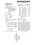
FIG. 1 is a schematic block diagram of a computer system
incorporating the present invention;
FIGS. 2. 3. 4 and 5 are more detailed schematic logic
after a period of keyboard inactivity saved power as well as
prolonged the life of the display and was widely utilized. A
hard disk unit was developed which reduced the power used
diagrams of portions of the computer system of FIG. 1;
by the controlling electronics by utilizing only certain por~
sequences for preparing the computer system of FIG. 1 for
FIGS. 6A. 6B and 6C are ?owchart illustrations of
utilizing the present invention; and
tions of the track for servo information and turning oil‘ the
FIGS. 7A. 7B and 7C are ?owchart illustrations of a
read channel circuitry until just before a servo burst was 65
expected. Additionally. a programmable value could be
sequence for controlling portions of the computer system of
provided to the hard disk unit so that after a given inactivity
FIG. 1 according to the present invention.
Re. 36.189
3
4
DETAILED DESCRIPTION OF THE
PREFERRED EMBODIMENT
36 or the keyboard interface 40 or appropriate accesses to
the ?oppy disk controller 32. The power control logic
circuitry 42 monitors the state of a line called ACPWR.
Referring now to FIG. 1. the letter C generally represents
a computer system incorporating the present invention. An
address and data bus 20 is the primary communication
pathway in the computer system C. Attached to this address
which line indicates whether the power which is being
consumed by the computer system C is being supplied by an
alternating current source or whether the computer system C
is operating off of its internal batteries 54. The power control
logic circuitry 42 monitors a line referred to as the SWNO*
line. which is pulled up to a high level by a resistor 56 and
which is connected to ground by a standby switch 58. The
and data bus 20 are numerous units. including a central
processing unit or microprocessor 22. memory devices 24. a
CMOS memory and clock 26. a direct memory access
10
(DMA) controller 28. a serial interface 29. a modem 30. a
presence of an asterisk after a signal or line indicates that the
?oppy disk controller 32. a hard disk controller 34. a parallel
signal or line is an active or true low signal or line. rather
printer interface 36. a display controller and adaptor 38. a
than the conventional active or true high state. The standby
keyboard interface 40. and power control logic circuitry 42.
switch 58 is a normally open switch which is momentarily
closed by the user and is used to place the computer system
C in standby mode or wake the computer system C up from
The microprocessor or CPU 22 is preferably a CMOS
version of the Intel Corporation 80286 microprocessor. The
CMOS version of the processor is preferable because of its
standby mode. Additionally. the power control logic cir~
lower power consumption while operating and because it is
cuitry 42 monitors the status of two signals referred to as
a fully static device which is capable of operating with a zero
LOWBATI and LOWBAT2. which are developed by the
frequency clock and yet not losing any data. The memory
devices 24 are composed of read-only memories (ROM’s)
battery voltage logic 60 which monitors the charge remain
and random access memories (RAM’s). The RAM’s in the
level indicating that approximately only 10% of a full charge
ing in the batteries 54. If the charge is below a ?rst given
preferred embodiment are preferably pseudostatic devices
remains. this is the LOWBATl level and the LOW'BAT 1
which contain their own individual refresh circuitry so that
- signal is set to re?ect this state. If the batteries continue to
other portions of the computer C need not be activated to
25
provide refresh signals to the memories during low power
consumption modes. The CMOS memory 26 is preferably
powered by its own separate battery 44 so that certain
be discharged. they eventually reach a second lower energy
level. which is referred to as the LOWBAT2 level and the
LOWBAT2 signal is set accordingly. The LOWBAT2 level
is reached when approximately only 5% of a full charge
remains in the batteries 54. These level signals are provided
critical or useful system con?guration information can be
retained at all times and not be stored on disk units or
to indicate to the user warning levels relating to the amount
prompted for each time the computer system C is turned on.
The serial interface 29 is preferably an asynchronous inter
face and includes the customary universal asynchronous
receiver transmitter (UART) devices and appropriate buff
ering and level shifting circuitry. The modem 30 also
contains the appropriate UAKT to perform the parallel/serial
of time available before depletion of the battery and to
indicate to the computer system C the advisability of oper
35
conversions necessary and contains the necessary tone
developing and receiving circuitry and telephone line inter
face circuitry to allow the modem 30 to communicate over
conventional telephone lines.
The ?oppy disk controller 32 interfaces to a ?oppy disk46
drive. The hard disk controller 34 is coupled to a hard disk
unit 48. The hard disk unit 48 in the preferred embodiment
is of a design as indicated in the prior art section as being
appropriate for low power consumption applications. The
display controller and adaptor 38 is coupled to a liquid
crystal display (LCD) 50. The LCD 50 in the preferred
embodiment includes a backlight. The display controller and
adaptor 38 includes the capability to bank the LCD 50 after
a period of time has elapsed without a keystroke entry. to
off when the battery is su?iciently charged. begins ?ashing
45
50
preserve the life of the LCD 50 and to reduce power
consumption. In the preferred embodiment the display con
troller and adaptor 38 is designed to be compatible with a
standard referred to as the VGA standard. The display
controller and adaptor 38 is designed to be optionally
SS
connected to an external high quality color monitor and
therefore includes the necessary circuitry. such as a RAM
DAC or color palette device. to allow the utilization of the
monitor. The keyboard interface 40 connects the CPU 22 to
a keyboard 52. which includes a dedicated microprocessor
for key scanning functions and communication with the
keyboard interface 40 and has a line to receive a power down
signal from the power control logic circuitry 42.
A power control logic circuitry 42 performs the functions
of monitoring the address and data bus 20 and determining
the intervals since the last access to the serial port 29. the
modem 30. the hard disk controller 34. the printer interface
ating at full power levels.
The power control logic circuitry 42 has a number of
outputs. Two outputs are used to drive the power liglt
emitting diode (LED) 62 and the battery state LED 64. The
power control logic circuitry 42 drives the power LED 62 in
a continuous fashion if the computer system C is turned on
and not in standby mode. If the computer system C is in
standby mode. indicating that it is in its low power con
sumption mode and is halted. the power LED 62‘is ?ashed
to provide an indication to the user. The battery LED 64 is
at a ?rst relatively slow rate of 1 Hz when the LOWBATl
condition exists and ?ashes at a higher rate. for example a
2 Hz rate. when the LOWBAT2 condition exists. These
various battery level warnings are visual indicators to the
user as to the remaining energy in the batteries. The power
control logic circuitry 42 has a series of outputs which are
connected to several ?eld elfect transistors (FET’s) 66. 68
and 70. which are used. respectively. to control power to the
modem 30. the hard disk 48. and the LCD 50.
The power control logic circuitry has an output referred to
as the SLEEP* signal which is provided to an inverter 72 to
produce the SLEEP signal. The presence of an active or true
SLEEP signal indicates that the computer system C is in
sleep or standby mode. The SLEEP signal is connected to
the keyboard 52 to cause the keyboard electronics and
microprocessor to go into a low power condition.
Additionally. the SLEEP signal is provided to an FET 74 to
remove power from various miscellaneous circuitry 76 in
the computer system C. It is to be noted that power is not
removed from many portions of the computer system C.
65
such as the CPU 22 and the memories 24. The SLEEP signal
is provided to the memory devices 24 to cause the RAM’s
to enter their pseudostatic mode and begin controlling their
own refresh.
Re. 36.189
5
6
The SLEEP signal also is inverted and provided to the
input of a two input clock AND gate 78 used to disable the
system clock. A crystal 80 is connected to a clock generator
circuit 82 which produces a CLK signal which is provided
to the power control logic circuitry 42 for its internal
clocking functions and which is provided to the second input
of the clock AND gate 78. The output of the clock AND gate
78 is the system clock which is used by the CPU 22 and
the standby switch 58. a one CLK signal length pulse is
developed at the output of the NAND gate 106 when the
standby switch 58 is released and is applied to the reset input
of the sleep ?ip-?op 110. This pulse resets the noninverting
output of the sleep ?ip-?op 110. The noninverting output of
the sleep ?ip-?op 110 is connected to one input of a two
input NAND gate 118. The other input of NAND gate 118
is connected to the inverted output of the LCD ?ip-?op 160.
This dual connection of the sleep ?ip-?op output 110 and the
LCD ?ip-?op 116 output is used in the preferred embodi
ment because of constraints relating to the powering
sequence of the LCD 50. Therefore when the output of the
other portions of the computer system C for clocking
functions. Thus when the SLEEP signal is at a high state. the
output of the AND gate 78 is at a low state. thereby stopping
the system clock and causing the clocked CMOS circuitry
located in the computer system C to go into a very low
power state. Alternatively. if it is desired that the system
clock be stopped at a high level. the clock AND gate 78 can
be replaced by an OR gate and the SLEEP signal directly
applied. For details regarding stopping the clock signal to
15
sleep ?ip-?op 110 goes low. the output of NAND gate 118
goes high and therefore the signal present at the D input of
a D-type ?ip-?op 120 goes high. This ?ip-?op 120 is
clocked by the inverted CLK signal is produced by an
inverter 122. When the next falling edge of the CLK signal
the CPU 22. refer to Harris Corporation ADC 286 Hardware
is encountered. the SLEEP* signal. which is the non
Reference Manual. p. A-6. the contents of which are incor
inverted output of ?ip-?op 120. goes high indicating that the
computer system C is no longer in standby mode. The
porated by reference herein.
The CLK signal developed by the clock generator circuit
82 is tied to the clocking input of a D-type ?ip-?op 100
(FIG. 2). The D input to the ?ip-flop 100 is provided by the
output of a two input NOR gate 102. The inputs to the NOR
gate 102 are the SLEEP* signal developed by the power
control logic circuitry 42 and the SWNO* signal provided to
the power control logic circuitry 42. The NOR gate 102 is
used to indicate and receive the depressing of the standby
switch 58 when the system is in standby mode to begin the
SLEEP* signal feeds back to NOR gate 102 to clear the
pulse provided by NAND gate 106.
The inverting output of ?ip-?op 120 is connected to the D
input of a D-type ?ip-?op 124. The clocking input to
?ip-?op 124 is provided by the CLK signal. so at the next
25
rising edge of the CLK signal the noninverting output of
?ip-?op 124 goes low. This output of the ?ip-?op 124 is tied
to one input of a two input OR gate 126. with the other input
indicating that the computer system C is in standby mode
of the OR gate 126 being the CLK signal. Thus. when the
noninverting output of ?ip-?op 12A is low. the output of the
OR gate 126 proceeds to follow the CLK signal and is
and the user desires to wake up the computer system C. the
referred to as the BCLK signal. This is the blocked clock or
wake up procedure. When both signals are in a low state
stopped cock signal for use with the power control logic
low signal present at the D input is clocked to the Q or
noninverting output of the ?ip-?op 100 on the next rising
edge of the CLK signal. The noninverted output of ?ip-?op
100 is provided to the D input of a D-type ?ip-?op 104. The
clocking signal of the second D-type ?ip-?op 104 is also the
CLK signal. The inverted output of ?ip-?op 100 and the
35
non-inverted output of ?ip-?op 104 are inputs to a two input
NAND gate 106. The output of the two input NAND gate
106. whose active condition is a low pulse one CLK signal
cycle in length after the standby switch 58 is released. is
provided to one input of an AND gate 108. whose output is
applied to the reset input of a sleep D-type ?ip-?op 110.
circuitry 42 so that when the computer system C is in
standby mode even the portions of the power control cir'
cuitry 42 which can be stopped are stopped
When the computer system C is to enter standby mode.
the inverting output of the LCD ?ip-?op 116 is in a high
state because in the preferred embodiment it is desired that
the LCD power he turned off prior to removing the clock
from the various portions of the computer system C. The
noninverting output of the sleep ?ip-?op 110 is set high on
a following access of the CPU 22 to the power control
register 109. so that both inputs of the two input NAND gate
118 are high so that a low signal is presented to the input of
The sleep ?ip-?op 110 is one bit in a register referred to
as the power control register 109. The power control register 45 ?ip-?op 120. At the next falling edge of the CLK signal the
SLEEP* signal goes low. indicating that the computer
109 contains the storage elements which control and indicate
which of the peripheral devices and the system are powered
on. The power control register 109 is readable by the
computer system C and writeable by the computer system C.
The various additional storage elements comprising the
power control register 109 are a modem D-type ?ip-?op 112.
a RAMDAC d-type flop-?op 113. a hard disk D-type ?ip
?op 114. and an LCD D-type ?ip-?op 116. All of the
?ip-?ops in the power control register 109 have their D
inputs coupled to the appropriate lines of the data bus 20
through buffers (not shown) and have their clocking inputs
tried to a signal referred to as PWRCTLWR‘“. The
PWRCI‘LWR* signal is a signal which indicates that a write
operation has been directed to the power control register 109
and is of a phase such that the rising edge of the signal is
available when the data is valid at the inputs to the various
?ip-?ops. The non-inverted outputs of the power control
register ?ip-?ops are combined to form the PWRCTL data
lines and are connected to the system address and data bus
20 via appropriate buffering devices (not shown).
When the computer system C is in standby mode. which
may be referred to as being asleep. and the operator presses
system C is in the standby mode and the inverting output of
?ip-?op 120 goes high. which output is then clocked through
?ip-?op 124 to stop operation of the clock to the other
50
55
portions of the power control logic circuitry 42 by means of
OR gate 126.
The non-inverted output of the RAMDAC ?ip-?op 113 is
supplied to one input of an OR gate 128. The second input
to OR gate 128 is the ACPWR signal. which indicates that
AC power is applied. The output of the OR gate 128 is a
RAMDACON signal to indicate the power should be turned
on to the RAMDAC located in the display control adaptor
38. As discussed. the RAMDAC is useful only with an
external monitor in the preferred embodiment because the
LCD display is not color and therefore there is no need to
perform the necessary color pallette lookup performed by
the RAMDAC. Therefore if the RAMDAC bit is set on or
the computer system C is being powered by the external AC
supply. the RAMDAC is turned on. Otherwise the RAM
65 DAC is turned off to conserve power.
The non-inverted output of the modem ?ip-?op 112 is
supplied to the D input of a D-type ?ip-?op 130. The
Re. 36.189
7
8
clocking signal to this ?ip-?op is a signal referred to as
is the MODEMON signal and is supplied to the D input of
3F0-3F7. which the complete range for access to the ?oppy
disk controller 32 in the preferred embodiment. However.
because of certain features in other control sequences which
are present in the computer system C that had to be retained
a second D-type ?ip-?op 132 and to one input of a two input
for compatibility reasons. one address in the range cannot be
CLKl3uS which provides an approximate 13 microsecond
clocldng signal to ?ip-?op 130. The output of ?ip-?op 130
EQUAL gate 134. The MODEMON signal is supplied to an
utilized for inactivity montoring because this address is
FBI‘ 66 to control the power to modem 30. The second
accessed on a relatively frequent basis to prevent other
?ip-?op 132 is also clocked by the CLK13uS signal and has
potential systems problems from occurring and does not
necessarily indicate system activity. Therefore the FLOPPY
its non-inverting output connected to the second input of the
EQUAL gate 134. The output of the EQUAL gate 134 is
supplied to one input of a two input NAND gate 136. The
output of NAND gate 136 is referred to as the MODEMRST
signal. the modem reset signal. The second input of the
NAND gate 136 is connected to the RESET* signal. which
is the main reset signal present in the computer system C.
Assuming that the RESE'I‘* signal is high. the MODEMRST
signal is pulsed high for one 13 microsecond CLK signal
cycle when the modem ?ip-?op 112 output changes. Thus.
signal must be combined with other bits of the address to
determine that the speci?c undesired address is not being
presented. The FLOPPY signal is ?rst combined with the
zero or least signi?cant address signal by NOR gate 160 so
that any access to an odd address produces a high level
15
there is a rest pulse after the modem 30 is turned on to allow
the modem 30 to properly initialize itself.
signal which is applied to one input of the OR gate 152. The
ADD<2> signal representing the second east signi?cant bit
of the address is supplied to the an input of a NOR gate 158
along with the FLOPPY signal. so that all addresses having
The non-inverting output of the hard disk ?ip-?op 114 is
a least signi?cant hexadecimal digit in the range 4—7 are
selected. The output from NOR gate 158 is supplied to one
input of a two input OR gate 162. whose output is connected
the HDISKON signal and is connected to an FET 68 to
control the power to the hard disk unit 48.
to the fourth input of the four input OR gate 152. The second
input to the OR gate 162 is provided from a third NOR gate
156 whose inputs are the ADD<1> signal or next least
The non-inverting output of the sleep ?ip-?op 110 and the
inverting output of the LCD ?ip-?op 116 are provided to the
two inputs of a NOR gate 138. The output of the NOR gate
25
138 is the LCDON signal which is connected to an FBI‘ 70
to control the supply of power to the LCD 50. The coupling
of the SLEEP and LCD ?ip-?op output signals is to prevent
the LCD power from being removed in improper sequence
30
and possibly damaging the LCD 50.
The computer system C includes a parallel printer inter
face 36. In the preferred embodiment. this parallel printer
interface 36 can be addressed at any one of three selectable
addresses which are generally referred to as LP'Tl. LP'I‘Z 35
and LP'I‘3. The selection of which of the three printer
locations is de?ned by the state of two bits in a peripheral
control register. the two signals corresponding to the two bits
provided to the gating inputs of a 4:1 multiplexer 150. which
45
to as LP'[‘2*. which is indicative of an access to port address
37A-37F. is connected to the second input of the multiplexer
150. A signal referred to as LP'T3*. which goes low when an
access is made to the address 278-27F. is connected to the
third input to the multiplexer 150. The fourth input to the
multiplexer 150 is tied to a positive level. The output of the
multiplexer 150 is a signal referred to as PTR. and goes high
address accessed by the above-given problem.
The output of the four input OR gate 152 indicates that a
proper address of the monitored devices has been presented
on the address bus 20. This signal is provided to one input
of each of two different two input NAND gates 164 and 166.
The second input of the NAND gate 164 is a signal referred
to as I/ORD. which indicates that a valid I/O address space
referred to as PCR<6> and PCR<5>. These two signals are
has an inverted output (FIG. 4). A signal referred to as the
LPl‘l* signal is applied to the zero channel input of the
multiplexer 150 and is true when an access is being made to
the address of the LPTl printer which. in the preferred
embodiment. has an address of 3BC-3BF. A signal referred
signi?cant bit of the address and the FLOPPY signal. so that
the output of the NOR gate 156 goes high only when an
address having a least signi?cant hexadecimal digit of 0. 1.
4 or 5 is present. Thus. the NOR gates 156. 158 and 160
produce a high level signal for addresses in the range of
3F0-3F7. except when the address is 3P2. which is the
50
or port read operation is in progress. The second input to the
other NAND gate 166 is a signal referred to as the I/OWR
signal. which indicates that a valid I/O address space write
opuation is in progress. The use of these two signals is
necessary in combination with the addressing information to
determine that the monitored devices are actually being
accessed The outputs of the NAND gates 164 and 166 are
supplied to two inputs of an AND gate 168 whose output is
the DEVACT* signal. which is low when a monitored
device is being accessed. The DEVACT* signal is low only
the length of the I/ORD or I/OWR signals in the preferred
embodiment because the 110 control signals are present for
shorter periods than the address information.
The DEVACT* signal is applied to one input of a two
to indicate that an access is being made to the selected
input NAND gate 200 (FIG. 3). The second input to the
NAND gate 200 is a signal designated ACTMONWR*.
printer location. The HR signal 150 is connected to one
which indicates that a write operation is occurring to the
input of a four input OR gate 152. Another of the inputs to
this four input OR gate 152 is the output of yet another four
input OR gate 154. The four inputs to four input OR gate 154
are the HDISK signal. the MODEM signal. the UART
signal. and the KEYBD signal. These signals represent.
respectively. accesses to the addresses of 1F0-1F7.
2F8-2FF. 3P‘8-3FF. and 060 and 064. When any one of these
signals is present. this indicates that the CPU 22 or other
device controlling the bus may be accessing one of these
speci?ed addresses.
A signal designated FLOPPY is supplied to one input of
a series of three NOR gates 156. 158 and 160. The FLOPPY
signal indicates an access request in the address range
activity monitor interval register. The ACI‘MONWR’“ signal
is also supplied to the enabling input of a latch 202. The data
input signals to the latch 202 are provided by connection to
the data bus 20. so that the latch 202 is a ?rst register or
buffer contained in the activity monitor time T.
The output of the NAND gate 200 is connected to the
clock input of a D-type ?ip-?op 204. The D input is
connected to a high level signal so that whenever the
DEVACI‘* signal is deactivated to a high state indicating
that an access to a monitored device has just completed. the
?ip-?op 204 is clocked. The noninverted output of the
?ip-?op 204 is connected to the D input of a second D-type
?ip-?op 206. The clocking input of the ?ip-?op 206 is
Re. 36.189
9
10
supplied by the BCLK signal. The inverting output of the
CPU 22 can determine the actual countdown time remaining
prior to entering a sleep or standby status.
The ACT'IVE* signal is connected to the second input of
NAND gate 214 and when the ACT'IVE* signal goes low.
this causes the output of NAND gate 214 to go high. so that
on the second BCLK signal rising edge after a monitored
device has been accessed. the countdown timer 220 is
reloaded and the process is reinitiated and the ACI'IVE*
signal returns to a high state. This pulse width of the
ACT'IVE* signal is sufficient for the level 15 interrupt to be
generated as needed to start execution of the interrupt
routine which determines if and when it is appropriate to go
into standby mode. The two latches 202 and 210 and the two
?ip-?ops 206 and 216 are reset by a low level of the
?ip-?op 206 is connected to one input of a two input AND
gate 208. whose output is connected to the inverted chip
enable input of a second latch 210. This use of two latches
202 and 210 allows the activity monitor time T to be double
buffered. Additionally. the register 210 includes an output
which indicates that the value latched in the latch 210 is not
zero. The clocking input signal to the second latch 210 is the
BCLK signal.
The output of AND gate 208 is also connected to one
input of a two input OR gate 212. whose other input is the
BCLK signal. The output of OR gate 212 is fed back to the
reset input of ?ip-?op 204 so that each time the DEVACP‘
signal is propagated through the two ?ip—?ops 204 and 206.
the ?rst ?ip-?op 204 is cleared.
The inverting output of the second ?ip-?op 206 is also
15
connected to one input of a two input NAND gate 214. The
output of the NAND gate 214 is connected to the D input of
a D-type ?ip-?op 216 whose clocking input is supplied by
the BCLK signal. The inverting output of the ?ip-?op 216 is
20
connected to one input of an AND gate 218 and the output
of the AND gate 218 is connected to the inverted load input
of the countdown timer 220. which forms the loadable
portion of the timing elements of the activity monitor timer
RESE'I‘* signal.
Thus. the combination of ?ip-?ops 204. 206 and 216 and
various logic gates 200. 208. 212. 214 and 218 reset and
retrigger the countdown timer 220 each time a monitored
device is activated. For example. a clocking signal appears
at ?ip-?op 204. which then provides a high signal to the D
input of ?ip-?op 206. whose inverting output in turn goes
low at the next rising edge of the BCLK signal. This low
output on the inverting output of ?ip-?op 206 enables the
second latch 210 to be reloaded on the next rising edge of the
BCLK signal and the output of ?ip-?op 216 to go low on
that same BCLK signal edge. On the next BCLK signal
T. The timer 220 has an output which indicates when the 25
timer 200 has reached a zero value. The output of the AND
gate 218 is also connected to one input of a four input
rising edge after that. the countdown timer 220 is reloaded
NAND gate 222 whose output is designated the ACI'IVE*
signal and indicates that a device has been active and the
activity monitor timer T has not counted to zero. The
and thus the countdown process recommences.
30
NOTZERO signal provided by the latch 210 is connected to
one input of the NAND gate 222 and the ZERO signal
output from the timer counter 220 is provided to yet another
input of the NAND gate 222. The fourth and ?nal input of
the NAND gate 222 is a signal described as IRQISCLR.
which indicates that the interrupt request 15 has been
cleared. The inputs to the NAND gate 222 are true only
when the activity monitor time T is enabled by the value of
interrupt request register and is provided to the processor by
35
means of the lRQDATA<7-0> lines and appropriate buli
40
supplied to the D input of a ?ip-?op 254. which ?ip-?op 254
is also clocked by the BCLK signal. The inverting output of
the ?rst ?ip-?op 252 is connected to the second input of the
NAND gate 250 and to the ?rst input of a NOR gate 256. By
this connection. the D input to the ?ip-?op 252 remains high
after the initial pulse is received on the ACTIVE"c signal so
that the state of the activity status of the computer system C
ering. The non-inverting output of ?ip-?op E2 is also
the latch 210 not being zero. a device is not active as
indicated by the output of AND gate 218. the countdown
The ACTIVE* signal is applied to one input of a two input
NAND gate 250 (FIG. 5). The output of this NAND gate 250
is connected to the D input of a D-type ?ip-?op 252. This
?ip-?op 252 is clocked by the BCLK signal. The non
inverting output of ?ip-?op 252 is the active status bit of the
timer 220 is at zero count and the level 15 interrupt has been
cleared. This is a general condition that the computer system
C has been inactive for a su?icient period of time as
indicated by the value from which the activity monitor timer
can be determined at any time. The output of the second
T counted down.
45 ?ip-?op 254 is provided to the second input of the NOR gate
256. whose output is connected to one input of a six input
The IRQISCLR signal and the NOTZERO signal are
provided as two inputs to a three input AND gate 224. The
NOR gate 258. The output of the two input NOR gate 256
third input to AND gate 224 is a signal referred to as SSEC
is a pulse having a length of one BCLK signal cycle. In this
which is a pulse having a width of one BCLK signal cycle
manner only a short pulse is formed and provided to the
and occurs every ?ve seconds. This pulse is produced by a 50 NOR gate 258 when the inactivity timeout is reached to
ripple counter 226 which has the BCLK signal as one input
cause the IRQlSREQ signal to be developed.
to produce the necessary pulse width. a second signal input
As can be seen by the fact that there are six inputs to the
of the CLKl3us signal to produce an initial clock cycle
NOR gate 258. there are a plurality of di?erent ways in
which is divided down to a ?ve second cycle and a reset
which the IRQISREQ signal can be generated. ‘These addi
signal provided by the output of the AND gate 218. The 55 tional ways are provided in the preferred embodiment to
output of the AND gate 224 is provided to the enable input
allow the computer system C to know the states of various
of the countdown timer 220 and is synchronized to the
events and switches relating to power usage and to warn the
BCLK signal the clocking input to the countdown time 220.
user at appropriate intervals. For example. the ACPWR*
so that the countdown timer 220 is advanced or decremented
only one count per ?ve second interval. The data outputs of
the ?rst latch 202 are connected in parallel to the data inputs
to the second latch 210. whose data outputs in turn are
connected to the inverting data inputs of the countdown
timer 220. The inverted data outputs of the timer 220 are
signal is provided to the D input D-type ?ip-?op 260. whose
clocking signal is the BCLK signal. The non-inverting
output of the ?ip-?op 260 is connected to the D input of a
D-type ?ip-?op 262 and to one input of a two input XOR
provided to the data bus 20 over a line or series of lines 65
referred as to as the ACI‘MN data lines to provide the
gate 264. The second input to the XOR gate 264 is provided
by the noninverting output of the second ?ip?op 262. which
?ip-?op is clocked by the BCLK signal. The output of the
XOR gate 264 is thus a one BCLK signal cycle length pulse
activity monitor timer value to the CPU 22. In this way the
which occur whenever the condition of me AC power
Re. 36.189
11
12
changes and is provided to the NOR gate 258 to generate the
lRQlSREQ signal. The state of the ACPWR* signal is
stored and transmitted to the lRQDATA lines by the invert
ing output of the ?ip-?op 260. Thus. the NOR gate 258 is
utilized to allow the computer system C to note any change
in the AC power status such as. for example. when the AC
adaptor is provided or removed. This allows the computer
system C to note when it is entering battery-powered opera
and latched in until the IRQlS ?ip-?op 278 is reset. The
non-inverting output of the IRQIS ?ip-?op 278 is the
IRQISREQ signal which is supplied to the interrupt con
troller which is interfaced to the CPU 22 and handles the
processing of the interrupt request.
There are two remaining ?ip-?ops utilized in the power
conservation circuitry relating to the interrupt circuitry and
these are the IRQISEN D-type ?ip-?op 280 and the
tion and thus the power conservation mode may be appro
priate. This operation is seen in more detail in the ?owchart
IRQISCLR D-type ?ip-?op 282. The lRQlSEN ?ip-?op has
its D input coming from the data bus 20 and is clocked by
a signal referred to as the IRQl5WR* signal. which indi
cates that a wire operation is occurring to the IRQlS register.
The IRQlS register location provides the states of the
illustrations of the operating sequences of the computer
system C.
Similar ?ip-?op circuits are present for utilizing the
LOWBATl and LOWBAT2 signals. Thus two inputs to the
NOR gale 258 indicate whenever the computer system C has
changed the battery charge status to or from LOWBATl to
LOWBA'I‘Z. The actual LOWBAT signals are latched by a
?rst D-type ?ip-?op 290 and 292 in the series and the
noninverted outputs are presented to the lRQDATA lines. A
second D-type ?ip-?op 294 and 296 is closed by the BCLK
signal and has the D input connected to the preceding
signals forming the IRQDATA lines during a read operation
and allows data to be written to the IRQISEN and
IRQlSCLR ?ip-?ops 280 and 282 during Write operations.
The data present on the data bus is latched at this time and
20
?ip-?op 290 and 292 noninverting output. The noninverting
outputs of the ?ip-?ops 290 and 292 and 294 and 296 are the
inputs to an XOR gate 297 and 298. whose output is
connected to NOR gate 258 to produce the necessary signal
to trigger a level 15 interrupt.
The SSEC signal is combined with the latched LOW
BAT2 and LOWBATI signals by AND gate 266 whose
output is connected to NOR gate 258. so that whenever the
computer system C is in a LOWBAT2 condition. every ?ve
the IRQISCLR ?ip-?op 282 is the IRQISCLR signal. goes
to a high state and is fed back to the IRQDATA lines for
25
30
remaining input to this AND gate 284 is the RESET* signal
which is also provided to the reset inputs of the IRQISEN
and IRQISCLR ?ip-?ops 280 and 282 and to the ?ip-?ops
in the LOWBATI. LOWBAT2 and ACPWR portions of the
circuitry. The output of the AND gate 284 is a clear signal
used to clear the IRQlS ?ip-?op 278 and to clear the active
?ip-?ops 252 and 254 and the standby switch ?ip-?ops 268.
35
270 and 274.
This completes the detailed description of the circuitry
utilized in the computer system C according to the present
invention to provide the power conservation features of the
present invention. This circuitry is used in conjunction with
that the computer system C is to go to an inactive status or
standby. based on the user demand. The SLEEP‘ signal is
provided to the D input of a D-type ?ip-?op 268 with the
SWNO* signal provided to the clocking input. In that way.
if the SLEEP* signal is high indicating that the computer
system C is active. when the standby switch 58 is depressed.
a high state is produced at the noninverting output trans
mitted to the noninverting output of the ?ip-?op 268. which
is connected to the D input of a next D-type ?ip-?op 270.
The clocking signal to the second ?ip-?op 270 is provided
evaluation by the CPU 22. The inverting output of the
lRQlSCLR ?ip-?op 282 is the IRQ15CLR* signal and is
provided as one input to a two input AND gate 284. The
seconds a level 15 interrupt is received to allow the user to
be reminded that he is in LOWBAT2 condition and that there
is very little energy remaining in the batteries 54.
The ?nal input to NOR gate 258 is based on the SLEEP‘
signal and the SWNO* signal. The combination of the
signals is used to indicate that the user has pressed the
standby switch 58 while the computer system C is active and
the output of the lRQlSEN ?ip-?op 280 is provided to the
IRQDATA lines and is the IRQISEN signal.
Also clocked in by the IRQ15W'R* signal is another bit of
the data bus 20. which is the lRQlSCLR signal. When a high
state of this signal is clocked in. the non-inverting output of
certain operating sequences provided in the read-only
memory space of the computer system C to perform the
power conservation functions of the present invention.
When the power to the computer system C is initially
45
turned on. the power on sequence 300 (FIG. 6A) is com
menced. The first step of the power on sequence 300 is step
302. where a determination is made by reading the IRQ
270 is provided to the IRQDAI‘A lines and is considered to
DATA lines as to whether the computer system C is in a
LOWBAT2 condition. If the computer system C is in a
be the standby switch signal which is interpreted by the CPU
LOWBAT 2 condition. control proceeds to step 304 where
22. The inverted output of ?ip-?op 270 is provided to one
input of a NOR gate 272. The non-inverting output is also
supplied to the D input of a third D-type ?ip-?op 274. which
proceeds to step 305 where the computer system C is halted.
by die BCLK signm. The noninverting output of ?ip-?op
12 beeps are issued to warn the user of this state and control
is clocked by the BCLK signal. The non-inverting output of
?ip-?op 274 is connected to the second input of the NOR
gate 272. so that in a manner similar to the circuitry relating
to the ACI‘IVE* signal. only a short pulse one BCLK signal
cycle in length is presented to the NOR gate 258 to indicate
the user‘s desire to place the computer system C in standby
mode.
55
Thus. when the computer system C is in a LOWBAT2
condition. it cannot be used until it is removed from this
condition. This is done because it is presumed that there is
insu?icient energy in the batteries 54 to allow any signi?cant
activity of the computer system C and so the possibility of
losing data is now allowed.
If the computer system C is not in a LOWBAT2 condition.
control transfers from step 302 to step 306 where other
The output of the NOR gate 258 is connected to one input
of a NAND gate 276. whose output is connected to the D
activity relating to powering up the system is performed.
input of the IRQIS D-type ?ip-?op 278. The IRQIS ?ip-?op
step 308 where a determination is made as to whether the
values contained in the CMOS RAM 26 are valid. The
65 CMOS RAM 26 is used to contain certain values relating to
278 is clocked by the BCLK signal and has the inverting
input coupled back to the second input of the NAND gate
276. In this way. whenever a pulse is received by the NOR
gate 258. the signal is detected by the IRQlS ?ip-?op 278
After completing this necessary activity. control proceeds to
the con?guration of the system C which allows the computer
system C not to ask the user this information or have the
Re. 36.189
13
14
information stored in a ?le contained on a disk. If the CMOS
Control proceeds from step 330 to step 328. where other
information is valid. control proceeds to step 310 where the
computer system C determines whether power conservation
necessary power up and self-test activities are preformed.
Control then proceeds from step 328 to step 331 where the
should be activated. There are two bits contained in a
computer system C makes a second determination as to
whether a LOWBAT2 state exists. If so. control proceeds to
register in the computer system C which are used to indicate
the desired initial state of the power conservation system.
step 332 where the user is again prompted with 12 beeps as
The three states that are available are the power conservation
an audible indication that the LOWBAT 2 condition exists.
On State. the power conservation Oil‘ State. and a power
conservation Auto State. In the power conservation On
Control then proceeds to step 334 which is the beginning of
the boot sequence in which the operating system is loaded in
from the storage media.
If the computer system C is not in a LOWBAT2 condition.
control proceeds from step 331 to step 336 where a test is
State. the power conservation techniques of the present
invention are utilized at all times. In the power conservation
01f State. the power conservation techniques are not uti
lized. The preferred initial state is the power conservation
Auto State. which is utilized so that the computer system C
made to see if the computer system C is in a LOW'BATI
condition. If so. control proceeds to step 338 where 6 beeps
and determine which operating system will be controlling
the operations of the machine after booting operations are
completed. Thus. power conservation in the Auto State is
enabled when certain operating systems are employed and is
not operational when certain other operating systems are
employed. This allows the greatest ?exibility of operation.
are issued. thus allowing the user to distinguish between the
LOWBA'I‘I and LOWBATZ conditions audibly. Control
then proceeds from step 338 to step 334. which is also where
control would proceed from step 336 if the computer system
C was not in a LOW'BATl condition. The computer then
20
If the computer system C determines in step 310 that the
power conservation is selected to be on. control proceeds to
step 312 where the power conservation mode is enabled and
the system inactivity timer or activity monitor timer T is set
with a value obtained from the CMOS 26. Control then 25
proceeds to step 314.
If it was determined in step 310 that the power conser
vation mode was not to be enabled on at all times. control
proceeds to step 316 where a determination is made as to
whether power conservation features are to be turned oil. If
so. control proceeds to step 318 where the power conserva
30
35
counter for a suf?cient interval. generally 70-85 seconds. so
enabled. control proceeds to step 344. where control is
returned to the interrupted sequence. If IRQ15 is not enabled
in step 342. control proceeds to step 346 where a determi
nation is made if the desired power conservation mode is o?.
If so. control proceeds to step 344 and returns. If the power
that the remaining portions of the power up routine and
operating system are executed and locked. and an interrupt
is developed after that period of time. This allows su?icient
time for the operating system to be installed in the computer
conservation mode is not off. control proceeds from step 346
to step 348 where a determination is made to see if it is time
to enable power conservation. If not. control proceeds to
state 344. If it is time. control proceeds to step 350 where
IRQ15 is enabled. and the IRQISDATA lines or status value
is saved for later use. Control then proceeds to step 344. and
system C and begin controlling operation of the computer
system C. If the operating system does not allow access to
the ROM memory portion where the auto delay interrupt
operation proceeds in the interrupted sequence.
45
interrupt will not be obtained. and power conservation will
not be enabled. Also in step 320. the IRQ15 is cleared and
Whenever the inactivity timer has timed out such that it is
appropriate to enter standby mode or when one of the
various parameters related to power conservation such as the
power source. the battery condition. or a user request for
disabled by writing the proper values to the IRQ15 register.
Finally in step 320. the system inactivity timer T is set to the
default value.
Control then proceeds from step 320 to step 314 where the
computer system C determines if the computer system is
being powered by the batteries 54. If so. control proceeds to
standby status is developed. a level 15 interrupt or IRQ15 is
requested. and an IRQ15 interrupt sequence 400 is per
formed. The preferred embodiment uses IRQ15 for this
purpose because it is generally not a defined interrupt and
thus is relatively available with a minimum number of
step 322 where a second check is made to see if the CMOS
26 is valid. If so. control proceeds to step 324 (FIG. 6B)
where the system inactivity timer T is set with the value
computer system C containing the proper routine. then
control proceeds to the auto delay interrupt sequence 340
(FIG. 6C). Control starts in sequence 340 by having the
computer system determine whether IRQ15 has been
enabled in step 342. If IRQ15 is enabled. this indicates that
interrupts and thus be recognized for action. If IRQ15 is
State was not selected in step 316. or if the CMOS was
routine is located. then a proper entry to that selected
If the selected power conservation mode was automatic.
a timer is set in step 320 with the auto delay interrupt time
and eventually an auto delay interrupt occurs. If the oper
ating system in control of the machine at that time is one
which allows access to the read-only memory portions of the
the power conservation mode is already active to cause
tion o? ?ag is set for further use in later operations and then
control proceeds to step 314. If the power conservation OE
determined to be not valid in step 308. control proceeds to
step 320 where the computer system C sets the auto delay
proceeds to boot up and load the operating system.
55
con?icts with application software. The IRQ15 sequence
400 begins at step 402 where the computer system C reads
the IRQ15 status values from the IRQDATA lines and
contained in the CMOS 26. If the CMOS 26 is not valid
retrieves the old IRQ15 status values from a saved location
control proceeds to step 326 where the system inactivity
in memory. Control proceeds from step 402 to step 404
where write operations are performed to the lRQ register so
that the pending IRQ15 is cleared and remains enabled.
timer T is set with a default value. Control proceeds from
step 326 or from step 324 to step 328.
If it was determined in step 314 that the system was not
powered by the battery. that is. was powered by the AC
adaptor or from an external base unit. control proceeds from
step 314 to step 330 where the system inactivity time is set
Control then proceeds to step 406 where a determination is
made as to whether the system was previously AC powered.
If so. control proceeds to step 407 where a determination is
made to determine if the computer system C is switching to
to zero because there is no need to conserve power when 65 battery powered operation. If it is powered by an external
source. control proceeds to step 408 where a determination
powered from the external source and a zero value in the
is made as to whether the old and new IRQ15 status values
latch 210 prevents the ACTIVE* signal from being asserted.